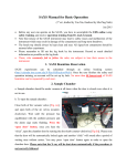
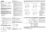
1
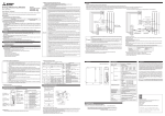
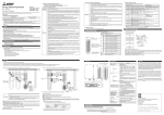
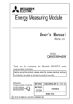
Energy Measuring Unit
Mitsubishi
Programmable Controller
3.2 Matters concerning the preparation before use
・Use the unit in the specified usage environment and conditions.
・The setting of this unit (primary voltage, primary current)is necessary before using it.
※Please refer to "User’s Manual (Details)" about each setting method.
3.3 Installation and Wiring Precautions
・Shut off the external power supply for the unit in all phases before installing or wiring. Failure to do so
Danger
may cause an electric shock or damage of the unit.
Model QE81WH4W
User’s Manual (Hardware)
Before using this unit, please read both this manual and Details carefully and pay full attention to safety to handle this unit
correctly.
・Make sure that the end users read this manual and then keep the manual in a safe place for future reference.
ABOUT MANUALS
The following manuals are also related to this unit.
Order each manual as needed, referring to the following list.
Manual name
Manual number(model code)
Energy Measuring Unit User’s Manual(Details) QE81WH4W
IB63704(19H861)
・
COMPLIANCE WITH THE EMC AND LOW VOLTAGE DIRECTIVES
(1) For programmable controller system
To configure a system meeting the requirements of the EMC and Low Voltage Directives when incorporating the
Mitsubishi programmable controller (EMC and Low Voltage Directives compliant) into other machinery or equipment,
refer to Chapter 9
"EMC AND LOW VOLTAGE DIRECTIVES" of the QCPU User's Manual (Hardware Design, Maintenance and
Inspection).
The CE mark, indicating compliance with the EMC and Low Voltage Directives, is printed on the rating plate of the
programmable controller.
(2) For this unit
For the compliance of this unit with the EMC and Low Voltage Directives, refer to Section 6.1 Wiring.
1. Features
(1)This Energy Measuring Unit can measure various types of electric quantity just ONE unit..
This Energy Measuring Unit can measure electric energy, reactive energy, current, voltage, power, power factor, and
frequency.
Both consumption and regeneration of the electric energy can be measured.
(2)Extensive monitoring functions
In addition to memorizing the maximum and minimum values, two types of alarm monitoring for upper and lower limit
can be performed without a ladder.
(3)It also can measure the electric energy for a certain period.
It can measure the electric energy for the duration of time for which the output device is on.
This feature enables to acquire the electric energy needed during device operation or energy per tact.
2. Checking packaged contents
The following items for this device are included in the package. Check that no items are missing.
・ Energy Measuring Unit x 1
・ User’s Manual (Hardware) x 1
3. Safety Precautions
3.1 Precautions for Operating Environment and Conditions
Do not use this product in the places listed below. Failure to follow the instruction may cause malfunctions and a life
decrease of product.
・Places the Ambient temperature exceeds the range 0 – 55ºC.
・Places the Relative humidity exceeds the range 5 – 95% or places with dewfall.
・Altitude exceeds 2000 m.
・Places exposed to rain or water drop.
・Dust, corrosive gas, saline and oil smoke exist.
・Vibration and impact exceed the specifications.
・Installed excluding the control panel.
Caution
・Any person who is involved in the installation and the wiring of this Sequencer should be fully competent to do the work.
・Use the programmable controller in an environment that meets the general specifications in the User’s Manual for the
CPU module used. Failure to do so may result in electric shock, fire, malfunction, or damage to or deterioration of the
product.
・To mount the unit, while pressing the unit-mounting lever located in the lower part of the unit, fully insert the unit fixing
projection(s) into the hole(s) in the base unit and press the unit until it snaps into place. Incorrect mounting may cause
malfunction, failure or drop of the unit.
When using the Sequencer in an environment of frequent vibrations, fix the unit with a screw.
・Tighten the screw within the specified torque range. Under tightening can cause drop of the screw, short circuit or
malfunction. Over tightening can damage the screw and/or unit, resulting in drop, short circuit, or malfunction.
・Shut off the external power supply for the system in all phases before mounting or removing the unit.
Failure to do so may result in damage to the product.
・Do not directly touch any conductive part of the unit. Doing so can cause malfunction or failure of the unit.
・FG terminal must be grounded according to the D-type ground (Type 3) dedicated for sequencer. Failure to do so may
result in an electric shock or a malfunction.
・When using this product, make sure to use it in combination with current sensor (EMU-CT series or EMU2-CT5-4W).
Please not to exceed the rating of this product for input of current sensor. For further details, please refer to current
sensor manual to maintain the functionality and the accuracy of this product.
・The dedicated current sensor (EMU-CT50/CT100/CT250/CT400/CT600) is used only for low voltage circuit. It cannot
be used with a high voltage circuit. Also, EMU2-CT5-4W should be used with the secondary side (5 A) of transformer
transfixed. If it is connected with a high-voltage circuit by mistake, it may cause a burnout of the device and a fire. It is
critically dangerous.
・Measurement circuit voltage cannot be input directly into the unit. Please enter the output voltage of the voltage
transform unit (QE8WH4VT)
・The dedicated current sensor has a polarity (directionality). Be careful about it when installing the unit.
・Take care not entering any foreign objects such as ships and wire pieces into the unit. It may cause a fire, a failure or a
malfunction.
・In order to prevent the unit from incoming foreign objects such as wire pieces during wiring work, a foreign-object
preventive label is placed on the unit. While a wiring work is performed, keep the label on the unit. Before operating the
system, peel off the label for heat release. If the foreign-object preventive label is not peeled and the system is in use,
residual heat inside the unit may reduce the product life.
・The wires to be connected to the unit shall be placed in a duct or fixed together by clamping. If the electric wires are not
placed in the duct or clamped together, loosen wires or their movement or careless stretch may cause a breakage of
the unit or wire or a malfunction due to poor contact of electric wires.
・Use appropriate size of electric wires. If inappropriate size of electric wire is used, it may cause a fire due to generated
heat.
・In case using stranded wire, take measures so that the filament should not vary by using a bar terminal or by processing
the point twisted. Use the bar terminal appropriated for the size of electric wires. If inappropriate bar terminal is used, a
wire breakage or a contact failure may occur, which may cause a device malfunction, a failure, a burnout, or a fire.
・After inserting the electric wire or a bar terminal, make sure that no missing insertion is existing. Missing insertion may
cause a device malfunction, a fire, or an electric shock.
・If the wires connected to the unit are strongly pulled off, it may cause a malfunction or a breakage to the unit or the wire.
・Ensure the wiring to the unit properly, checking the rated voltage and current of the product and the terminal pin
assignment. If the input voltage exceed the rated voltage or the wiring is improper, it may cause a fire or a breakage.
(Tensile load: 22N or less)
・Do not exceed the specified voltage when doing an insulation resistance test and a commercial frequency withstand
voltage test.
・To protect persons who do not have adequate knowledge of electric equipment from electric shocks, any of
the following measures should be taken for the panel.
(a) To lock the panel so that only trained persons having adequate knowledge of electric equipment can open it.
(b) To design the structure so that the power is automatically interrupted upon opening of the panel.
The protection class of the panel should be IP2X or higher.
3.4 Precautions for Start-up and Maintenance
・Use the product within the ratings specified in this manual. If it is used outside the ratings, it may cause
not only malfunction or failure but also fire or burnout.
・Before operating the product, check that active bare wire, etc. does not exist around the product. If any
bare wire is found, stop the operation immediately, and take an appropriate action such as isolation
protection.
・Do not disassemble or modify the unit. It may cause failure, malfunction, injury or fire.
・Attaching and detaching the unit must be performed after the power source is shut off for all outside
phases. If all phases are not shut off, it may cause electric shock, failure or malfunction of the unit.
・Do not touch powered wires. It may cause malfunction.
・Tighten mounting screws and cleaning unit must be performed after the power source is shut off for all
outside phases. If all phases are not shut off, it may cause electric shock, failure or malfunction of the
Caution
unit.
・Use a soft dry cloth to clean off dirt of the unit surface.
・Do not let a chemical cloth remain on the surface for an extended period of time nor wipe the surface
with thinner or benzene.
・Check for the following items to use this unit properly for long time.
<Daily maintenance>
(1) No damage on this unit (2) No abnormality with LED indicators (3) No abnormal noise, smell or
heat.
<Periodical maintenance (Once every 6 months to 1 year) >
(4) No looseness with installation, wire connection to terminal blocks, and connector connection.
(Check these items under the electric outage condition.)
4.2 Names and functions of LEDs
The following describes names and functions of LEDs.
Name
Color
Role
RUN LED
Green
Displays the operation status of this unit.
ERR. LED
Red
Displays errors and conditions of this
unit.
ALM1 LED
Red
Displays alarm 1 occurrence status.
ALM2 LED
Red
Displays alarm 2 occurrence status.
MEA. LED
Green
1 LED
Green
2 LED
Green
3 LED
Green
Displays the status of measurement of
this unit.
Displays the status of measurement
(regeneration)at side 1 of this unit.
Displays the status of measurement
(regeneration) at side 2 of this unit.
Displays the status of measurement
(regeneration) at side 3 of this unit.
Indicator condition
Normal operation
5V power discontinuity, watch dog timer error
Error occurring (except out-of-range error) *1
*1
Out-of-range error
Normal operation
Alarm 1 occurring
Alarm 1 occurring → Not occurring
(In the case of alarm 1 reset method =
self-retention)
OFF:
Alarm 1 not occurring
Flashing: Alarm 2 occurring
ON:
Alarm 2 occurring → Not occurring
(In the case of alarm 2 reset method =
self-retention)
OFF:
Alarm 2 not occurring
Flashing: Measurement existing(consumption)
ON:
Measurement existing(regeneration)
OFF:
Measurement not existing (no measurement)
ON:
Measurement at side 1 existing (regeneration)
OFF:
Other than the above
ON:
Measurement at side 2 existing (regeneration)
OFF:
Other than the above
ON:
Measurement at side 3 existing (regeneration)
OFF:
Other than the above
ON:
OFF:
ON:
Flashing:
OFF:
Flashing:
ON:
1 For details, check with the list of error codes. (Refer to section 9.1)
※ :
3.5 Disposal Precautions
・When disposing of this unit, treat it as industrial waste.
5. Attaching and removing the unit
5.1 How to attach to the base unit
4. Name and function of each part
Insert it securely so that t he
protruding portion for fixing t he
1
unit * does not come off of t he
unit -f ixing hole.
4.1 Names and functions of parts of QE81WH are provided below.
(1)LED
Operation status of this
unit is displayed. (Refer
to 7-4.)
(5) Push button
Use this button to
insert a cable to the
terminal or to remove
them.
(6) Check hole
Use this for continuity
check to the terminal.
Use it with a tester
contact.
(7) Strip gauge
A gauge that is used for
checking the length of
stripped wire which is
connecting to voltage
input terminals.
(2) Strip gauge
A gauge that is used for
checking the length of
stripped wire which is
connecting to current input
terminals.
(3) Current input terminals
Connect the secondary
output of the dedicated
current sensor which has
been connected to the
measuring circuit.
(4) Voltage input terminals
Connect the output wire of
the Voltage transform unit.
Names of signals of terminal block
Terminal
symbol
1k
1l
2k
2l
3k
3l
PA
PB
PC
PD
SLD
Base unit
Name of terminal
1-phase current input
terminal (power source side)
1-phase current input
terminal (load side)
2-phase current input
terminal (power source side)
2-phase current input
terminal (load side)
3-phase current input
terminal (power source side)
3-phase current input
terminal (load side)
Voltage input terminals
(Connect the output wire of the
voltage transform unit)
Push the unit t oward the arrow
direct ion, as the unit-fixing hole
being a fulcrum point, unt il you
hear a c lick s ound to firmly
attach it to the based unit.
Supplementary ---------------------------------------------------------------------------------------------------------------------------------------------Check the stripping length using the strip gauge of QE81WH main unit.
Unit c onnector
Base unit
Protrusion for fixing
the unit (*1)
Chec k that the unit is firm ly
ins erted t o the bas e unit.
Unit
Lever for att aching
the unit
H ole f or fixing the unit
Complet e
Attach to the base unit of MELSEC-Q series.
When attaching the unit, make sure to insert the protruding portions for fixing the unit into the holes on the base unit. In
doing so, insert it securely so that the protruding portion of the unit does not come off of the holes. Do not force to attach
the unit; otherwise the unit may break.
・When installing the unit at a vibrating area with strong impact, tighten the unit to the base unit using screws.
Fixing-Unit screw (arranged by user): M3 x 12mm
Tightening torque of the fixing-unit screws: 0.36 – 0.48 N•m
・
shield terminal
Hook for fixing the
unit (*2)
・
6. How to wire
6.1 Wiring
Follow the wiring diagram for external connection of QE81WH4W.
Current sensor (EMU-CT50/CT100/CT250/CT400/CT600, EMU2-CT5-4W) is necessary for the connection of the current circuit.
Voltage transform unit (QE8WH4VT) is necessary for the connection of the voltage circuit. In addition, up to five QE81WH4W units can be connected to one voltage transform unit.
Please refer to the User’s Manual (Details) of this unit, and the installation method and the detailed specifications of the current sensor and the voltage transform unit.
Three-phase 4-wire(with the voltage transform unit / Separated type current transformer)
Three-phase 4-wire(with the voltage transform unit / voltage transformer / current transformer)
Power source side
PA
PB
PC
PD
SLD
1
2
3
Power source side
1
2
3
PA
PB
PC
PD
SLD
0
0
Voltage transformer
QE8WH4VT
Voltage transform unit
P1
P2
P3
P0
FG
P1
P2
P3
P0
FG
EMU-CT*** model
split current sensor
(50/100/250/400/600)
K
1k
1l
2k
2l
3k
3l
PA
PB
PC
PD
SLD
L
K
L
1k
1l
2k
2l
3k
3l
PA
PB
PC
PD
SLD
K
L
Load side
Input signal wire shall not be bound together with or placed close to the main circuit and power
line.
Keep 300 mm or longer distance between them.(Except for the terminal input section) It may
cause malfunction due to noise
・The input wiring of the measurement circuit uses separate cables which is different from other
signal cables, and do not be affected by serge and the instruction of the interchange side.
・In actual use, connect the SLD terminal to a shield.
・
Caution
Current transformer ***/5A
●Make sure that before connecting the cable, the direction of the current sensor is correct for attachment. K to L is the
correct direction. K: power source side, L: load side.
●The available range of the voltage transform unit is from 55/95V AC to 227/480V AC. When this product is used in a
circuit more than 227/480V AC, voltage transformer is required.
●The available phase voltage of the transformer is up to 6600V. Connect the secondary side of the transformer to the
terminal (P1, P2, P3, P0) of the Voltage transform unit. Make sure that terminal symbols are correct. This product
cannot connect with the secondary side of the transformer directly.
6.2 How to connect wires
●Use appropriate electric wires and tighten a screw by appropriate torque as described right.
●Insert a wire to the terminal all the way until it touches the end.
5A current sensor cable
EMU2-CB-Q5A-4W
5A current sensor
EMU2-CT5-4W
Load side
Voltage input terminals>
●Stripping length of the used wire in use has to be 5 to 6mm. Check the stripping length using the strip gauge of
QE81WH4W unit.
●When stranded wire is used, twist the tip.
<Current input terminals>
●When attaching and detaching cables to/from the terminal, use the push button. Check that the wire is securely
inserted.
●Stripping length of the used wire in use has to be 10 to 11mm. Check the stripping length using the strip gauge of
QE81WH4W unit.
●When stranded wire is used, a bar terminal or the tip-twisting are required to avoid wire scatting.
Recommended bar terminals for current input terminals: TGV TC1.25-11T (NICHIFU TERMINAL INDUSTRIES CO.,LTD)
<
Voltage input terminals
Single wire
Stranded wire
Tightening torque [N・m]
AWG16-28
0.25
Current input terminals
AWG16-22
AWG14-24
-
●UL/c-UL listed corresponds, use the wires according to the following conditions.
Voltage input terminals: AWG14-30 (Single wire / Stranded wire)
Current input terminals: AWG16-22 (Single wire) , AWG14-24 (Stranded wire)
60/75℃ copper conductor only.
7. Dimensions
8. Specifications
9. Warranty
The gratis warranty term of the product shall be for one year after the date
of purchase or delivery to a designated place.
Note that after manufacture and shipment from Mitsubishi, the maximum
distribution period shall be six (6) months, and the longest gratis warranty
term after manufacturing shall be eighteen (18) months. The gratis
warranty term of repair parts shall not exceed the gratis warranty term
before repairs.
・
Note: Unit of number is mm.
Item
Model
Phase-wire system
Voltage circuit
Rating
Current circuit
Frequency
Allowable tolerance of unit
(excluding the current sensor)
Measurable circuit count
Operating temperature
Operating humidity
Storage temperature
Operating altitude
Commercial frequency withstand
voltage
Standard
Installation area
Product life expectancy
10. Customer Service
Please contact us at the following locations.
1 - 8 Midori-cho, Fukuyama-shi, Hiroshima, 720 - 8647, Japan
Phone (084) 926 - 8142
When exported from Japan, this manual dose not require application to the Ministry of
Economy, Trade and Industry for service transaction permission.
Specifications subject to change without notice.
Specifications
QE81WH4W
three-phase 4-wire
63.5/110 – 277/480V AC
( Selected from: 63.5/110V , 100/173V , 105/182V ,
110/190V , 115/199V , 120/208V , 127/220V ,
200/346V , 220/380V , 230/400V , 240/415V ,
242/420V , 250/430V , 254/440V , 265/460V ,
277/480V Each value refers to the primary voltage
of voltage transform unit.)
50 A, 100 A, 250 A, 400 A, 600 A AC
(The dedicated split type current sensor is used. Each
value refers to the current at the primary side of the
current sensor.)
5 A AC
(The dedicated split type current sensor is used. 5 A current
sensor is used together with the current transformer
(CT), and the primary-side current is configurable up to
6000 A.)
50Hz-60Hz
Current
: ±1.0% (100% of the rating)
Voltage
: ±1.0% (100% of the rating)
Electric power : ±1.0% (100% of the rating)
Reactive power : ±1.0% (100% of the rating)
Apparent power: ±1.0% (100% of the rating)
Frequency
: ±1.0% (45 – 65 Hz range of the rating)
Power factor : ±3.0% (against the electric angle 90°)
Electric energy : ±2.0%
(5 – 100% range of the rating, power factor = 1)
Reactive energy : ±2.5%
(10 – 100% range of the rating, power factor = 0)
1 circuit
0 – 55°C (Average daily temperature 35°C or below)
5 – 95% RH (No condensation)
-25 – +75°C
2000 m or below
Between voltage/current input terminals - SLD terminal:
2210 V AC3 sec
Between voltage/current input terminals
- sequencer power source and GND terminals:
2210 V AC3 sec
EMC:EN61131-2:2007 , EN61326-1:2006
LVD:EN61131-2:2007 , EN61010-1:2001
Inside a control panel
10 years (used under the operating conditions of
Section 3.1.)
Our company shall not be liable to compensate for any loss arising from
events not attributable to our company, opportunity loss and lost earning of
the customer due to failure of the product, and loss, secondary loss,
accident compensation, damage to other products besides our products
and other operations caused by a special reason regardless of our
company’s predictability in both within and beyond the charge-free
warranty period.
・
Caution
If an abnormal sound, bad-smelling smoke, fever break
out from this unit, I switch it off promptly, and don’t use it.