1
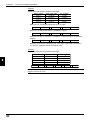
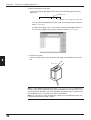
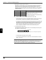
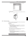
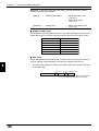
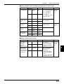
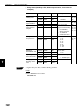
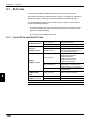
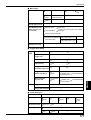
Chapter 8
8.2
PLC Link
Setting the BL-600 and PLC
This section describes setting the BL-600 Series and the PLC.
8.2.1 Setting the BL-600 Series
Use the BL-600 setup software to set the following. For the differences in setting
due to the link unit or PLC type, see the next subsection “Setting the PLC”.
1. In [[Comm settings-1]], set the following data.
•
Match the baud rate, data length, parity and stop bit length of the BL-600 to
those of the PLC.
•
Disable the RTS/CTS protocol.
•
Disable the multi-drop link.
2. In [[Comm settings-2]], set the following data.
•
Type of the PLC
When using the KV-L2* in “Display interface mode”, set “SYSMAC-C” in the
BL-600 settings.
•
PLC trigger input area
•
DM head address
•
PLC unit No./station No.
•
Set whether or not the final register is used.
8.2.2 Setting the PLC
Set the PLC or link unit as follows:
■ Setting MELSEC-A Series
1. Set the RS-232C communication parameters (baud rate, data length, parity and
stop bit length) according to the BL-600’s settings.
8
2. Set the station number according to the BL-600’s setting.
3. Set the mode to “Protocol Type 4 ”.
* Only for the AJ71QC24, set the mode to “Special protocol”, “ASCII”, and
“Type4”.
4. Set the main channel to either “RS-232C” or “RS-422A”.
5. Set “Checksum” to “Enable”.
6. Set “Write during running” to “Enable”.
7. Set “Selecting computer link/multi-drop” to “Computer link” (for the AJ71UC24
only).
132