1
Chapter 5
Installation
This chapter describes the procedure and cautions for the installation of the BL-600
Series and special power supply unit.
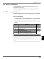
5.1
Installation of the BL-600 Series ........................................ 72
5.1.1
5.1.2
5.1.3
5.1.4
5.1.5
Situations to check for before installing the BL-600 Series ... 72
Mounting angle and distance ................................................. 74
Mounting the BL-600/601/600HA/601HA .............................. 75
Mounting the BL-650HA/651HA ............................................ 77
Mounting the BL-600 Series without the mounting bracket ... 79
5.2
Installation of the Special Power Supply Unit ................... 81
5.2.1 In-panel installation ................................................................ 81
5.2.2 Installing the BL-U1 ............................................................... 81
5.2.3 Installing the BL-U2 and N-42 ................................................ 83
Chapter 5
5.1
Installation
Installation of the BL-600 Series
This section describes situations to check for before installing the BL-600 Series,
and the installation procedure.
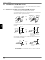
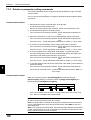
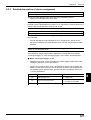
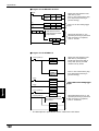
5.1.1 Situations to check for before installing the BL-600 Series
Check the following points before installing the BL-600 Series.
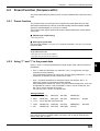
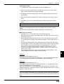
Avoid extraneous light from entering the transmitter/receiver of the BL-600 Series.
Otherwise, the reading may fail or be unreliable.
Change the position
of the sensor.
Cut off the
extraneous light.
Remedy
Photoelectric sensor
;;
;;
;;
;
;
;
;
If something interrupts the emitted or reflected laser beam, the reading may be
unreliable.
5
Bar code
Light-shielding
object
Remedy
Reflected
beam
Change the position of the lightshielding object to ensure passage
of the laser beam.
If the laser beam reflects the bar code at a right angle (specular reflection), the
reading may fail or be unreliable.
Emitted
laser beam
Remedy
15°
Reflected
laser beam
Be sure to apply the laser beam at
some angle.
*
72
Since the BL-650HA/651HA emits a laser beam at an angle of 17°, tilting the
unit is unnecessary.
Chapter 5
Installation
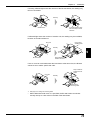
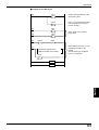
If a strong reflected light enters the receiver of the BL-600 Series, the reading may
fail or be unreliable.
Remedy
;;
;;;;
;;
Cover the metal surface
with black tape to avoid
reflection.
Metal surface
If reflected light enters the receiver of another unit, the reading may be unreliable,
because of mutual interference.
Place a lightshielding plate.
Bar code
Remedy
5
Keep a distance
between the units.
BL-600 Series
If two or more bar code labels enter the laser beam at the same time, the BL-600
cannot be set to read a specific bar code.
Keep a distance
between the bar
codes.
Bar code
Remedy
Decrease the
scanning width.
➮
See page 67 to change the scanning width.
*
When “Multi-label read mode 3” is specified, the BL-600 Series can simultaneously read up to 4 bar codes in the field of the laser beam.
73
Chapter 5
Installation
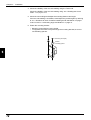
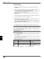
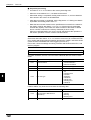
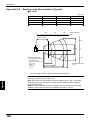
5.1.2 Mounting angle and distance
The BL-600 Series must be installed so that the laser beam is applied at an angle
of approximately 15° with reference to a line perpendicular to the target. This
means that the BL-600/601/600HA/601HA must be tilted at an angle of 15°. Since
the BL-650HA/651HA emits a laser beam at an angle of 17°, tilting the unit is
unnecessary.
Refer to the read range and angle characteristics on pages 148 to 150 for the
appropriate mounting angle and distance for the BL-600 Series.
Normally, the BL-600 Series provides the best reading stability when mounted at
the following angle and distance.
BL-600/601/600HA/601HA
Reading distance
BL-650HA/651HA
Reading distance
15°
17°
Reading distance
BL-600/601: 120 mm
BL-600HA/601HA: 90 mm
Reading distance
BL-650HA/651HA: 65 mm
5
*
*
*
The supplied mounting bracket facilitates the angle setting. (➮ See pages 75 to 78.)
The reading rate check mode (➮ See pages 94 to 96.) ensures an optimal reading
position.
The laser beam application angle for the BL-650HA/651HA is 17° ±3° with
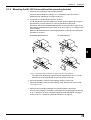
reference to a line perpendicular to the rear surface of the unit.
Note 1: Do not mount the BL-600 Series so that the laser beam is applied to bar
codes at a right angle (±10°). Otherwise, the specular reflections may cause
unstable reading or reading errors. (➮ See page 151.)
BL-600/601/600HA/601HA
BL-650HA/651HA
17°
Within ±10°
Within ±10°
Incorrect
Incorrect
Note 2: The reading distance and angle may vary depending on the narrow bar
width, size, and printing quality of bar codes. Be sure to test the BL-600 Series’
ability to read the actual bar codes using “Reading rate check mode” on pages 94
to 96.
74
Chapter 5
Installation
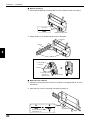
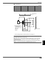
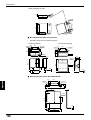
5.1.3 Mounting the BL-600/601/600HA/601HA
The following is the procedure for mounting the BL-600/601/600HA/601HA with the
supplied mounting bracket. To mount the BL-600 Series without the mounting
bracket, refer to “Mounting the BL-600 Series without the mounting bracket” on
pages 79 and 80.
1. Check the surroundings of the mounting position.
Check the surroundings according to “Situations to check for before installing
the BL-600 Series” on pages 72 and 73.
2. Attach the BL-600 Series to the mounting bracket.
➮ Refer to page 155 for the dimensions of the mounting bracket.
When bracket A is used
When bracket B is used
Supplied mounting
screw (M3)
Laser beam
Mounting bracket B
Laser beam
Supplied mounting
screw (M3)
Mounting bracket A
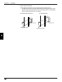
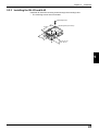
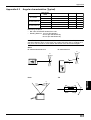
3. Temporarily fix the mounting bracket.
The angle of the laser beam application is 15° when the BL-600 Series is
secured to the mounting bracket as shown below.
➮ See “5.1.2 Mounting angle and distance” on page 74 for the mounting distance.
When mounting bracket A is used:
When mounting bracket B is used:
Bar code
Bar code
BL-600 Series
BL-600 Series
15°
15°
Perpendicular
line
Mounting bracket
Bar code
Mounting
bracket
Mounting bracket
Perpendicular
line
Bar code
Mounting
bracket
75
5
Chapter 5
Installation
4. Check the reliability of the bar code reading using the Test mode.
Check the reliability of the bar code reading using “Reading rate check mode”.
➮ See pages 94 to 96.
5. Check the surroundings and adjust the mounting distance and angle.
If the bar code reading is unreliable, check/adjust the position again by referring
to “5.1.1 Situations to check for before installing the BL-600 Series” on pages
72 and 73 and “5.1.2 Mounting angle and distance” on page 74.
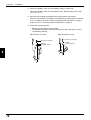
6. Fasten the mounting bracket.
*
*
Mounting screws (M4) are not included.
To suppress the noise conveyed through the mounting bracket, be sure to
use insulating spacers.
When bracket A is used
Mounting screw (M4)
Washer
Insulating spacer
5
76
When bracket B is used
Mounting screw (M4)
Washer
Insulating spacer
Chapter 5
Installation
5.1.4 Mounting the BL-650HA/651HA
The following is the procedure for mounting the BL-650HA/651HA with the supplied
mounting bracket. To mount the BL-600 Series without the mounting bracket, refer
to “Mounting the BL-600 Series without the mounting bracket” on page 79.
1. Check the surroundings of the mounting position.
Check the surroundings according to “5.1.1 Situations to check for before
installing the BL-600 Series” on pages 72 and 73.
2. Attach the BL-600 Series to the mounting bracket.
*
The mounting bracket for the BL-650HA/651HA allows two mounting orientations. Choose the appropriate orientation according to the application.
➮ Refer to page 155 for the dimensions of the mounting bracket.
Laser beam
Laser beam
Mounting bracket
Mounting bracket
Supplied mounting
screw (M3)
Supplied mounting
screw (M3)
3. Temporarily fix the mounting bracket.
Since the BL-650HA/651HA emits a laser beam at an angle of 17°, install the
unit parallel to the surface of the bar code as shown below.
➮ See “5.1.2 Mounting angle and distance” on page 74 for the mounting distance.
*
The laser beam application angle for the BL-650HA/651HA is 17° ±3° with
reference to a line perpendicular to the rear surface of the unit.
BL-650HA/651HA
BL-650HA/651HA
Bar code
Bar code
Parallel
Parallel
Mounting bracket
Mounting bracket
Bar code
Bar code
BL-650HA/651HA
BL-650HA/651HA
Mounting bracket
Mounting bracket
77
5
Chapter 5
Installation
4. Check the reliability of the bar code reading using the Test mode.
Check the reliability of the bar code reading using “6.4.1 Reading rate check
mode”. ➮ See pages 94 to 96.
5. Check the surroundings and adjust the mounting distance and angle.
If the bar code reading is unreliable, check/adjust the position again by referring
to “5.1.1 Situations to check for before installing the BL-600 Series” on pages
72 and 73 and “5.1.2 Mounting angle and distance” on page 74.
6. Fasten the mounting bracket.
*
*
Mounting screws (M4) are not included.
To suppress the noise conveyed through the mounting bracket, be sure to
use insulating spacers.
Mounting screw (M4)
Washer
Insulating spacer
5
78
Chapter 5
Installation
5.1.5 Mounting the BL-600 Series without the mounting bracket
1. Check the surroundings of the mounting position.
Check the surroundings according to “5.1.1 Situations to check for before
installing the BL-600 Series” on pages 72 and 73.
2. Temporarily mount the BL-600 Series in position.
The BL-600 Series must be installed so that laser beam is applied at an angle of
approximately 15° with reference to a line perpendicular to the target.
This means that the BL-600/601/600HA/601HA must be titled at an angle of 15°.
Since the BL-650HA/651HA emits a laser beam at an angle of 17°, tilting the unit
is unnecessary.
Mount the BL-600 Series in the following orientation according to the laser beam
orientation to be used.
BL-600/601/600HA/601HA
BL-650HA/651HA
5
➮ See “5.1.2 Mounting angle and distance” on page 74 for the mounting distance.
*
The laser beam application angle for the BL-650HA/651HA is 17° ±3° with
reference to a line perpendicular to the rear surface of the unit.
3. Check the reliability of the bar code reading using the Test mode.
Check the reliability of the bar code reading using “Reading rate check mode”.
➮ See pages 94 to 96.
4. Check the surroundings and adjust the mounting distance and angle.
If the bar code reading is unreliable, check/adjust the position again by referring
to “5.1.1 Situations to check for before installing the BL-600 Series” on pages
72 and 73 and “5.1.2 Mounting angle and distance” on page 74.
79
Chapter 5
Installation
5. Fasten the BL-600 Series.
Fasten the BL-600 Series in the mounting position with M3 screws.
* The M3 screws are not included. Select the M3 screws after checking the
panel thickness and other factors of the mounting position. (The mounting
hole for the BL-600 Series is 4 mm deep.)
BL-600/601/600HA/601HA
BL-650HA/651HA
Mounting hole
Mounting hole
Mounting screw (M3)
5
80
Mounting screw (M3)
Chapter 5
5.2
Installation
Installation of the Special Power Supply Unit
This section describes how to install the special power supply units BL-U1, BL-U2,
and N-42.
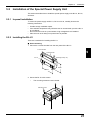
5.2.1 In-panel installation
To mount the power supply unit BL-U1, BL-U2 or N-42, carefully observe the
following instructions.
•
•
•
•
Provide enough ventilation space.
If the ambient temperature may fall below 0°C or exceed 50°C, provide a fan or
air conditioner.
Do not mount this unit in a panel where a high voltage device is installed.
Place this unit as far away from power lines as possible.
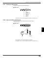
5.2.2 Installing the BL-U1
There are 2 methods for installing the BL-U1.
■ Screw mounting
1. Pull out the 4 screw slot tabs from the rear panel of the BL-U1.
Pull out the tab.
5
Screw hole tab
Mounting hole (4-ø5)
BL-U1
98mm
150mm
2. Secure the BL-U1 with screws.
*
The mounting screws are not included.
Mounting screw
81
Chapter 5
Installation
■ DIN-rail mounting
1. Check that the DIN-rail mounting claw is in the condition shown in the figure.
Front view
DIN-rail mounting claw
2. Attach the BL-U1 to the DIN rail as shown in the figure.
Fixed claw
DIN rail
5
Mounting the BL-U1 to a DIN-rail
1. Hook the BL-U1
to the rail.
DIN rail
Fixed claw
2. Push the bottom
of the BL-U1
against the rail.
Mounting claw
■ Removal from a DIN rail
1. Pull the mounting claw down until it is in position B. Disengage the BL-U1 from
the DIN rail.
2. After removal, push the mounting claw back to position A.
A
B
Mounting claw
Pull the claw down using
a screwdriver, etc.
82
Chapter 5
Installation
5.2.3 Installing the BL-U2 and N-42
Install the BL-U2 and N-42 using screws through the mounting holes.
* The mounting screws are not included.
Mounting screw
63.2mm
Mounting hole (2-ø4.5mm)
43.2mm
BL-U2: 21 mm
N-42: 26 mm
5
83
Chapter 5
5
84
Installation
Chapter 6
Functions for Reading Operation
This chapter describes the reading operation and other functions, such as test
mode, of the BL-600 Series.
6.1
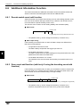
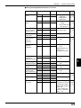
Read Operation .................................................................... 86
6.1.1 Scanning method ................................................................... 86
6.2
Read Modes .......................................................................... 88
6.2.1
6.2.2
6.2.3
6.2.4
Single label read mode .......................................................... 88
Multi-label read mode 1 (Multi 1) ........................................... 89
Multi-label read mode 2 (Multi 2) ........................................... 90
Multi-label read mode 3 (Multi 3) ........................................... 91
6.3
Label Orientation Mode ....................................................... 93
6.4
Test Mode ............................................................................. 94
6.4.1 Reading rate check mode ...................................................... 94
6.4.2 Tact check mode ................................................................... 97
6.4.3 Online test mode .................................................................... 99
6.5
Preset Function (Compare with:) ..................................... 101
6.5.1 Preset function ..................................................................... 101
6.5.2 Using “?” and “!” in the preset data ...................................... 101
6.6
Additional Information Function ...................................... 102
6.6.1 Decode match count add function ....................................... 102
6.6.2 Scan count add function
(valid only if using the decoding count add function) ........... 102
6.6.3 Code type add function ........................................................ 103
6.6.4 Label orientation add function .............................................. 103
6.6.5 Symbology ID add function .................................................. 104
6.6.6 PMI add function .................................................................. 104
6.6.7 Order of the additional information ...................................... 106
6.7
Max. Code Length (Designated Digit )
Output Function ................................................................. 107
Chapter 6
6.1
Functions for Reading Operation
Read Operation
This section describes the scanning methods of the BL-600 Series.
6.1.1 Scanning method
There are two methods to trigger the BL-600 Series to read bar codes: the “Level
signal” method and the “One-shot signal” method. Select an appropriate method
according to the application. Typically, the “Level signal” method is used.
The following examples for these two methods use the “6.2.1 Single label read
mode”. ➮ See page 88.
Level signal trigger
When the trigger input turns on, the BL-600 Series starts laser emission to read the
bar codes. The laser turns off after the number of the bar code reading reaches the
specified decoding match count. ➮ See page 43. The BL-600 Series then sends the
read data.
Reference 1: The BL-600 Series can read up to 4 types of bar codes without
changing settings. ➮ See page 49.
Reference 2: Pressing the TEST switch lightly (for less than 2 seconds) serves as
a trigger input (The laser turns on once.). ➮ See page 8.
■ Timing diagram
<Succeed to read>
Trigger input
6
<Fail to read>
*1
Bar code
Laser beams
*2
Communication time
*3
OK/NG output
OK/NG *4
NG
*5
*1 Set trigger input so that it stays on long enough for the laser beam to cover the
entire bar code.
*2 The BL-600 Series emits a laser after the trigger input exceeds the preset input
time. ➮ See the following note.
Note: The BL-600 Series has a built-in AGC (auto gain control) circuit. It requires a
maximum of 3 scans (6 ms) to adjust the gain. Therefore, the BL-600 Series
requires a maximum of 6 ms after the laser beam turns on before it begins to read
the data.
*3 The communication time can be obtained from the following expression:
Data bits + (1: If parity is used) + Start/stop bit
Baud rate
(Code length of data to be
X sent + Header/number of
characters in delimiter)
*4 The length of time that the OK/NG output is on can be changed to any value
between the range of 10 ms to 2.55 s. ➮ See page 53.
*5 The OK/NG output turns on 5 ms after the bar code is read.
If the bar code cannot be read, the NG output is delayed by 5 ms plus the
specified input time.
86
Chapter 6
Functions for Reading Operation
Note: 5 seconds after the power switch turns on or an UNLOCK command ( ➮ See
is sent, the unit will not start reading a bar code by turning on the trigger
input.
page 116.)
One-shot signal trigger
The BL-600 Series detects when the trigger input turns on and starts reading bar
codes for the preset “One shot input time”. ➮ See page 44. The laser turns off after the
number of the bar code reading reaches the specified decoding match count.
➮ See page 43. The BL-600 Series then sends the read data.
The rest of the operation is the same as that for the “Level signal” method.
Use the one-shot signal trigger when the one shot input time is extremely short or
to fix the scanning time.
Reference 1: The BL-600 can read up to 4 types of bar codes without changing
the bar code type setting. ➮ See page 49.
Reference 2: Pressing the TEST switch lightly (for less than 2 seconds) serves as
a trigger input (The laser turns on once.). ➮ See page 8.
■ Timing diagram
Trigger input
<Succeed to read>
*1
<Fail to read>
Bar code
Preset input time
Preset input time
Laser beams
Communication time
OK/NG output
OK/NG
6
NG
*1 After the trigger input exceeds the preset input times, the laser begins to emit.
Trigger input minimum ON time:
5 ms (when the trigger input value is 2 ms)
15 ms (when the trigger input value is 10 ms)
Note: The BL-600 has a built-in AGC (auto gain control) circuit. It requires a
maximum of 3 scans (6 ms) to adjust gain. The BL-600 generates a maximum of 6
ms delay until starting to read the data after the laser beam turns ON.
87
Chapter 6
6.2
Functions for Reading Operation
Read Modes
The BL-600 provides 4 types of read modes.
6.2.1 Single label read mode
The single label read mode allows the BL-600 Series to read only one bar code
during one trigger input signal.
■ Data output timing
The BL-600 Series offers the following two data output modes to send data and
output OK/NG signals. Select an appropriate mode according to the application.
Typically, “After Read” is selected.
● After Read ➮ See page 42.
The BL-600 Series sends read data and outputs an OK/NG signal after a
successful read.
This is the operation described in “6.1.1 Scanning methods” on page 86 and
87.
● At trigger input ➮ See page 42.
The BL-600 Series sends read data and outputs an OK/NG signal at the
following timings.
•
For a “Level signal” trigger ➮ See page 86.:
When the trigger input turns off
•
For a “One-shot” trigger ➮ See page 87.:
After the preset input time has passed
6
<Fail to read>
<Succeed to read>
Trigger input
Bar code
Laser beams
Communication time
OK/NG output
*
88
OK/NG
NG
The timing diagram above shows the case for a “Level signal” trigger.
Chapter 6
Functions for Reading Operation
6.2.2 Multi-label read mode 1 (Multi 1)
Multi-label read mode 1 allows the BL-600 Series to continuously read all of the
several bar codes printed on one label during one trigger input signal.
The BL-600 Series outputs the read data every time one bar code is read.
■ Timing diagram
<Succeed to read>
<Fail to read>
Trigger input
Repeat reading time
Bar code
Laser beams
Communication time
OK/NG output
*
*
OK
OK
OK
OK
NG
6
The BL-600 Series continuously reads bar codes in the following periods.
•
For a “Level signal” trigger ➮ See page 86.:
During the trigger input signal
•
For a “One-shot” trigger ➮ See page 87.:
During the preset input time
It is necessary to set the “Repeat-reading time” (➮ See page 42.) to prevent the BL600 Series from reading the same bar code twice.
Set the “Repeat-reading time” longer than the time it takes for the read bar code
to go out of the field of the laser beam (100 ms to 25.5 s).
Note: The same type of bar code cannot be read during the specified repeatreading time. Different types of bar codes can be read continuously during the
period.
*
The OK output turns on every time the BL-600 Series reads a bar code. (Comparison to the preset data is not performed.)
The NG output turns on after the trigger input turns off if the BL-600 Series fails
to read any of the bar codes.
89
Chapter 6
Functions for Reading Operation
6.2.3 Multi-label read mode 2 (Multi 2)
Multi-label read mode 1 allows the BL-600 Series to continuously read all of the
several bar codes printed on one label during one trigger input signal.
*
The number of readable bar codes varies depending on the capacity of the
transmission buffer of the BL-600 Series. ➮ See page 112.
In multi-label read mode 2, all the read data is sent at one time after the trigger
input turns off.
■ Timing diagram
<Succeed to read>
Trigger input
<Fail to read>
Repeat reading
time
Bar code
1 2 3 4 5
Laser beams
Communication time
12345
OK
OK/NG output
*
6
*
NG
The BL-600 Series continuously reads bar codes in the following periods.
•
For a “Level signal” trigger ➮ See page 86.:
During the trigger input signal
•
For a “One-shot” trigger ➮ See page 87.:
During the preset input time has passed
It is necessary to set the “Repeat-reading time” (➮ See page 42.) to prevent the BL600 Series from reading the same bar code twice.
Set the “Repeat-reading time” longer than the time it takes for the read bar code
to go out of the field of the laser beam (100 ms to 25.5 s).
Note: The same type of bar code cannot be read during the specified repeatreading time. Different types of bar codes can be read continuously during the
period.
*
The OK signal turns on if the BL-600 Series reads at least one bar code. (Comparison to the preset data is not performed.)
The NG signal turns on if the BL-600 Series fails to read any of the bar codes.
■ Data format
The read data is sent to the personal computer in the following format.
Header
1st data
,
2nd data
,
3rd data
4th data
,
•••••••
Delimiter
*
Each data packet is separated by a comma (, : 2CH) (intermediate delimiter).
*
The unit sends as many data packets the number of bar codes read.
*
The number of bar codes varies depending on the capacity of the transmission
buffer of the BL-600 Series. ➮ See page 112.
➮ See page 113 for “header string” and “delimiter”.
90
,
Chapter 6
Functions for Reading Operation
6.2.4 Multi-label read mode 3 (Multi 3)
•
Multi-label read mode 3 allows the BL-600 Series to continuously read one of
each of the 4 bar code types, “Code 1” to “Code 4”, as specified in the [[Code
setup]] screen of the setup software (➮ See page 49.) during one trigger input
signal.
*
•
If three types are specified in the [[Code setup]] screen, the BL-600 Series
reads three bar codes. If two types are specified, it reads two bar codes.
Even if several bar codes (4 max.) exist in the field of the laser beam, the BL600 Series can simultaneously read all the bar codes, provided the data of all
the bar codes is different.
The BL-600 Series sends all the read data at one time in the order of “Code 1” to
“Code 4” after the trigger input turns off.
■ Timing diagram
<Succeed to read>
<Fail to read>
Trigger input
Bar Code
Code 1 Code 2 Code 3 Code 4
Laser beams
*
Code 4
Code 3
OK
OK/NG output
*
Code 2
Code 1
Communication time
NG
The BL-600 Series continuously reads bar codes in the following periods.
•
For a “Level signal” trigger ➮ See page 86.:
During the trigger input signal
•
For a “One-shot” trigger ➮ See page 87.:
During the preset input time
6
The OK signal turns on if the BL-600 Series reads all the bar codes specified for
“Code 1” to “Code 4”.(Comparison to the preset data is not performed.)
The NG output turns on if the BL-600 Series fails to read at least one bar code.
■ Data format
The read data is sent to the personal computer in the following format.
Data read
Header from Code
1
,
Data read
from Code
2
,
Data read
from Code
3
,
Data read
from Code Delimiter
4
*
Each data packet is separated by a comma (, : 2CH) (intermediate delimiter).
*
If the reading fails for any one of the Codes 1 to 4, or the corresponding bar
code does not exist, an “ERROR” (➮ See page 112 for the reading error codes.) is sent
instead of the read data.
➮
See page 113 for “header string” and “delimiter”.
91
Chapter 6
Functions for Reading Operation
Example
Suppose that the following codes are specified:
•
“Code” setting
Type of bar code
No. of digits
Code 1
CODE39
10 digits
Code 2
EAN/UPC
13 digits
Code 3
–
–
Code 4
CODE39
8 digits
When the unit successfully reads all 3 types of codes:
Header
•
ABCDE12345
ERROR
KEYENCE1
Delimiter
,
,
4901234567894
KEYENCE1
Delimiter
When the unit fails to read Code 1 (CODE39, 10 digits) and Code 4 (CODE39,
8 digits)
Header
*
,
4901234567894
When the unit fails to read Code 1 (CODE39, 10 digits)
Header
•
,
ERROR
,
4901234567894
,
ERROR
Delimiter
When the same type of data having the same digits is specified to all Codes 1
to 4, the unit sends the data in the reading order.
Example
Suppose that the following codes are specified:
6
“Code” setting
Type of bar code
No. of digits
Code 1
CODE39
7 digits
Code 2
CODE39
7 digits
Code 3
CODE39
7 digits
Code 4
CODE39
7 digits
Header
ABCD123
,
XYZ3333
,
1234567
,
KEYENCE
,
Delimiter
Note: The unit cannot read the bar code having the same content twice while
trigger input turns on once.
92
Chapter 6
Label Orientation Mode
You can specify the orientation of the bar code labels to be read.
The label orientation mode allows the BL-600 Series to only read the bar codes in
the specified orientation if the bar code labels are moving in both the forward and
reverse directions.
Normally, the unit can read bar codes regardless of the orientation. ➮ See page 53.
9000000
9000000
4
Forward
orientation
4
6.3
Functions for Reading Operation
Reverse
orientation
■ Timing diagram
<Specified orientation>
<Non-specified orientation>
Trigger input
Bar code
Laser beams
6
Communication time
OK/NG output
OK/NG
NG
*
The timing diagram above shows the case for the “single label read mode”.
•
A reading error is issued if the BL-600 Series reads a bar code label moving in
an orientation that is not specified.
•
This mode can be used with the desired multi-label read mode. However, the
BL-600 Series does not read bar codes moving in an orientation that is not
specified.
•
You can specify the orientation individually for Codes 1 to 4, such as specifying
“forward orientation” for Code 1, and “reverse orientation” for Code 2.
93
Chapter 6
6.4
Functions for Reading Operation
Test Mode
Test mode can be used for the bar code reading test. The BL-600 Series offers
three types of test mode.
Note: The BL-600 Series continues laser emission during test mode. This can
shorten the service life of the laser. Only select test mode when you need to
perform a reading test.
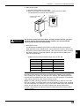
6.4.1 Reading rate check mode
The reading rate check mode is used to measure how many times the BL-600
Series can decode the scanned data while scanning a bar code 100 times.
This mode is useful for the following cases:
● Adjusting the mounting distance and angle
Adjust the mounting distance and angle so that the highest reading rate is
obtained.
● Verifying the reading reliability of the bar code to be used
A high reading rate shows that the printing quality of the bar code is high.
Note: The reading rate check should only be performed for a stationary bar code.
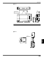
■ Starting method
There are four methods to start the reading rate check mode. Select one of the
following for your convenience.
6
•
•
•
Press the TEST switch of the BL-600 Series.
Use the [[Monitor]] screen of the setup software. ➮ See page 62.
Use the bar code display interface BL-V35E. ➮ See the BL-V35E User’s Manual.
■ Operation
The following instruction uses the TEST switch to start/quit the reading rate check.
All other operations are the same for the other starting methods.
1. Set the mounting distance and angle of the BL-600 Series. ➮ See page 75.
BL-600/601/600HA/601HA
Reading distance
BL-650HA/651HA
Reading distance
15°
17°
Reading distance
BL-600/601: 120 mm
BL-600HA/601HA: 90 mm
Reading distance
BL-650HA/651HA: 65 mm
Note : Do not mount the BL-600 Series so that the laser beam is applied to bar
codes at a right angle (±10°). Otherwise, the specular reflections may cause
unstable reading or reading errors. ➮ See page 151.
BL-600/601/600HA/601HA
BL-650HA/651HA
17°
Within ±10°
Within ±10°
94
Chapter 6
Functions for Reading Operation
2. Start the test mode.
1) Press the TEST switch for 3 seconds.
2) When one STABILITY LED illuminates, release the TEST switch.
The BL-600 Series continues laser emission.
Press the TEST switch
for 3 seconds.
LASER ON
E
S
T
OK/NG
T
TIMING
O
T IM K /N G
IN
G
TEST
LA
SE
RO
N
BL-600
WARNING
Do not look directly at the laser beam. This may result in serious eye injury.
The laser beam is not harmful to the skin; however, do not intentionally
direct the laser beam at the human body.
3. Read the bar code.
The BL-600 Series displays the STABILITY LEDs as shown in the following
table depending on the “Reading rate”, which shows the number of times it can
decode the scanned data while scanning a bar code 100 times. While checking
the display, adjust the mounting distance and angle so that the reading rate
reaches its highest level.
*
ON/NG LED turns ON but OK/NG output does not turn ON.
Reading rate
STABILITY LED
OK/NG LED
81 to 100 %
5 LEDs ON
Green
61 to 80 %
4 LEDs ON
Green
41 to 60 %
3 LEDs ON
Green
21 to 40 %
2 LEDs ON
Green
1 to 20 %
1 LED ON
Green
0%
–
Red
Note1: The higher the reading rate indicated, the more accurately and reliably the
bar code is read. However, this does not mean that the reading is only possible
with a reading rate of 100%. For example, if the reading rate is displayed as 20%,
20 reads were acceptable during the 100 scans. The read operation is not affected
if the scanning time for the bar code is set long enough.
Note2: If a raster-scanning model (BL-601/601HA/651HA) is used for a bar code
with a short height, some laser beams will not be applied to the bar code, resulting
in a low reading rate. For example, if only 4 out of the 8 laser beams of the BL-600
Series can scan the bar code, the highest reading rate obtained will be 50%.
However, this problem can also be solved if the scanning time for the bar code is
set long enough.
95
6
Chapter 6
Functions for Reading Operation
4. The BL-600 Series sends data.
In test mode, the BL-600 Series sends the data in the following format every
100 scans.
Partition mark
Readout data
:
m
m = Reading rate (1 to 100) (Zero-suppressed)
*
You can set the BL-600 Series so that it will not send data while in the test
mode. ➮ See page 54.
*
To check the reading rate on a PC screen, connect the BL-600 Series to a
PC and use the [[Monitor]] screen of the setup software. ➮ See page 62.
5. Quit the test mode.
Press the TEST switch again to quit the test mode. The STABILITY LED turns
off.
6
T
E
S
T
Press once.
O
T IM K /N G
IN
G
LA
SE
RO
N
Note 1: If the additional information function (➮ See pages 102 to 106.) is used while in
the test mode, the BL-600 Series adds the specified data in the same manner as in
normal operation. However, only if the “Reading rate check mode” is selected, will
the “Decoding count” and “Scan count” data not be added.
Note 2: If a PLC link is used, the read data, reading rate, and decoding count are
not written while the test mode is active.
96
Chapter 6
Functions for Reading Operation
6.4.2 Tact check mode
The tact check mode is used to count how many scans the BL-600 Series can
accurately read (decode) while reading a moving bar code.
This mode is useful for the following case:
● Testing the line speed that can be expected before actually implementing the
BL-600 Series on the line
A large decoding number shows that the BL-600 Series can reliably read the
bar code (capable for the line speed).
Note: The tact check should be performed on a moving bar code.
■ Starting method
There are four methods to start the reading rate check mode. Select one of the
following for your convenience.
•
•
•
Press the TEST switch of the BL-600 Series.
Use the [[Monitor]] screen of the setup software. ➮ See page 62.
Use the bar code display interface BL-V35E. ➮ See the BL-V35E User’s Manual.
■ Operation
The following instruction uses the TEST switch to start/quit the reading rate check.
All other operations are the same for the other starting methods.
1. Install the BL-600 Series.
Install the BL-600 Series according to “Chapter 5, Installation” on page 72.
6
2. Start the test mode.
1) Press the TEST switch for 5 seconds.
2) When two STABILITY LED illuminates, release the TEST switch.
The BL-600 Series continues laser emission.
Press the TEST switch
for 5 seconds.
LASER ON
G
/N
IN
O
K
TIMING
T IM
G
T
E
S
T
OK/NG
TEST
LA
SE
RO
N
BL-600
WARNING
Do not look directly at the laser beam. This may result in serious eye injury.
The laser beam is not harmful to the skin; however, do not intentionally
direct the laser beam at the human body.
97
Chapter 6
Functions for Reading Operation
3. Read the bar codes moving on the line.
Depending on the decoding count, the BL-600 Series displays the STABILITY
LEDs as shown in the following table 0.2 seconds after the bar code has
passed the field of the laser beam. By checking the display, you can notice the
reliability that the BL-600 Series ensures during the readout (how capable it is
for the line speed).
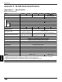
Decoding count STABILITY LED
100 or more
5 LEDs ON
50 to 99
4 LEDs ON
10 to 49
3 LEDs ON
5 to 9
2 LEDs ON
1 to 4
1 LED ON
OK/NG LED
Green
(The readout count equals or exceeds the specified
decoding match count.) ➮ See page 43.
Red
(The readout count is below the specified decoding
match count.) ➮ See page 43.
*
ON/NG LED turns ON but OK/NG output does not turn ON.
*
The BL-600 Series continues to read data while bar codes are in the field of
the laser beam. Therefore, the STABILITY LEDs do not illuminate.
*
If reading bar codes with the same data continuously within 0.2 seconds, the
BL-600 Series cannot differentiate between the data and continues to scan
and add to the decoding count without displaying the STABILITY LEDs. If
the BL-600 Series reads different bar codes within 0.2 seconds of each
other, it displays the STABILITY LEDs to show the decoding count.
4. The BL-600 Series sends data.
The BL-600 Series sends the data to the PC in the following format every time
the STABILITY LEDs illuminate.
Partition mark
6
Readout data
:
m
m = Decoding count (1 to 9999) (Zero-suppressed)
*
A value greater than 9999 cannot be added.
*
You can set the BL-600 Series so that it will not send data while in the test
mode. ➮ See page 54.
Note: It should be judged that the BL-600 Series is capable for the line speed if the
decoding count is always more than 5 to 10. If the decoding count is only 1 or 2,
you need to perform a reading rate check (➮ See pages 94 to 96.) and change the
position of the bar code reader to obtain a higher reading rate.
98
Chapter 6
*
Functions for Reading Operation
To check the reading rate on a PC screen, connect the BL-600 Series to a
PC and use the [[Monitor]] screen of the setup software. ➮ See page 62.
5. Quit the test mode.
Press the TEST switch again to quit the test mode. The STABILITY LED turns
off.
Press once.
TE
ST
O
T IM K /N G
IN
G
LA
SE
RO
N
6
6.4.3 Online test mode
The online test mode allows the BL-600 Series to display the reading reliability in
real time during normal reading operation.
■ Operation
1. Set the online test mode.
1) Send the “#TEST1” command to the BL-600 Series using the [[Monitor]]
screen of the setup software. ➮ See page 62.
2) The setting is completed when a response to the sent command “OK” is
returned from the BL-600 Series.
2. Read bar codes with the BL-600 Series.
After the trigger input turns off, the BL-600 Series sends the read data and
displays the reading reliability with the STABILITY LEDs.
3. Quit the online test mode.
1) Send the “#QUIT” command to the BL-600 Series using the [[Monitor]]
screen of the setup software. ➮ See page 62.
2) The mode is ended when a response to the sent command “OK” is returned
from the BL-600 Series.
Note: The command setting is only effective if the BL-600 Series is turned on. The
setting will be reset when the power is turned off.
99
Chapter 6
Functions for Reading Operation
Reference: To save the online test mode setting in the BL-600 Series, set the
following using the setup software.
• [[Main]]
→ “Additional information”
→ Select “Decoding count”.
➮ See page 43.
→ Select “Scan count”.
➮ See page 43.
• [[Utilities]] → “Stability LED”
→ Select “Use stability LED”.
➮ See page 53.
■ STABILITY LED display
The STABILITY LEDs illuminate as shown in the table, indicating how many times
the BL-600 Series can correctly read (decode) the data of the moving bar codes.
Decoding count
STABILITY LED
100 or more
5 LEDs ON
50 to 99
4 LEDs ON
10 to 49
3 LEDs ON
5 to 9
2 LEDs ON
1 to 4
1 LED ON
0
–
■ Data format
The BL-600 Series appends the number of scans (scan count) and the number of
correctly read bar codes (decoding count) while one trigger input turns on.
6
*
The scan count includes the cases where a bar code does not exist in the field
of the laser beam.
Partition mark
Readout data
:
m
/
s
m = Decoding count (1 to 9999) (Zero-suppressed)
s = Scan count (1 to 9999) (Zero-suppressed)
100
Chapter 6
6.5
Functions for Reading Operation
Preset Function (Compare with:)
This section describes the preset function to prevent different bar codes from being
read.
6.5.1 Preset function
The preset function is the function that compares the preset data (one bar code
data entered beforehand) to the bar code data actually read and outputs OK/NG
signals to indicate whether or not there is a match.
The preset function allows the BL-600 Series to detect different bar codes without
using a PC.
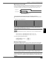
■ OK/NG signal output timing
➮ See pages 86 to 88.
■ Entering the preset data
Use the setup software (➮ See page 53.) or a serial command (➮ See page 128.) to enter
the preset data.
Note: The bar code actually read can be compared to the preset data only in the
single label read mode.
➮ See page 164 if you want to use CODE93.
➮ See page 165 if you want to use CODE128.
6.5.2 Using “?” and “!” in the preset data
Using “?” and “!” in the preset data allows a wider range of bar codes to match the
preset data.
?: One “?” character represents one character. Use “?” to regard any one-digit
character as being matched.
If the preset data is entered as “4912??56”, the two digits positioned in “??” can
contain any characters (numeric values) for a match.
!: One “!” character represents an unlimited number of characters. Use “!” to
regard any number of characters as being matched.
If the preset data is entered as “4912!”, any bar codes that begin with “4912” will
be regarded as a match. If the preset data is “!4912”, any bar codes that end
with “4912” will be regarded as a match.
You can only use “!” once in one preset data.
Setting examples
1. “ABC?”
ABCD (OK),
ABC3 (OK), ABC (NG),
ABCDE (NG)
2. “ABC!”
ABCD (OK),
ABC3 (OK), ABC (OK),
ABCDE (OK),
AB (NB)
3. “?????”
Any 5-digit bar code will be OK.
4. “!CDE”
ABCDE (OK),
3CDE (OK), CDE (OK),
ABBDE (NG),
ADE (NG)
5. “A!E”
ABCDE (OK),
A3CE (OK), ABCD (NG),
AE (OK)
Reference: If you do not register preset data, “!” is automatically registered. Therefore, when the unit successfully reads a bar code, “OK” is output; when the unit
fails to read, “NG” is output.
101
6
Chapter 6
6.6
Functions for Reading Operation
Additional Information Function
This section describes the additional information function that allows the BL-600
Series to send the read data together with various additional data.
6.6.1 Decode match count add function
Adds the number of successful scans during one bar code reading (decode count)
to the end of the readout data (up to 9999 count). However, this decode count is
never less than the preset decoding match count.
This function can be used to check reading stability and code label quality.
■ Data format
Partition mark
:
Readout data
d
d = [Decoding match count] to 9999: Decode count
*
The partition mark (:) can be changed as desired (1 character max.).
■ Data output timing
If the decoding count add function is used, the data is output at a different time
than with normal operation.
•
If single label read mode is used:
The data is always output after the trigger input turns off.
•
If multi-label read mode 1 is used:
The data is output when the repeat-reading time has passed after a bar code
passes across the field of the laser beam.
•
If multi-label read mode 2 or 3 is used:
The operation is the same as when the decoding count add function is not
used.
6
6.6.2 Scan count add function (valid only if using the decoding count add
function)
If the decoding count add function is used, you can add the number of scans while
the trigger input is on, including when the reading has failed and when a bar code
does not exist, to the end of the decoding count (up to 9999).
■ Data format
Partition mark
Readout data
:
d
/
s
s = Scan count (1 to 9999) (Zero-suppressed)
*
102
The partition mark (:) can be changed as desired (1 character max.).
However, the partition mark for the scan count (/) cannot be changed.
Chapter 6
Functions for Reading Operation
6.6.3 Code type add function
Adds the bar code type before the readout data .
■ Data format
Partition mark
t
:
t= 0
1
2
3
4
5
6
7
8
*
Readout data
: CODE39
: ITF
: Industrial 2of5
: Codabar
: EAN/UPC (A•E)
: CODE 128
: COOP 2 of 5
: Read error
: CODE93
The partition mark (:) can be changed as desired (1 character max.).
6.6.4 Label orientation add function
Adds the orientation of bar code travel before the readout data.
➮ See pages 52 and 93
■ Data format
Partition mark
r
:
Readout data
r = F: Forward orientation
R: Reverse orientation
4
9000000
Forward
orientation
9000000
4
6
Reverse
orientation
*
*
If an read error occurs, this information is not added.
The partition mark (:) can be changed as desired (1 character max.).
103
Chapter 6
Functions for Reading Operation
6.6.5 Symbology ID add function
Adds the bar code symbology identifier specified by AIM.
■ Data format
SD
*
Readout data
No partition mark is used.
Bar code type
Symbology identifier
(SD)
]A0
Data specification
No check digit
CODE39
ITF
Inspect check digit (sent).
]A1
Inspect check digit (not sent).
]A3
No check digit
]I0
Inspect check digit (sent).
]I1
Inspect check digit (not sent).
Industrial 2of5
Codabar
UPC/EAN
]I3
–––
]S0
–––
]F0
13-digit EAN
]E0
8-digit EAN
]E4
UPC-A 13-digit format
]E0
UPC-A 12-digit format
None
UPC-E
CODE128
No FNC1
]C0
FNC1 is on the 1st digit of data (EAN-128).
]C1
FNC1 is on the 2nd digit of data.
6
]C2
CODE93
–––
]G0
COOP 2of5
–––
]X0
6.6.6 PMI add function
Adds the data indicating the reading reliability of the bar codes (PMI: Preventive
Maintenance Information).
You can recognize a low reading reliability due to a low printing quality of bar code
labels or a dirty transmitter/receiver of the BL-600 Series, taking appropriate
actions before serious problems can occur.
*
The PMI add function is only available if the single label read mode is used.
■ Data format
Partition mark
Readout data
:
PMI
PM1 = 0 : Normal
1 : Caution
2 : Warning
9 : Reading error
*
104
The partition mark (:) can be changed as desired (1 character max.).
Chapter 6
Functions for Reading Operation
■ Assessment criteria for PMI
The BL-600 Series assesses the PMI (Preventive Maintenance Information) in four
levels by calculating the multiplier for the scan count between laser emission start
and reading completion with reference to the specified decoding match count.
Trigger input
Laser emission
Scan count between laser emission
start and reading completion
The BL-600 Series calculates the PMI using the following calculations.
The assessment uses two reference values (L1: Preset value 1, L2: Preset value
2).
*
Be sure to set L2 larger than L1.
PMI
Calculation
Assessment
0
Scan count/Decoding match count ≤ L1
Normal
1
L1 < Scan count/Decoding match count ≤ L2
Caution
2
L2 < Scan count/Decoding match count
Warning
9
Reading error
Reading error
Note: The scan count includes scans that are not applied to a bar code. If many
scan counts are not applied to a bar code, such as if using a raster-scan type
reader, increase the preset values (L1 and L2).
Example:
When the decoding match count is 2, preset value 1 (L1) is 5, and preset value 2
(L2) is 10:
•
•
Scan count for L1: 2 (Decoding match count) x 5 (L1) = 10
Scan count for L2: 2 (Decoding match count) x 10 (L1) = 20
As a result, PMI is assessed as follows:
•
•
•
10 scans or less
→ PMI = 0
From 11 scans to 20 scans → PMI = 1
21 scans or more
→ PMI = 2
■ Setting the PMI preset values
First, perform a reading rate check. Then, check the result and the following table
to determine the preset values. A reading rate of less than 20% is not included.
Reading rate
Preset value 1
Preset value 2
20% to 39%
6
12
40% to 59%
5
10
60% to 79%
4
8
80% to 100%
3
6
The above values should only be used as a guide. Select the optimal value according to the operating conditions for a more severe or a more moderate criteria.
Reference: When the preset value 1 (L1) is set to “0”, there is no assessment
criteria for preset value 1, so PMI 1 will not be displayed. If the preset value 2 (L2)
is set to “0”, there is no assessment criteria for preset value 2, so PMI 2 will not be
displayed.
105
6
Chapter 6
Functions for Reading Operation
■ Conditions for effective PMI
To use PMI effectively, use the function under the following conditions:
•
Set the BL-600 Series so that it emits the laser after the bar codes have completely entered the field of the laser beam.
If the BL-600 Series emits the laser before the bar codes enter the field of the
laser beam, it will start counting scans with no bar codes, resulting in an inaccurate PMI.
•
Use the PMI add function for stationary or slowly moving bar codes. If the bar
codes move at a fast speed, the scan count for each bar code decreases,
resulting in an inaccurate PMI. Use the function if the decoding count in the tact
check mode (➮ See page 94.) is at least 20.
•
The PMI add function is only effective in “Single label read mode”.
■ Useful examples of PMI applications
● Controlling the printing quality of bar codes
Monitor the PMI constantly. If the PMI value is degraded, the printing quality of
the bar code may have a problem. Inspect the bar code.
● Preventing problems before they happen
If using several BL-600 Series units, monitor the PMI of all the units constantly.
6
•
If the PMI value of a specific unit is degraded:
The unit may have a problem, such as a dirty transmitter/receiver.
•
If the PMI value for a specific bar code is degraded:
The bar code may have a problem, such as a low printing quality.
As shown above, PMI allows you to identify problems. You can take appropriate
action before a reading error actually occurs.
6.6.7 Order of the additional information
If you select to include all the additional information functions, they appear in the
following order:
Symbology
Code type
identifier
:
Label
orientation
Readout
data
:
Decoding
count
:
Scan
count
*
You can change the partition mark as desired (one character), except the
delimiter of the scan count.
*
No partition mark is used for the symbology identifier.
•
If the PMI add function is used, the decoding and scan counts cannot be added.
Symbology
Code type
identifier
106
:
:
Label
orientation
:
Readout
data
:
PMI
Chapter 6
6.7
Functions for Reading Operation
Max. Code Length (Designated Digit ) Output Function
The max. code length output function allows the BL-600 Series to output only the
designated digit(s) to the PC.
For example, you can extract “345” for the output from the bar code data
“49123456”.
Individually set the function for Codes 1 to 4 by the following procedure.
➮ See page 52.
1. Set “Direction”.
Set the direction, “Forward” or “Reverse”, from which you would like to start
counting.
Direction
Forward
Reverse
4 9 1 2 3 4 5 6
2. Set “Starting”.
Specify from which digit you would like to begin selection (designation start
digit) in the direction specified in step 1.
Starting
5th digit by counting forward
4 9 1 2 3 4 5 6
6
3. Set “Effective”.
Specify how many digits you would like to select for output (designation effective digits) starting from the designation start digit specified in step 2.
Effective
3 digits starting from 5th digit by counting forward
4 9 1 2 3 4 5 6
Note 1: The data is output in the forward direction regardless of the selected
direction.
Note 2: When the bar code group includes those having different digits, take
special care on the designated direction when setting the digits to be output.
Example
Designating and outputting “34” from bar codes “158423421” and “58423421”
1 5 8 4 2 3 4 2 1
5 8 4 2 3 4 2 1
Designate 2 digits starting from 3rd digit by counting reversely.
Note 3: When comparing to the preset data, all the digits of the bar code are used.
107
Chapter 6
6
108
Functions for Reading Operation
Chapter 7
Serial Communication
This chapter describes the serial communication control.
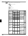
7.1
Serial Communication ....................................................... 110
7.2
Details on Data Communication ....................................... 111
7.3
Command Communication ............................................... 114
7.3.1 Setup of direct control commands ....................................... 114
7.3.2 Details on parameter setting commands ............................. 118
Chapter 7
7.1
Serial Communication
Serial Communication
Serial communication allows you to send the bar code read data from the BL-600
Series to a personal computer, or change the BL-600 Series settings from a personal computer without using the setup software.
Communication types
The BL-600 provides the following two communication types:
•
Data communication
Sends read bar code data from the BL-600 to the PC.
•
Command communication
Changes the BL-600’s settings by sending a command from the PC to the BL600.
*
All communication is performed using ASCII codes on page Appendix 26.
Communication setup
Configure the setup for BL-600 and the PC before attempting serial communication.
7
Tips
•
Setup of BL-600
Set the following parameters for the BL-600 using the setup software.
• Baud rate, Data bits, Parity, Stop bits ➮ See page 45.
• Communication protocol ➮ See pages 45 and 46.
• Header/Delimiter ➮ See page 46.
• Read error code ➮ See page 43.
•
PC setup
Based on the BL-600’s settings, set the communication parameters on the PC
using the “Ports” setting in the Windows Control Panel/System/Device Manager.
•
The following communication parameters are the default settings for the BL-600:
• Baud rate: 9600 bps
• Data bits: 7 bits
• Parity: Even
• Stop bit: 1 bit
Set the PC according to the above settings before attempting communication.
•
•
The BL-600 is set, temporarily, to the default settings for 5 seconds after the power
switch is turned on.
When the current settings of BL-600 is not certain, send the command “SSET” (➮ See
page 116.) and a [CR] to the BL-600 from your PC with 5 seconds after power-up. This
causes the BL-600 to remain at its default settings and you can communicate with the
BL-600 at the default settings. For information on checking the BL-600’s current
settings, see “Sift to setting mode” on page 116.
For information on changing the above communication parameters see “Details on
parameter setting commands” on page 118.
When the BL-600 TEST switch is pressed for 8 seconds, the 1st, 3rd and 5th STABILITY LEDs from the top flash, indicating that the communication parameters are set as
above. (Press the TEST switch again to reset the settings.)
Note: All commands should be entered in all uppercase characters. The BL cannot
accept lowercase characters.
110
Chapter 7
7.2
Serial Communication
Details on Data Communication
This section describes the communication protocols and data format for data
communication.
Communication protocols
The BL-600 supports the following four handshaking protocols (types of data
communication).
T
E
S
T
B
L
-6
0
0
■ No Handshaking
The BL-600 Series sends read data to the PC without any handshaking protocol.
OK
TI M /N G
IN
G
LA
SE
R ON
Read data
■ PASS/RTRY Handshaking
1. The BL-600 Series sends read data to the PC.
2. The BL-600 Series waits for a response from the PC (PASS: Transmission
succeeded, RTRY: Request to re-send).
3. If “PASS” is sent from the PC to the BL-600 Series, the data transmission is
complete. The BL-600 is ready for the next data transmission.
* The BL-600 Series does not respond to the “PASS” command.
4. If the BL-600 Series receives “RTRY” from the PC while waiting for “PASS”, the
BL-600 Series resends the same data and again waits for “PASS”.
* Once the BL-600 Series receives a “PASS”, it will send nothing, even if
“RTRY” is received from the PC.
T
E
S
T
B
L
-6
0
0
5. The BL-600 can continue to read bar codes while waiting for “PASS.” The data
is stored in the BL-600’s transmission buffer. ➮ See page 112.
OK
TI M /N G
IN
G
Read data
LA
SE
R ON
Response
(PASS, RTRY)
Note: If the amount of stored data exceeds the capacity of the transmission buffer,
the BL-600 Series sends “[Header] OVER [Delimiter]” to the PC, and clears all the
data stored in the transmission buffer. In this case, the BL-600 Series will stop
operation. Operation is resumed when the BL-600 Series receives a “PASS” in
response to “[Header] OVER [Delimiter].”
111
7
Chapter 7
Serial Communication
•
PASS and RTRY can be received in either communication format
PASS <CR>(RTRY<CR>) or <STX> PASS <ETX>(<STX>RTRY<ETX>).
* An <ESC> can also be added to the beginning and an <LF> added to the
end of the format.
Note 1: The BL-600 Series can receive all commands while waiting for a “PASS.”
In this case, the BL-600 Series will send back without waiting for a response to the
command (e.g. OK).
Note 2: When the BL-600 Series receives the “SSET” command (➮ See page 116.)
while waiting for a “PASS”, it clears all the data stored in the transmission buffer,
and enters the setting mode.
■ ACK/NAK Handshaking
The ACK/NAK handshaking uses <ACK> (06H) and <NAK> (15H) instead of
“PASS” and “RTRY”, which are used in the PASS/RTRY handshaking. Operation is
the same as that for the PASS/RTRY handshaking, except for the transmission
characters.
■ RTS/CTS Handshaking
• When the PC’s “RTS” (BL-600 series’ CTS) signal turns off, the BL-600 Series
suspends data transmission. When the PC’s “RTS” signal turns on, the BL-600
Series sends the suspended data.
•
The BL-600 Series can still read bar codes even if the PC’s “RTS” signal is off.
In this case, the data is stored in the BL-600 series’ transmission buffer.
➮ See page 112 for its capacity.
Note 1: If the amount of stored data exceeds the capacity of the transmission
buffer, the BL-600 sends back [Header]OVER[Delimiter] to the PC, and clears all
data stored in the transmission buffer. The BL-600 stops operation while clearing
data. It recovers when the RTS of the computer turns ON.
Note 2: The RTS/CTS handshaking cannot be used for RS-422A communication.
Note 3: The RTS/CTS protocol can be used together with other handshaking
protocols.
Note 4: When the PC’s RTS signal is off, the BL-600 does not sends back a
response (e.g. OK [CR]) to the PC.
7
Capacity of transmission buffer
The BL-600’ s transmission buffer can store 400 bytes (400 characters).
The number of characters stored in the transmission buffer for each data packet is
the number of characters in the data (including additional data such as the number
of decoding match count) plus an additional five characters indicating the data’s
attributes.
When multi label reading mode 2 or 3 is used, these five attribute characters are
added to each data packet.
400 ÷ (10 + 5) = 26
400 ÷ (20 + 5) = 16
Attributes of
Capacity of
the transmis- the data
sion buffer
Attributes of
Capacity of
the transmis- the data
sion buffer
The transmission buffer can store 26
pieces of data.
The transmission buffer can store 16
pieces of data.
112
➞
When the number of bar code digits is
20 (with no additional data)
➞
When the number of bar code digits is
10 (with no additional data)
➞
Example 2
➞
Example 1
Chapter 7
Serial Communication
Read data format
Set the data format of the Header and Delimiter, respectively.
Header
Read data
Delimiter
With the setup software, the following formats can be selected. Other than the
following formats, you can freely set up to 5 characters.
Header: <ESC> (1BH), <STX> (02H), None
Delimiter: <CR> (0DH), <CR> (0DH) <LF> (0AH), <ETX> (03H)
Read error code
If the BL-600 Series fails to read a bar code, it sends back a read error code.
The initial setting of the read error code is as follows:
Header
ERROR
Delimiter
The read error code can be changed as desired (within 8 characters).
The BL-600 can be set to send no error code.
➮ See page 43.
7
113
Chapter 7
7.3
Serial Communication
Command Communication
The BL-600 includes commands to directly operate the BL-600 (direct control
commands) and the commands used to change or confirm the BL600’s settings
(parameter setting commands).
7.3.1 Setup of direct control commands
Communication procedure
1. Send a direct control command from the PC to the BL-600.
2. After receiving a command, the BL-600 Series sends back an OK response and
executes the required operation.
*
IN
IM
T
G
N
O
/N
R
SE
LA
OK
Command
G
T
E
S
T
B
L
-6
0
0
*
The BL-600 Series does not send back a response for the read operation
and test mode control commands.
When an incorrect command is sent to the BL-600, the BL-600 sends back
no response.
Response
Communication format
When the command format is [Command][CR], the response format is
[Response][CR]. When the command format is [STX][Command][ETX], the
response format is [STX][Response][ETX].
7
*
Command
Response
Command CR
Response CR
STX Command ETX
STX Response ETX
<LF> can be added after the command being sent. In this case, however, <LF>
is not added to the response data.
Note 1: When <ESC> is inserted before the command being sent, characters in
the BL-600’s command receiving buffer are cleared.
Note 2: If the BL-600’s command receiving buffer contains erroneous characters
due to data transmission error during communication, add <ESC> to the command
being sent.
Note 3: For command communication, set the time duration between transmission
of each character (byte) to up to 30 seconds. If this duration exceeds 30 seconds,
the BL-600 cancels the received characters.
114
Chapter 7
Serial Communication
Explanation of direct control commands
The following describe direct control commands in details.
Read operation control
This command specifies the data read timing.
● Trigger on
Command: LON
Response: None
● Trigger off
Command: LOFF
Response: None
•
Even when the read operation is controlled with these commands, the BL-600
performs the same operation as with the trigger input. ➮ See pages 86 to 93.
“Trigger input: on” corresponds to LON, and “trigger input: off” corresponds to
LOFF.
•
The BL-600 Series starts reading bar codes on receipt of LON and stops
reading on receipt of LOFF.
If the bar codes are properly read and the read data is sent back, you do not
need to send LOFF.
•
The command characters can be freely changed (within 8 characters).
Test mode control
Starts or quits the test mode.
● Reading rate check
Command: TEST1
Response: None
● Tact check
Command: TEST2
Response: None
7
● Resetting test
Command: QUIT
Response: None
•
After using the test mode, be sure to reset it.
OK/NG output control
Directly turns on/off the OK/NG output.
This enables you to easily check wiring.
● Turning the OK output on
Command: OKON
Response: OK
● Turning the NG output on
Command: NGON
Response: OK
● Turning the OK/NG outputs off
Command: ALLOFF
Response: OK
115
Chapter 7
Serial Communication
Online test mode
Sets to online test mode. ➮ See pages 99 and 100.
● Online test ON
Command: #TEST1
Response: OK
● Online test OFF
Command: #QUIT
Response: OK
Clearing transmission buffer
Clears data stored in the transmission buffer.
Command: BCLR
Response: OK
Shift to setting mode
Enters the setting mode. ➮ See page 118.
Command: SSET
Response: OK
Laser off/Resetting Laser off
Turns off the laser emission when the laser beam may cause injury to an operator.
➮ See page 4.
● Laser off
Command: LOCK
Response: OK
● Resetting Laser off
Command: UNLOCK
Response: OK
7
•
When the Laser off command is executed, bar code read operation (laser
emission) is disabled until the Laser off command is reset by using UNLOCK
command.
•
The Laser off command is retained even after the power is turned off.
Reset
Resets the BL-600 software.
Command: RESET
Response: OK
116
Chapter 7
Serial Communication
Readout history check
Outputs the readout OK and NG counts during trigger input ON.
•
Command: NUM
Response: aaaaa/bbbbb/ccccc
aaaaa = 00000 to 65535: Readout OK count
bbbbb = 00000 to 65535: Readout NG count
ccccc = 00000 to 65535: Trigger input ON count
These counts are reset to zero by turning the power OFF or sending the RESET
command.
Motor control
Stops motor rotation.
● Motor stop
Command: MOTOROFF
Response: OK
● Resetting the motor stop
Command: MOTORON
Response: OK
•
Reading is disabled for 5 seconds after the motor stop is reset.
Changing the scanning width
Changes the scanning width
● Starting angle of scanning
Command: SDEGa
(Specify the starting angle of scanning [angle “a”] using angle “c” as a reference.) [a = 0 to 400 (Unit: 0.1°) * Initial value = 0]
Response: OK
● Scanning angle
Command: WDEGb
(Specify the scanning angle starting from angle “a.”) [b = 400 to 600 (Unit: 0.1°)
* Initial value = 600]
Response: OK
d
c
60°
b
60°
a
60°
Note 1: The scanning width cannot be specified to exceed the angle range between “c” and “d” (60°).
Note 2: The angle specified in the steps above should be used as a guide. If a
precise setting is required, adjust the position of each bar code reader separately
after installation.
117
7
Chapter 7
Serial Communication
7.3.2 Details on parameter setting commands
The following describes how to change the BL-600’s settings through command
communication.
You can use the setup software to change the BL-600’s settings instead of these
commands.
Communication details
1. Send the direct control command SSET to the BL-600.
The BL-600 will shift to setting mode.
After successfully executing the command, the BL-600 sends back an OK.
2. The BL-600 Series shifts to the setting mode.
If the command is successfully executed: The BL-600 Series sends back an
“OK.”
3. Send the command for an item to be changed (setting change command).
If the command is successfully executed: The BL-600 Series sends back an
“OK.”
If an error occurs: The BL-600 Series sends back an “ERR** (**: Error code).”
4. To confirm the current settings, send a setting confirmation command.
If the command is successfully executed: The BL-600 Series sends back the
setting data.
If an error occurs: The BL-600 Series sends back an “ERR** (**: Error code).”
5. To save the settings in the EEP-ROM, send “SAVE” to the BL-600 Series.
Once the settings have been saved in the EEP-ROM, the BL-600 Series will
start with the new settings the next time it is turned on.
If the command is successfully executed: The BL-600 Series sends back an
“OK.”
If an error occurs: The BL-600 Series sends back an “ERR** (**: Error code).”
6. To quit the setting mode and perform normal bar code reading, send “SEND” to
the BL-600 Series.
If the command is successfully executed: The BL-600 Series sends back an
“OK.”
If an incorrect command is sent: The BL-600 Series sends back an “ERR** (**:
Error code).”
7
Communication format
When the command format is [Command][CR], the response format is
[Response][CR]. When the command format is [STX][Command][ETX], the
response format is [STX][Response][ETX].
*
Command
Response
Command CR
Response CR
STX Command ETX
STX Response ETX
<LF> can be added at the end of the command being sent. In this case, however, <LF> is not added to the response data.
Note 1: When <ESC> is added before the command being sent, characters in the
BL-600’s command receiving buffer are cleared.
Note 2: If the BL-600’s command receiving buffer contains erroneous characters
due to a data transmission error during communication, add <ESC> to the command being sent.
Note 3: For command communication, set the time duration between transmission
of each character (byte) to up to 30 seconds. If this duration exceeds 30 seconds,
the BL-600 cancels the received characters.
118
Chapter 7
Serial Communication
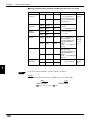
Response error code
When an incorrect command is sent to set parameters, the BL-600 sends back
data indicating the cause of the error (error code). For the commands corresponding to the error codes, see the error code column given in the table on the following
pages.
Error code
Cause of error
00
Undefined command.
01
Command format is incorrect.
02
Nothing corresponds to the number in the command.
03
“m” value (codes 1 to 4) is other than 0 to 3.
04
“Bar code type setting command” was not sent first. ➮ See page 120.
Sending “No. of readable digits setting command” is invalid for UPC/EAN
code.
05
The number in the command is too long.
06
“hhh...” data is too short.
07
“n” value is not 0 or 1.
08
“n” value is exceeding the setting range.
09
“nnn” or “nn” value is exceeding the setting range.
10
“hhh...” is not specified in HEX (hexadecimal) code.
11
“hhh...=FF” cannot be set.
12
“hhh...” or “aaa...” contains more than the specified number of characters.
13
Characters of “aaa...” are invalid.
14
Data in the EEPROM may be damaged. Perform initial setup.
15
Error in the area storing initial settings.
Settings are automatically initialized.
17
7
\ is not followed by !, ? or \ in preset data.
➮ See pages 164 and 165.
18
Two !s exist in preset data. ➮ See page 101.
99
The BL-600 may malfunction. Contact KEYENCE.
119
Chapter 7
Serial Communication
Description of parameter setting commands
■ Saving/initializing settings/quitting setting mode
Function
Command
being sent
Response
Description
Error
code
Saves settings in
the EEP-ROM.
SAVE
OK
➮ See page 118.
–
Initializes settings.
DFLT
OK
Returns to the default-settings,
and saves the settings in the
EEP-ROM.
Quits the setting
mode.
SEND
OK
➮ See page 118.
00, 05,
14, 15
–
■ Setting bar code type and number of readable digits for codes 1 to 4
The following describes the parameter setting commands for Codes 1 to 4.
Be sure to send “Bar code type setting command” first before setting other parameters.
*
When “Bar code type setting command” is newly sent, all other parameters for
the specified code will return to the default settings.
In this case, set all other parameters again.
Setting change commands and setting confirmation commands are described on
the following pages.
Function
Command being
sent
Response
Description
Setting bar code
type for codes 1 to
4.
(Bar code type
setting command)
Change
CODEm=n
OK
m=0 to 3:Codes 1 to 4 00, 01,
Confirm
CODEm
mn
n=0: CODE 39
1: ITF
Error
code
03, 05,
08, 14
2: Industrial 2 of 5
3: Codabar
4: UPC/EAN
5: CODE128
7
6: COOP2of5
7: None
8: CODE93
Setting Max. No. of Change
readable digits
Confirm
MAXm=nn
OK
m=0 to 3: Codes 1 to 4 00, 01,
MAXm
mnn
nn=01 to 32
03, 04,
* For CODE39,
05, 09,
Codabar: 03 to 32
14
* For ITF: 02 to 32
* For CODE128:
01 to 64
120
Setting Min. No. of
readable digits
Change
MINm=nn
OK
Confirm
MINm
mnn
CODE39 Sending
start/stop character.
Change
WCm00n
OK
m=0 to 3: Codes 1 to 4 00, 02,
Confirm
RCm00
00n
n=0: Disable
03, 04,
1: Enable
05, 07,
CODE39 Inspection of check digit
(Modulus 43)
Change
WCm01n
OK
m=0 to 3: Codes 1 to 4 14
Confirm
RCm01
01n
n=0: Disable
Note: With EAN code,
this command causes
error.
1: Enable
Chapter 7
Function
Command being
sent
CODE39
Sending check
digit.
Change
WCm02n
OK
m=0 to 3: Codes 1 to 4 00, 02,
Confirm
RCm02
02n
n=0: Disable
03, 04,
1: Enable
05, 07,
WCm10n
OK
m=0 to 3: Codes 1 to 4 14
WCm10
10n
n=0: Disable
ITF
Change
Inspection of check
digit (Modulus 10/ Confirm
Wait 3)
Response
Serial Communication
Description
Error
code
1: Enable
ITF
Sending check
digit.
Change
WCm11n
OK
m=0 to 3: Codes 1 to 4
Confirm
RCm11
11n
n=0: Disable
Codabar
Sending start/stop
character.
Change
WCm30n
OK
m=0 to 3: Codes 1 to 4
Confirm
RCm30
30n
n=0: Disable
Codabar
Start/Stop
character type
Change
WCm31n
OK
m=0 to 3: Codes 1 to 4
Confirm
RCm31
31n
n=0: Lower case
WCm32n
OK
m=0 to 3: Codes 1 to 4
RCm32
32n
n=0: Disable
1: Enable
1: Enable
1: Upper case
Change
Codabar
Inspection of check Confirm
digit
Change
Codabar
Sending check digit Confirm
1: Enable
WCm33n
OK
m=0 to 3: Codes 1 to 4
RCm33
33n
n=0: Disable
1: Enable
Codabar
Setting check digit
type
Change
WCm34n
OK
m=0 to 3: Codes 1 to 4 00, 02
Confirm
RCm34
34n
n=0: Modulus16
03, 04,
1: Modulus 11
05, 08,
2: Modulus 10/Wait 2 14
3: Modulus 10/Wait 3
4: 7 Check DR
5: Modulus 11-A
6: Modulus 10/
7
Wait 2-A
EAN/UPC (A•E)
Reading UPC-E
EAN/UPC (A•E)
Reading EAN 8
digits
Change
WCm40n
OK
m=0 to 3: Codes 1 to 4 00, 02,
Confirm
RCm40
40n
n=0: Disable
03, 04,
1: Enable
05, 07,
Change
WCm41n
OK
m=0 to 3: Codes 1 to 4 14
Confirm
RCm41
41n
n=0: Disable
1: Enable
121
Chapter 7
Serial Communication
Function
Command being
sent
EAN/UPC (A•E)
Reading JAN 13
digits
Change
WCm42n
OK
m=0 to 3: Codes 1 to 4 00, 02,
Confirm
RCm42
42n
n=0: Disable
03, 04,
1: Enable
05, 07,
EAN/UPC (A•E)
No. of UPC-A
output digits
Change
WCm43n
OK
m=0 to 3: Codes 1 to 4 14
Confirm
RCm43
43n
n=0:Output in 13 digits
➮ See p. 32.
Setting max. code
length output
function
OK
m=0 to 3: Codes 1 to 4
44n
n=0: Disable
Error
code
1: Enable
WCm51n
OK
m=0 to 3: Codes 1 to 4
Confirm
RCm51
51n
n=0: Disable
1: Enable
Change
WCm83n
OK
m=0 to 3: Codes 1 to 4
Confirm
RCm83
83n
n=0: Disable
1: Enable
WCm84n
OK
m=0 to 3: Codes 1 to 4
RCm84
84n
n=0: Forward
WCm85nn
OK
m=0 to 3: Codes 1 to 4 00, 02,
RCm85
85nn
nn=01 to 32
WCm86nn
OK
m=0 to 3: Codes 1 to 4 14
RCm86
86nn
nn=01 to 32
Setting label
orientation specified reading
Change
WCm81n
OK
m=0 to 3: Codes 1 to 4 00, 02,
Confirm
RCm81
81n
n=0: Disable
03, 04,
1: Enable
05, 07,
Setting orientation
for orientationspecified reading
Change
WCm82n
OK
m=0 to 3: Codes 1 to 4 14
Confirm
RCm82
82n
n=0: Forward
Change
Setting effective
digits for max. code Confirm
length output
Setting starting digit Change
for max. code
Confirm
length output
122
WCm44n
RCm44
Change
Setting direction for Change
max. code length
Confirm
output
7
Description
1:Output in 12 digits
Change
EAN/UPC (A•E)
Adding “0” to UPC- Confirm
E system code
CODE128
EAN-128 support
Response
1: Reverse
: Effective digits
03, 04,
05, 09,
: Starting digit
1: Reverse
Chapter 7
Serial Communication
■ Setting Reading Mode/Data Addition Functions
Function
Command being
sent
Response
Description
Setting reading
mode
Change
WP12n
OK
n=0: Single label
Confirm
RP12
12n
Error
code
00, 02,
1: Multi label 1
05, 07,
2: Multi label 2
14
3: Multi label 3
Setting data send
timing
Change
WP13n
OK
Confirm
RP13
13n
N=0: Sends data after 00, 02,
reading
05, 07,
1: Sends after timing 14
input turns off
Setting repeat-read Change
time in multi label
Confirm
reading mode 1 or 2
WP41nnn
OK
nnn=001 to 225
00, 02,
RP41
41nnn
(by 100 ms step)
05, 09,
nnn=001 to 225
14
Setting decoding
match count
Change
WP43nnn
OK
Confirm
RP43
43nnn
Setting decoding
match count in
additional
information
Change
WP10n
OK
Confirm
RP10
10n
Setting scans in
additional
information
Change
WP11n
OK
Confirm
RP11
11n
n=0: No addition
1: Add
00, 02,
05, 07,
14
n=0: No addition
1: Add
Note: Effective only
when No. of
decodings are added.
Change
Setting label
orientation in
Confirm
additional information
Setting code type in Change
additional information Confirm
WP14n
OK
RP14
14n
WP17n
OK
RP17
17n
Adding a symbol
identifier
Change
WP80n
OK
Confirm
RP80
80n
Adding PMI (Preventive maintenance information)
Change
WP86n
OK
Confirm
RP86
86n
PMI Preset value
1 (L1)
Change
WP48nnn
OK
Confirm
RP48
48nnn
PMI Preset value 2
(L2)
Change
WP49nnn
OK
Confirm
RP49
49nnn
Setting reading
error code
Change
WP55hhh...
Confirm
RP55
n=0: No addition
1: Add
7
n=0: No addition
1: Add
n=0: No addition
1: Add
n=0: No addition
1: Add
nnn= 000 to 100
00, 02,
05, 07,
nnn= 000 to 100
14
OK
hhh ... = Reading error
00, 02,
55hhh...
code (within 8 characters) 05, 06,
* Specify the charac- 10, 12,
ters in HEX (hexadeci- 14
mal) code.
* If the reading error
code is not specified,
hhh... = FF.
123
Chapter 7
Serial Communication
Tips
To set the reading error code, send the following command:
Example 1
Set the reading error code to “BR”.
BR
WP554252
* B = 42h, R = 52h
Example 2
Set no reading error code.
WP55FF
■ Setting trigger input (Starting test mode)
7
Function
Command being
sent
Response
Description
Setting signal type
Change
WP05n
OK
n=0: Level
Confirm
RP05
05n
1: One-shot
Setting one-shot
input time
Change
WP42nnn
OK
nnn=001 to 225
Confirm
RP42
42nnn
Setting time
constant of trigger
input
Change
WP04n
OK
Confirm
RP04
04n
Setting state of
trigger input
Change
WP03n
OK
Confirm
RP03
03n
Trigger the input
status at power-on
Change
WP02n
OK
Confirm
RP02
02n
Starting test mode
when trigger input
turns on. (To
specify the test
mode, use the
command below.)
Change
WP06n
OK
n=0: Disable
Confirm
RP06
06n
1: Enable
Specifying the test
mode to be started
when trigger input
turns on.
Change
TRGTn
OK
Confirm
TRGT
TRGTn
Starting test mode
when power is
turned on.
Change
TESTn
OK
Confirm
TEST
TESTn
Setting characters
of trigger on
command
Change
WP56hhh...
OK
hhh...=Trigger on
00, 02,
Confirm
RP56
56hhh...
command (Up to 8
05, 11,
characters)
14
(by 100 ms step)
n=0: 2 ms
1: 10 ms
Error
code
00, 02,
05, 07,
14
00, 02,
05, 09,
14
00, 02,
05, 07,
14
n=0: Normal-open
1: Normal-close
n=0: OFF
1: ON
n=1: Reading rate
00, 02,
check mode
05, 08,
2: Tact check mode 14
n=0: Reset
1: Reading rate
check mode
2: Tact check mode
* Specify characters
in HEX (hexadecimal)
code.
Setting characters
of trigger off
command
Change
WP57hhh...
OK
hhh...=Trigger off
Confirm
RP57
57hhh...
command (Up to 8
characters)
* Specify characters
in HEX (hexadecimal)
code.
124
Chapter 7
Tips
Serial Communication
To set characters of the trigger On/Off command, send the following command.
Example 1
Change the trigger on command to S.
S
WP5653
* S=53h
■ Setting communication parameters 1
Function
Command being
sent
Response
Description
Error
code
Setting baud rate
Change
WP35n
OK
n=5: 38400 bps
00, 02,
Confirm
RP35
035n
6: 31250 bps
05, 08,
7: 19200 bps
14
0: 9600 bps
1: 4800 bps
2: 2400 bps
3: 1200 bps
4: 600 bps
Setting data bit
length
Change
WP30n
OK
Confirm
RP30
WP31n
RP31
Setting parity check Change
* To set the parity Confirm
type, use the
command below.
Setting parity type
Setting Stop bit
n=0: 7 bits
00, 02,
30n
1: 8 bits
05, 07,
OK
n=0: Disable
31n
1: Enable
Change
WP32n
OK
Confirm
RP32
32n
1: Odd
Change
WP33n
OK
n=0:1 bit
14
n=0: Even
Confirm
RP33
33n
1: 2 bits
Setting RTS/CTS
handshaking
Change
WP22n
OK
n=0: Disable
Confirm
RP22
22n
1: Enable
Setting RS-485
multi drop link
Change
WP34n
OK
n=0: Disable
Confirm
RP34
34n
1: Enable
Setting ID No. for
RS-485 multi drop
link.
Change
WP44nn
OK
nn=01 to 31
Confirm
RP44
44nn
7
00, 02
05, 09,
14
125
Chapter 7
Serial Communication
■ Setting communication parameters 2 (When the PLC link is not used)
Command
Response
Description
Handshaking
protocol 1
Change
OK
n = 0: No handshaking
n = 1: Use protocol
00, 02,
*To set details of the
protocol, use handshaking protocol 2.
14
Handshaking
protocol 2
Adding
checksum
WP07n
Confirm RP07
07n
Change
WP08n
OK
n = 0: PASS/RTRY
protocol
Confirm
RP08
08n
n = 1: ACK/NAK protocol
Change
WP39n
OK
n = 0: Do not add
Confirm
RP39
39n
Change
WP51hhh... OK
Delimiter
Transmission
delay time
51hhh...
Confirm
RP51
Change
WP52hhh... OK
Confirm
RP52
52hhh...
Change
WP98nnn
OK
Confirm
RP98
98nnn
hhh... = Header (up to
five characters)
* To set a header, use
HEX (hexadecimal)
codes.
* hhh... = FF: Header is
not set.
hhh... = Delimiter (up to
five characters)
* To set a delimiter, use
HEX (hexadecimal)
codes.
* hhh... = FF: Delimiter is
not set.
00, 02,
nnn = 000 to 255
(by 10 ms step)
00, 02,
05, 09,
14
7
To set the header and delimiter, send the following command:
Example
Set the communication data format to <SOH> 01 bar code data A <CR>.
SOH 0
1
WP51013031
* SOH =01h, 0=30h, 1=31h, A=41h, CR =0Dh
126
05, 07,
n = 1: Add
Header
Tips
Error code
Function
A CR
WP52410D
05, 06,
10, 12,
14
Chapter 7
Serial Communication
■ Setting communication parameters 2 (only when PLC link is used)
Function
Command
PLC link model
Change
Response Description
WP36n
OK
n = 0: PLC link disabled
n = 1: SYSNAC-C
n = 2: MELSEC-A
Confirm
RP36
36n
Error code
00, 02,
05, 07,
14
n = 3: KV
n = 4: MELSEC-A (File
register is used.)
Trigger input
through PLC
link
Change
WP37n
OK
Confirm
RP37
37n
DM head
address
Change
WP45nn
OK
Confirm
RP45
45nn
Change
WP47nn
OK
Confirm
RP47
47nn
Change
WP46nnn
OK
Confirm
RP46
46nnn
PLC / station
number
File register
block number
n = 0: Disable
n = 1: Enable
nn = 00 to 99
(0000 to 9900)
00, 02,
05, 09,
14
nn = 00 to 31
nnn = 000 to 255
■ Setting communication strings
Function
Response Description
Command
Setting partition Change
mark when
additional
Confirm
information is
used.
Setting interme- Change
diate delimiter
when multi label
reading mode 2 Confirm
or 3 is used.
WP50hh
OK
RP50
50hh
WP54hhh... OK
RP54
54hhh...
hh = Partition mark
(1 character)
* Specify the mark in
HEX (hexadecimal)
code.
Error code
00, 02,
05, 06,
10, 12,
14
7
hhh = Intermediate
delimiter (Up to 5
characters)
* Specify the mark in
HEX (hexadecimal)
code.
* To set no intermediate
delimiter, hhh = FF.
127
Chapter 7
Serial Communication
■ Utility Setting (Stability LED, OK/NG output duration, Preset data for
compare)
Function
Command being
sent
Response
Description
Error
code
Indication of
Stability LED
Change
WP09n
OK
n=0: Disable
Confirm
RP09
09n
1: Enable
00, 02,
05, 07,
14
Change
WP40nnn
OK
nnn= 001 to 255
Confirm
RP40
40nnn
(by 10 ms step)
Setting OK/NG
output duration
7
Tips
Registration of
preset data for
compare
Change
WP68aaa...
OK
aaa...= Preset data
Confirm
RP68
68aaa...
(Up to 32 characters)
Scaling factor for
the quiet zone
Change
WP0Mn
OK
Confirm
RP0M
0Mn
Reading a
reversed bar code
Change
WP0Rn
OK
Confirm
RP0R
0Rn
Outputting the
test mode result
Change
WP85n
OK
Confirm
RP85
n
Changing the
decoding match
count
Change
WP93nnn
OK
Confirm
RP93
93nnn
* For CODE128,
see P.136 to 137.
* To delete the
preset data, send
WP68.
To register the preset data, send the following command.
Example
Register “ABC123” as preset data.
WP68ABC123
128
n = 0: 4x
1: 5x
2: 6x
3: 7x
4: 8x
5: 9x
6: 10x
7: 11x
n= 0: OFF
1: On
n = 0: Disable output
1: Enable output
nnn= 000 to 255
00, 02,
05, 09,
14
00, 02,
05, 12,
13, 14,
17, 18
00, 02,
05, 07,
14
Chapter 8
PLC Link
This chapter describes the PLC link control.
8.1
PLC Link ............................................................................. 130
8.1.1 List of PLCs used for PLC link ............................................. 130
8.1.2 Devices used for PLC link .................................................... 131
8.2
Setting the BL-600 and PLC .............................................. 132
8.2.1 Setting the BL-600 Series .................................................... 132
8.2.2 Setting the PLC .................................................................... 132
8.3
Device Assignment ............................................................ 135
8.3.1 Data memory head address ................................................ 135
8.3.2 Data memory areas ............................................................. 136
8.3.3 Detailed description of device assignment .......................... 137
8.4
PLC Link Error ................................................................... 142
8.5
Communication Time ........................................................ 143
Chapter 8
8.1
PLC Link
PLC Link
This section describes the applicable PLCs and devices for the PLC link.
Since the BL-600 directly controls the PLC’s memory, no program is required for
data communication, resulting in a reduced number of programming steps.
As compared with the serial communication using a computer, the PLC link involves the following limitations:
•
The BL-600 settings cannot be changed because the PLC link cannot send a
command to the BL-600. However, the PLC link provides a reading control
address to start/end reading.
•
The PLC link cannot start the test mode.
8.1.1 List of PLCs used for PLC link
KEYENCE KV Series
Built-in CPU port
Serial interface module
Built-in CPU port
Mitsubishi
MELSEC-A Series
Calculator link unit
Built-in CPU port
OMRON
SYSMAC-C Series
High-order link unit
Communication board
OMRON
SYSMAC-CQM1
Series
8
OMRON
SYSMAC-CV Series
KV-10/16/24/40/80, KV-300
NEW KV-10/16/24/40
KV-L2
A2CCPUC24, A2CCPUC24-PRF
AJ71(U)C24(-Sx),
AJ71Q24(-R2/R4), A0J2-C214-S1
A1SJ71(U)C24-R2/PRF/R4
C20H/28H/40H
C200HS-CPU21/23/31/33
C200HE-CPU/32/42
C200HG-CPU33/43/53/63
C200HX-CPU34/44/54/64
C200HX-CPU65-Z/85-Z
C200H-LK201(-V1), C500-LK203
C500-LK201-V1, C120-LK201-V1
C200H-LK202(-V1), C120-LK202-V1
C200HW-COM02/COM03/COM04/
COM05/COM06
Built-in CPU port
CQM1-CPU21/41/42/43/44
Built-in CPU port
CV500/1000, CV-M1
High-order link unit
CV500-LK201
Note: KV-300 and KV-L2 are not available in Europe.
130
Chapter 8
PCL Link
8.1.2 Devices used for PLC link
The BL-600 supports the following PLC devices.
To use MELSEC-A Series, select the data register or file register.
PLC
Device name
KV-10/16
Data memory
KV-24/40/80
Data memory
NEW KV-10/16/24/40
KV-300
Data memory
MELSEC-A
SYSMAC-C
Memory area
DM0000 to DM0999
DM0000 to DM1999
DM0000 to DM8999
Data register
D0000 to D8191
File register
R0000 to R8191 (according to the setting)
Data memory
DM0000 to DM6143
*
The available memory areas of the MELSEC-A or SYSMAC-C may be smaller
than the following data.
For details, see the instruction manual for the PLC being used.
*
The MELSEC-A Series provides an extension file register.
*
When a block number is specified during the BL-600 setup, the specified
extension file register is used.
When “0” is specified for the block number, the extension file register of the
block number specified in the PLC program is used.
If no block number is specified (during the BL-600 setup and PLC programming), the file register incorporated in the CPU is used.
Note: KV-300 is not available in Europe.
8
131
Chapter 8
8.2
PLC Link
Setting the BL-600 and PLC
This section describes setting the BL-600 Series and the PLC.
8.2.1 Setting the BL-600 Series
Use the BL-600 setup software to set the following. For the differences in setting
due to the link unit or PLC type, see the next subsection “Setting the PLC”.
1. In [[Comm settings-1]], set the following data.
•
Match the baud rate, data length, parity and stop bit length of the BL-600 to
those of the PLC.
•
Disable the RTS/CTS protocol.
•
Disable the multi-drop link.
2. In [[Comm settings-2]], set the following data.
•
Type of the PLC
When using the KV-L2* in “Display interface mode”, set “SYSMAC-C” in the
BL-600 settings.
•
PLC trigger input area
•
DM head address
•
PLC unit No./station No.
•
Set whether or not the final register is used.
8.2.2 Setting the PLC
Set the PLC or link unit as follows:
■ Setting MELSEC-A Series
1. Set the RS-232C communication parameters (baud rate, data length, parity and
stop bit length) according to the BL-600’s settings.
8
2. Set the station number according to the BL-600’s setting.
3. Set the mode to “Protocol Type 4 ”.
* Only for the AJ71QC24, set the mode to “Special protocol”, “ASCII”, and
“Type4”.
4. Set the main channel to either “RS-232C” or “RS-422A”.
5. Set “Checksum” to “Enable”.
6. Set “Write during running” to “Enable”.
7. Set “Selecting computer link/multi-drop” to “Computer link” (for the AJ71UC24
only).
132
Chapter 8
PCL Link
■ Setting SYSMAC-C Series
1. Set the RS-232C communication parameters (baud rate, data length, parity and
stop bit length) according to the BL-600’s settings.
2. Set the unit number according to the BL-600’s setting.
3. Set the command level to “Level 1, 2, 3”.
4. Set “1:1/1:N” to “1:N”.
5. Set “I/O port” to either “RS-232C” or “RS-422A”.
6. Set “Trigger input” to “Internal”.
7. Set “Supply 5 V” to “Disable”.
8. Set “CTS” to “0 V (Normally ON).”
*
The “I/O port”, “Trigger input”, “Supply 5 V” and “CTS” parameters may not be
provided depending on the type of link unit.
*
If using the C200HE/HG/HX or a communication board, follow steps 1 and 2
above, and set the mode to “Upper link”, and “CTS control” to “None”. Use the
initial settings for the other parameters.
■ Setting KV Series/handheld programmer port
1. The KV series’ RS-232C port must always be set to the following values:
• Baud rate : 9600 bps
• Data length: 8 bits
• Parity: Even
• Stop bit length: 1 bit
2. Set the RS-232C communication parameters of the BL-600 according to the
above settings. Set the BL-600’s communication mode to “KV”.
*
No other parameters need to be set.
■ Settings for KV-L2/KV mode*
1. Set the KV-L2’s communication mode to “KV mode”.
Set the BL-600’s communication mode to “KV”.
8
2. The KV mode must be always set to the following values:
• Baud rate : 9600 bps
• Data length: 8 bits
• Parity: Even
• Stop bit length: 1 bit
Set the RS-232C communication parameters of the BL-600 according to the
above settings.
3. Set the station number to “00”.
4. To use the KV-L2 port 2, set the port 2 selector switch to “RS-232C” or "RS422A".
*
No other parameters need to be set.
Note: KV-L2 is not available in Europe.
133
Chapter 8
PLC Link
■ Settings for KV-L2/Display Interface mode*
1. Set the KV-L2’s communication mode to “Display Interface” mode. To use link
mode, select “SYSMAC-C” for the BL-600’s setting.
2. Set the baud rate, data length, parity and stop bit length according to the RS232C communication parameters of the BL-600.
3. Set the station number to “00”.
4. To use the KV-L2 port 2, set the port 2 selector switch to “RS-232C” or “RS422A”.
*
8
134
No other parameters need to be set.
Chapter 8
8.3
PCL Link
Device Assignment
The data areas used to control the BL-600 are provided in the PLC’s internal
memory (D areas or DM areas).
When a device head address is specified on the “PLC SETUP” screen in the BL600 setup software, the device numbers are automatically assigned based on the
specified head address.
8.3.1 Data memory head address
[Specified head address] +00 indicates the area where the bar code data is stored.
[Specified head address] +01 to +03 are reserved areas and cannot be assigned
for the bar code data.
[Specified head address] +04 to +06 are the areas used by the PLC to send a
reading trigger to the BL-600.
*
The method for using the areas varies depending on the BL-600 scan method,
“Level signal trigger” or “One-shot signal trigger”.
*
If the BL-600 Series is set to disable the “PLC Trigger Area”, data is not assigned to the data memory head address area. You can use this area for other
purposes.
Address
Description
Reference
page
137
+00
Data memory head address for Code 1
+01
Reserved area for Code 2
137
+02
Reserved area for Code 3
137
+03
Reserved area for Code 4
137
+04
Reading trigger area
Reading trigger response area
* Only when “Level signal trigger” is selected.
One-shot trigger time setup area
* Only when “One-shot signal trigger” is selected.
+05
+06
137 to 139
Note 1: When using the BL-600 in multi-label read mode 3, addresses +00 to +03
are used as the data memory head addresses for Codes 1 to 4, respectively. Data
is not stored in the areas for which the code type is not set.
Note 2: If using the BL-600 Series in multi-label read mode 1 or 2, the read data is
written one at a time to the area specified with address +00 in the order of the
reading.
135
8
Chapter 8
PLC Link
8.3.2 Data memory areas
Bar code data read by the BL-600 is stored in the areas starting from “+00”. (Based
on the specified data memory head address).
“A” indicates the data memory head address
Address
Reference
page
139 to 140
Description
A+00
Data memory flag area
A+01
Label orientation
A+02
Decoding count/PMI
A+03
Scan count
140
A+04
Bar code type
A+05
Number of digits of bar code data
A+06
1st digit of bar code data
A+07
2nd digit of bar code data
A+08
3rd digit of bar code data
141
:
:
A+69
64th digit of bar code data
Note: The data memory areas accept up to 64 digits. However, the BL-600 Series
can only read a maximum of 32 digits. It can only read 64 digits if the bar code type
is CODE128 and the start character is CODE-C.
Example
When the bar code types are set in Codes 1 to 3 in multi-label read mode 3 (Code
4 is not set)
Head address: 100
DM100
200
DM101
300
DM102
400
(Code 1)
8
136
(Code 2)
(Code 3)
DM200
Flag
DM300
Flag
DM400
Flag
DM201
Label
orientation
DM301
Label
orientation
DM401
Label
orientation
DM202
Decode
count
DM302
Decode
count
DM402
Decode
count
DM203
Scan count
DM303
Scan count
DM403
Scan count
DM204
Type
DM304
Type
DM404
Type
DM205
Number of
digits
DM305
Number of
digits
DM405
Number of
digits
••
•
••
•
••
•
••
•
••
•
••
•
Chapter 8
PCL Link
8.3.3 Detailed description of device assignment
+00 to +03
Data memory head address
Specify the head address of the areas where the read data is stored.
* Specify the head address as binary data.
Note: When using the BL-600 in multi-label read mode 3, +00 to +03 are used as
the data memory head address for Codes 1 to 4, respectively. However, data is not
stored in the area for which the code type is not set.
+04 to +06
Reading trigger area
These areas are used to send the trigger input signal to the BL-600 to start reading
bar code data.
*
If the BL-600 Series is set to disable the “PLC Trigger Area”, data is not assigned to the data memory head address area. You can use this area for other
purposes.
Note: When connecting a photoelectric sensor for trigger input in the BL-600
Series, do not use these areas.
The method for using the areas varies depending on the BL-600 scan method,
“Level signal trigger” or “One-shot signal trigger”. Each case is described below.
■ When “Level signal trigger” is set
• “Reading trigger area” at the +04 address is used to trigger the BL-600 to start
reading the data (turn on the laser beams).
•
“Trigger input response area” at the +05 address is used to check whether the
data at +04 was sent correctly to the BL-600. When the BL-600 recognizes the
+04 address (which means that the process has been completed), it returns a
“1” to the +05 address.
Address
Description
+04
Reading trigger area
+05
Trigger input response area
+06
Reserved
Data
1 ... Trigger ON
0 ... Trigger OFF
1 ... Process completed
0 ... Process not completed
Reserved
8
137
Chapter 8
PLC Link
Operating procedure
1. Set the +05 address to “0”.
2. To trigger the BL-600 to start reading (to turn the trigger ON), set the +04
address to “1”.
3. When the BL-600 recognizes the change in the +04 address, it returns a “1” to
the +05 address. The BL-600 then starts reading the data.
If a “1” is not returned, the BL-600 has not recognized the +04 address yet. Do
not immediately reset the +04 address to “0”.
After confirming that a “1” has been returned to the +05 address, reset the
address to “0”.
4. After reading the bar code data, the BL-600 writes new data in A+05 to A+69.
5. To turn the trigger OFF, reset the +04 address to “0”.
6. When the BL-600 recognizes the change in the +04 address, it returns a “1” to
the +05 address. The trigger then turns OFF.
If a “1” is not returned, the BL-600 has not recognized the +04 address yet. Do
not immediately set the +04 address to “1”.
After confirming that the +05 address has been set to “1”, reset the address to
“0”.
7. If a reading error occurs, a reading error code is written in A+05 to A+69.
Note: When quickly turning the trigger ON/OFF at the +04 address, the BL-600
may overlook the change in the +04 address and fail to turn the trigger ON/OFF. If
this occurs, change the program so that the +05 address can confirm that the BL600 recognized the +04 address.
If your system does not have the problem described above, monitoring by the +05
address is not required.
■ One-shot signal trigger
• The +04 address “Reading trigger area” triggers the BL-600 to start reading
(turn ON the laser).
•
8
The +06 address “One-shot signal trigger time setup area” sets the scan time in
one-shot signal mode. ➮ See page 86.
When “0” is set for this address, the value set by the BL-600 setup software is
used as the scan time.
Address
Description
+04
Reading trigger area and response area
+05
Reserved
+06
One-shot signal trigger time setup area
Data
1: Trigger ON
0: Trigger OFF
Reserved
0: Use the value set by the BL600 setup software.
1 to 255 (binary) : 100 ms to 25.5 s
* When the BL-600 recognizes “1”, “0” is set to the +04 address.
138
Chapter 8
PCL Link
Operating procedure
1. To trigger the BL-600 to start reading, set the +04 address to “1”.
2. When the BL-600 recognizes the +04 address, it returns a “0” to the +04 address. The BL-600 then starts reading the data.
3. The BL-600 continues reading for the “one-shot signal trigger time” set at the
+06 address.
4. When the BL-600 has read all the bar codes, it writes the new data in A+05 to
A+69.
5. If a reading error occurs, the BL-600 writes a reading error code in A+05 to
A+69.
A+00 (A is the head address in which the data specified in +00 to +03 is stored.)
Memory data flag areas
The memory data flag areas are used to flag that the bar code data has been
stored.
The following two methods are available depending on the application.
■ Real-time processing
• A number of “0” or “1” is written to the memory data flag area.
•
While the BL-600 is reading and writing the bar code data in the PLC’s memory,
the flag area is set to “1”.
•
When new data is stored in addresses A+05 to A+69, address A+00 becomes
“0”. In other words, new data is the data when address A+00 changes from a “1”
to a “0”.
•
If the bar code reading interval of the BL-600 Series is shorter than that of the
communication in the PLC link, data that has not been written into the specified
area is stored in the transmission buffer of the BL-600 Series. ➮ See page 6-5.
If the amount of stored data exceeds the capacity of the buffer, the entire
contents of the buffer is cleared and an “OVER” is stored in the memory data
area (A+05 to A+09).
If an overflowed buffer error occurs, the BL-600 Series halts operation. It will
resume operation once the “OVER” has been stored.
8
Example 1
Normally, the A+00 address is set to “0”.
While the BL-600 is writing data, the flag area is “1”. When the flag area becomes
“0”, the data stored in the A+05 to A+69 addresses can be processed.
Example 2
Normally, the A+00 address is set to “1”.
When data writing is completed, the flag area becomes “0”. The data stored in the
A+05 to A+69 addresses can be processed.
Set the A+00 address to “1” immediately after data processing is completed. This
enables the BL-600 to use the point at which the A+00 address becomes “0” as the
trigger for writing new data.
Note: When the BL-600 continuously reads bar codes, the real time processing
mode may replace stored data with new data before the new data is processed in
the PLC. To prevent this, use the sequential processing mode as shown in the next
page.
139
Chapter 8
PLC Link
■ Sequential processing
• A number of “2” or “3” is written to the memory data flag area.
•
When the A+00 address is “2”, new data can be stored.
•
When data writing is completed, the flag area becomes “3”, and new data has
been stored in the A+05 to A+69 addresses.
•
After data processing is completed, set the flag area to “2”. Writing new data is
impossible until the flag area is set to “2”.
•
Data that has not been written into the specified area is stored in the transmission buffer of the BL-600 Series. ➮ See page 112. If the amount of stored data
exceeds the capacity of the buffer, the entire contents of the buffer is cleared
and an “OVER” is stored in the memory data area (A+05 to A+09).
When an overflowed buffer error occurs, the BL-600 Series halts operation. It
will resume operation once the “OVER” has been stored.
Note: If the PLC link communication is not established or the memory data flag
area stores data other than a “0” or a “2” at the occurrence of an overflowed buffer
error, the BL-600 Series stops all operation because the “OVER” cannot be stored.
(Laser emission is disabled even if the trigger input turns on.)
In this case, check the settings and wiring of the BL-600 Series and the PLC, and
the PLC program.
A+01 to A+04
Additional data area
The label orientation, decode count and other additional data are stored in these
areas.
Address
8
Description
A+01
Label orientation
A+02
Decode count
A+03
Scan count
A+04
Bar code type
Data
0: Reading error
1: Formal orientation
2: Reverse orientation
0 to 9999 (binary)
0 to 9999 (binary)
0: CODE 39
1: ITF
2: Industrial 2of5
3: Codabar
4: EAN/UPC
5: CODE128
6: COOP 2of5
7: Reading error
8: CODE 93
If PMI is added, only A+02 and A+03 store the following data.
Address
140
Description
A+02
PMI (Preventive Maintenance
Information)
A+03
Reserved
Data
0: Normal
1: Caution
2: Warning
9: Reading error
Reserved
Chapter 8
PCL Link
A+05 to A+69
Data memory area
•
The number of digits of the data is stored in the +05 address.
•
The read bar code data is stored in the A+06 to A+69 addresses using the
ASCII codes (hexadecimal numbers in two digits) by the digit.
➮ See the ASCII code table on page 169.
•
If a read error occurs, the “ERROR” code is stored in the corresponding area.
(The reading error code can be easily changed in the BL-600 settings.)
➮ See page 43.
•
If a buffer overflow error occurs with the BL-600, the “OVER” code is stored in
the corresponding area.
•
If an error occurs in the main unit, the “MOTOR” code is stored in the corresponding area.
Address
A+06
Description
Number of digits of bar code data
(1 to 64)
1st digit of read data
Data
1 to 64 (binary)
... Number of digits
A single ASCII code
A+07
2nd digit of read data
A single ASCII code
A+05
:
A+69
:
:
64th digit of read data
A single ASCII code
Note 1: When test mode is enabled, the BL-600 does not write data.
Note 2: These data areas accept up to 64 digits. However, the BL-600 can read
only 32 digits. When the bar code type is CODE128 and the start character is
CODE-C, up to 64 digits can be read.
Example
When the BL-600 reads the bar code “KE12”
4
A+06
$004B
A+07
$0045
A+08
$0031
A+09
$0032
➝
A+05
Number of digits
Stored in ASCII codes (hexadecimal)
8
Example
When the BL-600 generates a reading error (ERROR)
5
A+06
$0045
A+07
$0052
A+08
$0052
A+09
$004F
A+10
$0052
➝
A+05
Number of digits
Stored in ASCII codes (hexadecimal)
141
Chapter 8
8.4
PLC Link
PLC Link Error
This section describes the remedy if a communication error occurs during the PLC
link.
If an error occurs, the BL-600 Series stops communication. The top LED in the
STABILITY indicator flashes.
1. Check the following points and eliminate the cause.
1) Check if the RS-232C communication parameters (baud rate, data length,
parity and stop bit length) for the PLC are matched with the N-400’s settings.
2) Check if the PLC link is set to “Use” in the communication parameters 2
setup.
3) Check if the PLC’s settings are correct. ➮ See pages 132 to 134.
4) Check if the cable connections are correct, or if any cable is disconnected.
Referring to chapter 2 of this manual, check the connections using a multimeter.
5) Check if the device setting range does not exceed the available data
memory areas of the PLC.
If the data memory areas used for the BL-600 do not exist in the PLC,
communication is impossible.
6) Check if the link unit operates normally.
*
For the settings of the link unit, see the instruction manual for the link unit being
used.
2. Press the TEST switch of the BL-600 Series.
Communication recovers.
If the problem cannot be solved in the procedure above, contact your nearest
KEYENCE office or distributor (listed at the end of this manual).
8
142
Chapter 8
8.5
PCL Link
Communication Time
This section describes the communication time required for data transmission
between the BL-600 Series and the PLC.
■ Time required data transmission
The time required for data transmission from the BL-600 to the PLC is as follows:
This communication time may change depending on the PLC’s scan time and the
model of the PLC.
* When the RS-232C communication baud rate is 9600 bps:
Number of data digits
MELSEC-A
SYSMAC-C
KV (KV mode)
10
Approx. 220 ms
Approx. 330 ms
Approx. 440 ms
20
Approx. 270 ms
Approx. 380 ms
Approx. 680 ms
32
Approx. 320 ms
Approx. 460 ms
Approx. 920 ms
■ Communication time to start reading using reading trigger area
To control the BL-600 Series’ reading operation using the reading trigger area,
enter the trigger ON command on the PLC, and obtain the time duration until the
command is received by the BL-600.
* When the RS-232C communication baud rate is 9600 bps:
MELSEC-A
SYSMAC-C
KV (KV mode)
Approx. 60 ms
Approx. 80 ms
Approx. 30 ms
8
143
Chapter 8
8
144
PLC Link
Appendices
The appendix includes specifications, reading characteristics, dimensions, troubleshooting, and index.
Appendix A BL-600 Series Specifications................................ 146
Appendix A.1 Specifications........................................................... 146
Appendix A.2 Reading range characteristics (Typical) .................. 148
Appendix A.3 Angular characteristics (Typical).............................. 151
Appendix B BL-U1 Specifications ............................................. 152
Appendix C BL-U2, N-42 Specifications ................................... 153
Appendix D Dimensions ............................................................ 154
Appendix E Sample Program for the PLC Link ....................... 159
Appendix F
Troubleshooting .................................................... 162
Appendix F.1 Bar codes cannot be read........................................ 162
Appendix F.2 Reading rate check mode is not 100% .................... 163
Appendix F.3 The setting data cannot be sent/received
using the setup software .......................................... 163
Appendix F.4 Cannot communicate successfully
when using the PLC link .......................................... 163
Appendix G CODE93 Specifications ......................................... 164
Appendix H CODE128 Specifications ....................................... 165
Appendix I
Checksum Calculation Method ............................ 167
Appendix J
ASCII Code Table ................................................... 169
Appendix K Setup Parameter List ............................................. 170
Appendix L
Default Setting List ................................................ 173
Appendices
Appendix A BL-600 Series Specifications
Appendix A.1
Specifications
■ General specifications
Model
BL-600
Type
BL-601
BL-600HA
Standard type
Scanning direction
Light source
High-resolution
Front
1.5 mW
99 µs
FDA
Class 2
DIN EN 60825-1 07.1994
Reading distance
Reading bar width 1.
Maximum reading label width 2.
PCS
Scan count
Supported codes
Reading digit
Enclosure rating
Ambient light
Ambient temperature
Relative humidity
Operating atmosphere
Vibration
Klasse 2
Single
Raster
Single
Raster
Single
Raster
75 to 330 mm
55 to 190 mm
45 to 175 mm
(When narrow width is 1.0 mm) (When narrow width is 0.5 mm) (When narrow width is 0.5 mm)
0.19 to 1.0 mm
0.125 to 1.0 mm
* 0.25 to 1.0 mm for
* 0.15 to 1.0 mm for CODE93 and CODE128
CODE93 and CODE128
250 mm (When
156 mm (When
170 mm (When
reading distance is 280 mm) reading distance is 174 mm) reading distance is 155 mm)
0.6 or more (white reflection rate 75% or more)
500 scans/second
CODE39, ITF, Industrial2of5, COOP2of5, Coda bar,
CODE128, EAN-128, CODE93, EAN / UPC(A•E)
32 digits max. 3.
IP-65
Sunlight: 10000 lx
Incandescent lamp: 6000 lx
0 to 45°C (32 to 113°F), No freezing
35 to 85%, No condensation
No dust or corrosive gas present
10 to 55 Hz, amplitude 1.5 mm, 2 hours each in X, Y and Z directions.
5 V DC ± 5%
Power supply voltage
Appendices
Power consumption
Weight
82 µs
Class II
Class IEC 825-1 11.1993
Scan method
BL-650HA
BL-651HA
High-resolution,
side-scanning type
Side
Visible red semiconductor laser (Wavelength: 650 nm)
Muximum output
Pulse width
BL-601HA
330 mA max.
Approx. 115 g
Approx. 130 g
1. Reading bar width indicates the range of readable narrow bar width when the bar code type is CODE39.
2. Maximum reading label width includes the bar code margin (quiet zone).
3. When start/stop character of CODE128 is CODE-C, up to 64 digits are allowed.
Note: The internal BL settings are written to the built-in EEPROM (erasable up to 100,000 times).
146
Appendices
■ Interface specifications
Output type
Non-voltage input (relay contact, solid state)
* TTL input is also available.
NPN open collector
Rating load
24 V DC, 30 mA
Trigger input
OK/NG
output
Leakage current at OFF
0.1 mA max.
Residual voltage at ON
In accordance with RS-232C
Synchronization
Start-stop synchronization
Transmission code
Serial
interface
0.5 V max.
Applied standard
Data length
ASCII code
600, 1200, 2400, 4800, 9600, 19200, 31250,
38400 bit/s
7/8 bits
Parity check
None/even/odd
Baud rate
Stop bit length
1/2 bits
Model
Reading distance
Raster width
BL-601
120 mm
7.1 ± 1.8 mm
BL-601H
90 mm
5.5 ± 1.4 mm
BL-651H
65 mm
5.5 ± 1.4 mm
Appendices
■ Raster width specification
In raster scan mode, the BL-600 scans multiple positions of the bar code by swinging the laser beams up and down. Thus, the bar code can be read even if it has a
stain or missing part.
For the up-down width of raster scan (raster width), see the table below.
147
Appendices
Appendix A.2
Reading range characteristics (Typical)
■ BL-600/601
Unit: mm
Bar code type
Narrow bar width
Reading distance
A
CODE39
0.19
90 to 160
B
CODE39
0.25
75 to 200
C
CODE39
0.5
75 to 290
D
CODE39
1.0
75 to 330
0
100
200
300
Reading distance
(mm)
120 (Focal length)
(Measuring conditions)
• The KEYENCE standard
bar code is used.
• Ratio of thin bar to thick
bar = 1:2.5
• Skew: 15°
• Pitch: 0°
• Tilt: 0°
*
250
110
100
0
100
A
B
C
D
Readable label width
(mm)
For the reading distance measuring reference, see page 74.
Appendices
Note 1: The readable label width means a bar code length including the right and
left margins (quiet zones) of a bar code.
Note: 2 Even if a bar code is within the above reading range, it may not be read
depending on the bar code quality. Set the optimum reading position based on
enough reading tests.
Note 3: It is recommended that the focal length (120 mm) is set as the mounting
distance. In this case, the maximum readable label width is 110 mm.
148
Appendices
■ BL-600HA/601HA
Unit: mm
Bar code type
Narrow bar width
Reading distance
A
CODE39
0.125
70 to 105
B
CODE39
0.19
60 to 140
C
CODE39
0.25
55 to 150
D
CODE39
0.5
55 to 190
100
0
200
Reading distance
(mm)
90 (Focal length)
(Measuring conditions)
• The KEYENCE standard
bar code is used.
• Ratio of thin bar to thick
bar = 1:2.5
• Skew: 15°
• Pitch: 0°
• Tilt: 0°
0
100
A
B
C
D
Readable label width
(mm)
For the reading distance measuring reference, see page 74.
Note 1: The readable label width means a bar code length including the right and
left margins (quiet zones) of a bar code.
Note: 2 Even if a bar code is within the above reading range, it may not be read
depending on the bar code quality. Set the optimum reading position based on
enough reading tests.
Note 3: It is recommended that the focal length (90 mm) is set as the mounting
distance. In this case, the maximum readable label width is 86 mm.
149
Appendices
*
156
86
100
Appendices
■ BL-650HA/651HA
Unit: mm
Bar code type
Narrow bar width
Reading distance
A
CODE39
0.125
45 to 85
B
CODE39
0.19
45 to 125
C
CODE39
0.25
45 to 140
D
CODE39
0.5
45 to 175
0
100
200
Reading distance
(mm)
65 (Focal length)
(Measuring conditions)
• The KEYENCE standard
bar code is used.
• Ratio of thin bar to thick bar
= 1:2.5
• Skew: 0°
• Pitch: 0°
• Tilt: 0°
*
A
B
C
D
170
96
100
0
100
Readable label width
(mm)
For the reading distance measuring reference, see page 74.
Appendices
Note 1: The readable label width means a bar code length including the right and
left margins (quiet zones) of a bar code.
Note: 2 Even if a bar code is within the above reading range, it may not be read
depending on the bar code quality. Set the optimum reading position based on
enough reading tests.
Note 3: It is recommended that the focal length (65 mm) is set as the mounting
distance. In this case, the maximum readable label width is 96 mm.
150
Appendices
Angular characteristics (Typical)
Model
BL-600/601
BL-600HA/601HA
BL-650HA/651HA
Narrow bar
width
0.19 mm
-60° to -10°, -10° to +60°
± 40°
± 50°
0.5 mm
-60° to -10°, -10° to +60°
± 50°
± 50°
Skew
Pitch
Tilt
0.125 mm
-60° to -10°, -10° to +60°
± 30°
± 50°
0.25 mm
-60° to -10°, -10° to +60°
± 50°
± 50°
0.125 mm
-80° to -30°, -10° to +40°
± 40°
± 50°
0.25 mm
-80° to -30°, -10° to +40°
± 50°
± 50°
Measuring conditions
• Bar code: KEYENCE standard bar code
• Reading distance: 120 mm (BL-600/601)
90 mm (BL-600HA/601HA)
65 mm (BL-650HA/651HA)
Note: The skew angle of -10° to +10°(-30° to -10° in BL-650HA/651HA) is the
specular reflection range. In this range, bar codes cannot be read, or reading error
may occur. Be sure not to mount the BL-600 Series at the above skew angles.
Skew
BL-600/601/600HA/601HA
BL-650HA/651HA
-
0°
-
0°
+
+
LASER ON
OK/NG
TIMING
TEST
17°
LASER ON
OK/NG
TIMING
TEST
Pitch
Tilt
+
+
0°
0°
-
151
Appendices
Appendix A.3
Appendices
Appendix B BL-U1 Specifications
Model
BL-U1
Power supply for bar code reader
Power supply for sensor
Trigger input
OK/NG output
Input rating
Max. OFF current
0.5 mA
NPN open-collector
Rated load
30 V DC, 100 mA
Leakage current (at OFF)
0.1 mA max.
Residual voltage (at ON)
1 V max.
RS-232C, RS-422A, RS-485 multidrop
(Up to 31 units can be connected.
Max. cable extension: 1.2 km)
0 to 50°C (32 to 122°F), No freezing
Ambient temperature
Relative humidity
Ambient atmosphere
Vibration
Noise immunity
35 to 85%, No condensation
No dust, no corrosive gas
10 to 55 Hz, 1.5 mm double amplitude in X,
Y and Z directions, 2 hours respectively
1000 V p-p, 1 µs (Power line)
Power supply voltage
100 to 240 V AC (50/60 Hz)
Current consumption
40 VA (100 V AC), 50 VA (240 V AC)
Weight
Appendices
12 V DC ± 10% (300 mA)
8.5 to 30 V DC, 10 mA max.
Output type
Interface
152
5 V DC± 5% (1.5 A)
Approx. 615 g (including cable)
Appendices
Appendix C BL-U2, N-42 Specifications
Model
BL-U2
Power supply for bar code reader
Trigger input
OK/NG output
Input rating
N-42
5 V DC ± 5% (630 mA)
15 to 26V DC, 10 mA max.
Maximum OFF current
1.0 mA
Output type
NPN open-collector
Rated load
30 V DC, 100 mA
Leakage current (at OFF)
0.1 mA max.
Residual voltage (at ON)
1 V max.
Interface
Ambient temperature
Relative humidity
Ambient atmosphere
Vibration
Power supply voltage
RS-422A
(Maximum extension
distance: 1.2 km)
0 to 50°C (32 to 122°F), No freezing
Conforms to EIA
RS-232C.
35 to 85%, No condensation
No dust, no corrosive gas
10 to 55 Hz, 1.5 mm double amplitude in
X, Y, and Z directions, 2 hours respectively
24 V DC +-2100%%
250 mA max.
260 mA max.
Weight
Approx. 80 g
Approx. 100 g
Appendices
Current consumption
153
Appendices
Appendix D Dimensions
■ BL-600/601/600HA/601HA
30
29.3
13.3
Laser beam
31
2-ø3 Depth 4
3.5
22.5
21
3.8
3.5
24.3
40
33
Center of
scanning
15 min.
12.2
9.5
ø4.5
Cable lenght: 1.8 m
■ BL-650HA/651HA
* The laser beam application angle is 17°±3° with reference to a line perpendicular to the rear surface of the unit.
17°
18.9
Appendices
17.6
Laser
beam
40.7
Center of
scanning
21
3.5
2-ø3
Depth 4
48
154
12.3
3.8
3.5
24.3
48
38.1
22
9.5
ø4.5
Cable length: 1.8 m
Appendices
■ BL-600/601/600HA/601HA (Mounting bracket)
* Use M4 screws to mount the BL-600 unit.
• When bracket A is used
6.9
• When bracket B is used
Laser
beam
15°
6.5
3
5.5
25
3
5.3
2-R2.75
3
2-R2.75
40
26.5
5°
10°
5.5
14
9
R19
36.2
43.4
6
2-R2.65
37.8
2-R2.65
5.3
59.6
44.5
Laser
beam
25.5
2.2
2.2
11.4
19.6
32.8
15°
49.5
■ Mounting bracket for the BL-600/601/600HA/601HA
• When bracket A is used
32
25
3 2-R2.75
Appendices
1.6
R19
10°
5°
5.5
5.5
9
14
2-R2.75
3.5
59.6
33
22.5
23.1
2-ø3.3
2.2
31
155
Appendices
34
36.6
14.5
2-R2.65
3.5
7.5
40
33
3
2 6 .5
3
5.3
1.6
2.2
• When bracket B is used
22.5
5
2-R2.65 5.3 6.5
2-ø3.3
■ BL-/650HA/651HA (Mounting bracket)
* Use M4 screws to mount the BL-600 unit.
• Vertical scanning
36
3
11 3
5.3
2-R2.65
5.5
36
2-R2.65
5.3
18.9
40.7
3 2-R2.65
38.5
11
3
21
5.3
21
38.5
5.5
2-R2.65
• Horizontal scanning
17° Laser beam
21 1.6
5.3
60.3
19.6
19.6
67.6
67.6
Laser
17°
beam
2.2
2.2
48
48
3.8
5.5
5.3
36
11
5.3
3
3 2-R2.65
11
17.5
Appendices
■ Mounting bracket for the BL-650HA/651HA
2-R2.65
22
3.5
1.6
2.2
23.1
22
67.6
38.1
4-ø3.3
6.4
156
38.1
48
21
18.9 1.6
Appendices
■ BL-U1*
100 to 240 V AC
(with 3-core plug)
ø6.5,
Cable length: 2 m
Approx.
40
98
110
90
120°
4 - ø5 mounting hole
150
186
4
51
91 max.
4
Note: BL-U1 is not available in Europe.
■ BL-U2
(70)
43.2
Appendices
5.5
2-ø4.5
mounting hole
55
5.9
5.9
63.2
75
5.5
(70)
21
157
Appendices
■ N-42
(70)
2 - ø4.5
mounting hole
5.5
43.2
55
5.9
5.9
26
63.2
Appendices
75
158
Appendices
Appendix E Sample Program for the PLC Link
The sample program stores the read data in D105 (DM105) and subsequent DMs.
You can change the program to suit your application.
Before using the sample program, check that your system meets the following
requirements.
■ BL-600 settings
• The scan method is “level signal trigger”.
• Use the “PLC trigger area”.
• The DM head address is “0000”.
Appendices
■ Processing of data memory flag ... Sequential processing
* This sample program uses the level signal trigger. However, it does not use the
+05 trigger input response area to check if the BL-600 successfully recognized
the +04 reading trigger area.
159
Appendices
■ Program for the MELSEC-A Series
M9038
MOV
K100
D0
MOV
K2
D100
MOV
K1
D4
MOV
K0
D4
Specify the head address of the
data memory area.
Enter “2” in the data memory flag.
(Use sequential processing to
process the flag.)
X0
X0
LD= D100 K3
Data stored in D105
and subsequent areas
is processed.
MOV
K2 D100
Enter “X0” for the reading trigger
input.
When D100 becomes “3”, the
specified processing is performed.
After processing is completed,
enter “2” in D100.
END
■ Program for the SYSMAC-C
25315 (A50015)
MOV
#0064
DM0000
MOV
#0002
DM0100
0000
Enter “2” in the data memory flag.
(Use sequential processing to
process the flag.)
MOV
#0001
DM0004
0000
Specify the head address of the
data memory area (DM100).
The BL-600 processes data as
binary data. Specify each DM
number in binary format.
MOV
#0000
Enter “0000” for the reading trigger
input.
Appendices
DM0004
25313 (A50013)
CMP
DM0100
#0003
25506 (A50016)
Data stored in DM0105
and subsequent areas is
processed.
When DM0100 becomes “3”, the
specified processing is performed.
After processing is completed,
enter “2” in DM0100.
MOV
#0002
DM0100
END
*
160
The descriptions in parentheses are the cases for the CV Series.
Appendices
■ Program for the KV Series
2008
0000
0000
DM0100
LDA
Specify the head address of the
data memory area.
#0002
DW
DM0100
Enter “2” in the data memory flag.
(Use sequential processing to
process the flag.)
#0001
DW
DM0004
#0000
DW
DM0004
Enter “0000” for the reading
trigger input.
#0003
CMP
2010
Data stored in DM0105 and
subsequent areas is processed.
When DM0100 becomes “3”, the
specified processing is performed.
After processing is completed,
enter “2” in DM0100.
#0002
DW
DM0100
END
ENDH
Appendices
2002
#0100
DW
DM0100
161
Appendices
Appendix F Troubleshooting
If a problem occurs during operation of the BL-600 Series, please check the
following troubleshooting list first. If you cannot fix the problem, contact your
nearest KEYENCE office or distributor (listed at the end of this manual).
Appendix F.1
Bar codes cannot be read
● Check whether or not the laser is emitted.
• If using the power supply unit BL-U1, BL-U2, N-42 or N-48, check the wiring of
the power supply unit, the power switch (BL-U1 only), and the wiring of the
trigger input terminal. ➮ See pages 16 to 32.
•
Check whether or not the laser off command (➮ See page 116.) has been sent to
the BL-600 Series. If so, send the resetting laser off command (UNLOCK) to
enable laser emission.
If a laser off command has been executed, the bottom LED in the STABILITY
indicator flashes.
•
If a optional power supply unit is not used, confirm that the supplied power
voltage and capacity (5 V DC±5%, 330 mA min.) is correct. Also, check the
wiring of the power supply unit and the trigger input terminal.
➮ See pages 33 to 35.
Note: Connecting the power supply in reverse may damage the product. If the BL600 Series does not operate, contact your nearest KEYENCE office or distributor
(listed at the end of this manual).
● Check the bar code settings (type, No. of digits, etc.). Check the following
parameters using the setup software.
• Bar code type, No. of digits.
• Setting of the check digit inspection (enabled or disabled)
• Setting of the label orientation-specified reading
Note: When using CODE39 or Codabar, include the start/stop characters and
check digit in the number of digits.
➮ For CODE93, See page 164.
➮ For CODE128, See page 165.
Appendices
● Check the mounting distance and angle of the BL-600 Series.
➮ See page 74.
● Check the bar code quiet zones (margins).
A bar code requires the right and left margins to be at least 10 times wider than the
narrow bar width.
If the bar code margins are too narrow, it may not be read. ➮ See page 74.
● Check the bar code label length.
The bar code label length is the lateral length of a bar code including the right and
left margins (quiet zones).
The readable bar code label length is limited depending on the reading distance.
See “Appendix A.2 Reading range characteristics (Typical)” on page 148 to 150.
● Check the printing quality of the bar code.
A bar code with blurred sections, defects or stains may not be read correctly.
Bar codes printed with dot matrix or ink jet printers are prone to such problems.
162
Appendices
● Check whether the transmitter (light source) and the receiver (optical
pickup) are clean.
If moisture, oil or dust adheres to the transmitter or the receiver, wipe the units
using a soft cloth and a mild plastic cleaner.
● Check the environmental conditions.
➮ See pages ii and 72 to 80 for details.
Appendix F.2
Reading rate check mode is not 100%
Check the previous item “Bar codes cannot be read”.
Note 1: The reading rate indicates the number of acceptable readings during 100
scans of a bar code. If a bar code has spots or voids, the reading rate is reduced.
Note 2: Even If the reading rate is 20%, two readings are acceptable during 10
scans. Therefore, if the decoding match count number is set to “2”, the bar code
can be read. The read operation is not affected if the scan time for the bar code is
set long enough.
Appendix F.3
The setting data cannot be sent/received
using the setup software
Is the BL-600 set to “setting data send/receive waiting status”?
Press the TEST switch for 8 seconds to enter setting data send/receive waiting
status. (The 1st, 3rd and 5th STABILITY LEDs from the top flash.) The BL-600
setup software [[Com port]] must be set as below:
• Baud rate: 9600 bit/s
• Data length: 7 bits
• Parity: Even
• Stop bits: 1 bit
● Does the RS-232C pin assignment of the BL-600 (BL-U1 or BL-U2) match
that of the PC? Are the cables firmly attached?
● Is RS-232C used for the interface of the BL-U1 DIP switches? ➮ See page 9.
Appendix F.4
Cannot communicate successfully when using the PLC link
➮ For details, see page 130.
163
Appendices
● Is power supplied to the BL-600, BL-U1 or BL-U2?
Appendices
Appendix G CODE93 Specifications
■ Setting of No. of Digits
• The start/stop character and check digit are not included in the number of digits.
■ Data Transmission
• The start/stop characters and check digit cannot be sent.
• Control codes are sent.
Note: Do not use CODE93 with control codes when using a multi-drop link. Communication errors may occur.
■ Registration of Preset Data
• When ! or ? is registered as preset data, it functions as the Preset “!” “?” Function, as described on page 45.
Since CODE93 can represent all ASCII codes as bar code data, ! or ? can also
be represented as bar code data.
To register ! or ? as preset data, send \! or \? to differentiate them from the
preset “!” “?” function.
To register \ as preset data, send \\.
Example
To register 123 \!?ABC as preset data, send the following command.
➮ See page 101.
WP68123 \\\!\?ABC<CR>
Appendices
•
164
Control codes (data in 00h to 2Fh of the ASCII code table, such as <CR> and
<STX>), the start/stop characters, and the check digit cannot be registered as
preset data. (Data comparison is also impossible.)
Appendices
Appendix H CODE128 Specifications
■ Setting No. of Digits
• The start/stop character and check digit are not included in the number of digits.
•
FNC1 to 4 (Function codes), SHIFT, and CODE-A to -C should not be added to
the number of digits.
•
The number of digits setting range varies depending on the start character
(CODE-A to -C).
CODE-A, B: 1 to 32
CODE-C: 1 to 64
One digit of CODE-A or CODE-B represents two digits of CODE-C.
■ Data Transmission
• The start/stop character and check digit cannot be sent.
•
FNC1 to 4 (Function codes), SHIFT, and CODE-A to -C cannot be sent.
•
Control codes are sent.
Note: Do not use CODE128 with control codes when you build a multidrop link.
Communication errors may occur.
■ Registration of Preset Data
• The number of characters that can be registered as preset data is up to 32
digits for CODE-A or CODE-B, and up to 64 digits for CODE-C, as described
above.
•
When ! or ? is registered as preset data, it functions as the Preset “!” “?” Function, as described on page 18.
Since CODE128 can represent all ASCII codes as bar code data, ! or ? can also
be represented as bar code data.
To register ! or ? as preset data, send \! or \? to differentiate it from the Preset
“!” “?” function.
To register \ as preset data, send \\.
Appendices
Example
To register 123 \!?ABC as preset data, send the following command.
➮ See page 101.
WP68123 \\\!\?ABC <CR>
•
Control codes (data in 00h to 2Fh of the ASCII code table, such as <CR> and
<STX>), start/stop character, check digit, FNC1 to 4 (function codes), SHIFT or
CODE-A to-C cannot be registered as preset data. (Data comparison is also
impossible.)
165
Appendices
■ EAN-128 reading specifications
Start
code
FNC1
Data 1
Fixed length
Data 2
Variable
length
EAN-128 Start pattern
FNC1
Data 3
Variable
length
Check digit
Stop
code
Separator
Appendices
The BL-600 Series operates as follows if “EAN-128 support” is selected using the
setup software. ➮ See page 52.
166
•
The header of the EAN-128 data is always the combination of a “Start code A to
C” and “FNC1” (Start pattern). A reading error occurs when another item is
used.
•
“FNC1” (separator) is used at the end of each set of data that has a variable
length to separate the data. “FNC1” is replaced with character [GS] (“1Dh” of
ASCII code) for output.
Appendices
Checksum Calculation Method
You can add a checksum to transmitted data. (The checksum cannot be added to a
command or a response to a command.)
Adding a checksum enables incorrect data translation to be detected in the RS232C communication. If the checksum does not match when the PASS/RTRY or
ACK/NAK protocol is used, modify the program so that the “Request to resend”
(RTRY or <NAK>) command is sent to the BL-600. To set the checksum, use the
“PROTOCOL SETUP” screen of the BL-600 setup software.
*
The checksum cannot be added when the PLC link is used.
■ Checksum calculation range and the position to add checksum
The checksum calculation is performed with all characters except for the header
and delimiter. The checksum is added immediately before the delimiter.
CC = Checksum (2 ASCII code characters)
•
Data format
Heade Read Data
•
Delimiter
When using the data addition function
Header
•
CC
Code Type
Label
: Orientation : Read Data
:
Decode
Count
/ Scan Count CC Delimiter
Test mode
Header
Read Data
:
Reading Rate or Decode Count
CC
Delimiter
Appendices
Appendix I
167
Appendices
■ Checksum calculation method
Calculate the checksum (CC) using the read data of “ABC123” as an example.
Convert each character into the ASCII code as shown below, and express the
result as 8-bit binary numbers.
Calculate the “Exclusive-OR” of the binary numbers of each bit.
Header ABC123
CC
ASCII code
Delimiter
Bit
A ➔ 41h ➔ 0100
0001
B ➔ 42h ➔ 0100
0010
C ➔ 43h ➔ 0100
0011
1 ➔ 31h ➔ 0011
0001
2 ➔ 32h ➔ 0011
0010
3 ➔ 33h ➔ 0011
0011
+
0111
0000
70h
* Based on the “Exclusive OR” logic,
when an odd number of “1”s are
present, the calculation result is “1”,
and when an even number of “1”s
are present, the calculation result is
“0”.
Convert the calculated hexadecimal number into an ASCII code in two digits. The
result obtained is the checksum.
Therefore, the checksum for the above example is “CC =70 (37h 30h).
Example
Header ERROR
CC
Header KEYENCE :
CC=58
Delimiter
100 %
CC Delimiter
CC=74
Reference 1: Exclusive OR calculation formula
Calculate the numbers of each bit, referring to the following formula:
0+0=0
0+1=1
1+0=1
1+1=0
* + : Operator of Exclusive OR
Appendices
Reference 2: Conversion from hexadecimal number into binary number
To convert ASCII codes into binary numbers, refer to the following table.
Hexadecimal number
Binary number
Hexadecimal number
Binary number
168
0
1
2
3
4
5
6
7
0000 0001 0010 0011 0100 0101 0110 0111
8
9
A
B
C
D
E
F
1000 1001 1010 1011 1100 1101 1110 1111
Appendices
Appendix J ASCII Code Table
High-order 4 bits
Hexadecimal
0
2
3
4
5
6
7
0001 0010 0011 0100 0101 0110 0111
0
0000 NUL DLE (SP)
0
@
P
1
0001 SOH DC1
!
1
A
Q
a
q
2
0010 STX DC2
”
2
B
R
b
r
3
0011 ETX DC3
#
3
C
S
c
s
4
0100 EOT DC4
$
4
D
T
d
t
5
0101 ENQ NAK
%
5
E
U
e
u
6
0110 ACK SYN
&
6
F
V
f
v
7
0111 BEL ETB
’
7
G
W
g
w
8
1000 BS CAN
(
8
H
X
h
x
9
1001 HT
EM
)
9
I
Y
i
y
A
1010 LF
SUB
✽
:
J
Z
j
z
B
1011 HM ESC
+
;
K
[
k
{
C
1100 CL
FS
,
<
L
\
I
D
1101 CR
GS
–
=
M
]
m
}
E
1110 SO
RS
.
>
N
n
~
F
1111 SI
US
/
?
O
o
del
_
p
Appendices
Low-order 4 bits
Binary 0000
1
169
Appendices
Appendix K Setup Parameter List
Fill in the specified data for each parameter.
Copy the list for daily operation.
■ Bar code setup
Setup parameter
Code 1
Code type
(
(
)
(
Code 4
)
(
)
)
(
)
(
)
(
)
Minimum number of digits (
)
(
)
(
)
(
)
Send start/stop character
(CODE39, Coda bar)
■ Don’t send
■ Send
■ Don’t send
■ Send
Start/stop character type
(Coda bar)
■ Lowercase
■ Uppercase
■ Lowercase ■ Lowercase ■ Lowercase
■ Uppercase ■ Uppercase ■ Uppercase
Test check digit
(CODE39, Coda bar, ITF)
■ Don’t test
■ Test
■ Don’t test
■ Test
Check digit type (Coda bar)
(
Send check digit
(CODE39, Coda bar, ITF)
■ Don’t send
■ Send
Read EAN (More than
one can be selected.)
■ EAN 13-digit ■ EAN 13-digit ■ EAN 13-digit ■ EAN 13-digit
■ EAN 8-digit ■ EAN 8-digit ■ EAN 8-digit ■ EAN 8-digit
■ UPC-E
■ UPC-E
■ UPC-E
■ UPC-E
)
(
■ Don’t send
■ Send
■ Don’t test
■ Test
)
■ Don’t send
■ Send
(
■ Don’t send
■ Send
■ Don’t test
■ Test
)
■ Don’t send
■ Send
(
)
■ Don’t send
■ Send
Number of output
digits of UPC-A
■ 13 digits
■ 12 digits
■ 13 digits
■ 12 digits
■ 13 digits
■ 12 digits
■ 13 digits
■ 12 digits
Add “0” to
UPC-E system code
■ Don’t add
■ Add
■ Don’t add
■ Add
■ Don’t add
■ Add
■ Don’t add
■ Add
■ Don’t check
■ Check
■ Don’t check
■ Check
■ Don’t check
■ Check
■ Don’t check
■ Check
■ Don’t set
■ Set
■ Don’t set
■ Set
■ Don’t set
■ Set
■ Don’t set
■ Set
■ Forward
■ Backward
■ Forward
■ Backward
■ Forward
■ Backward
■ Forward
■ Backward
Set specified-digit
output function
Appendices
)
Code 3
Maximum number of digits (
CODE EAN-128 support
128
Specified direction
Number of effective
(
digits
)
(
)
(
)
(
)
Start digit
)
(
)
(
)
(
)
Set label reading in the
specified direction
Specified direction
170
Code 2
(
■ Don’t set
■ Set
■ Don’t set
■ Set
■ Don’t set
■ Set
■ Don’t set
■ Set
■ Forward
■ Reverse
■ Forward
■ Reverse
■ Forward
■ Reverse
■ Forward
■ Reverse
Appendices
■ Main setup
Read mode
■ Single
Data send trigger
■ After reading ■ After trigger
OFF
■ Multi 1
■ Multi 2
Double reading
prevention time
(
)
■ Multi 3
Decode match count
(
)
Data addition function
(more than one can
be selected)
■ Decode count
■ Scan count
(available only when decode count is added)
■ Label orientation ■ Code type
■ Adding a symbol identifier
■ Preventive maintenance PMI Preset value 1 (L1) (
information (PMI)
PMI Preset value 2 (L2) (
Reading error code
(
)
)
)
■ Trigger Input Setup
Selection method
■ Level signal trigger
One-shot signal
trigger time
(
Input time
■ 2 ms
■ 10 ms
Input polarity
■ N.O.
■ N.C.
)
Trigger input
■ Disable
operation at power-on
Trigger the input
status at power-on
■ Don’t start
■ Start
Start test mode
at power ON
■ Don’t start
■ Start
Command Trigger ON command
■ One-shot signal trigger
■ Enable
■ Reading rate ■ Tact measurement
measurement
■ Reading rate ■ Tact measurement
measurement
(
)
Trigger OFF command (
)
■ Comm Settings-1
Baud rate
(
Data length
■ 7 bits
■ 8 bits
)
■ Stop bits
■ 1 bit
■ 2 bits
■ Parity
(
)
■ None
■ Even
■ Odd
RTS/CTS protocol ■ Don’t use ■ Use
Multi-drop link
■ Don’t use
■ Use
■ ID No.
171
Appendices
Trigger
input
Appendices
■ Communication parameters 2
PLC link ■ Don’t use Protocol
■ Use
■ Non-procedure ■ PASS/RTRY
■ ACK/NAK
Header
■ None
■ Specify (
■ STX
)
■ ESC
Delimiter
■ None
■ Specify (
■ CR+LF
)
■ ETX
Checksum
■ Don’t add
Transmission delay
time
(
PLC type
■ SYSMAC-C
■ KV
■ MELSEC-A
PLC trigger area
■ Don’t use
■ Use
DM head address
(
) 00
PLC station/Unit No.
(
)
File register
■ Don’t use
File register block No.
(
■ Add
)
■ Use
)
■ Communication character
Delimiter character
(
)
Semi-delimiter
(
)
Appendices
■ Utilities
172
Display STABILITY LEDs
■ Don’t display
■ Display
OK/NG output ON time
(
)
Preset data
(
)
Scaling factor for the quiet zone
(
)
Reading a reversed bar code
■ Don’t display
■ Display
Outputting the test mode result
■ Don’t display
■ Display
Changing the decoding match count
(
)
Appendices
Appendix L Default Setting List
■ Bar code setup
Parameter
Code 1
Code 2
Code 3
Code 4
Code type
CODE39
Coda bar
UPC/EAN
CODE128
Maximum number of digits
32
32
–
32
Minimum number of digits
03
03
–
01
Send start/stop character
Don’t send
Send
–
–
Start/stop character type
–
Lowercase
–
–
Test check digit
Don’t test
Don’t test
–
–
Read JAN (More than
one can be selected.)
–
–
Number of output
digits of UPC-A
–
–
13 digits
–
Add “0” to UPC-E
system code
–
–
Don’t add
Don’t add
Set specified-digit
output function
Don’t set
Don’t set
Don’t set
Don’t set
Set label reading in
the specified direction
Don’t set
Don’t set
Don’t set
Don’t set
All EAN 13-digit,
EAN 8-digit
–
and UPC-E
are readable.
■ Main setup
Read mode
Single
Data send trigger
After reading
Decode match count
2
Data addition function
None
Reading error code
ERROR
Selection method
Level signal trigger
Input time
2 ms
Input polarity
Normal Open
Trigger input operation at power-on
Disable
Start test mode at trigger input ON
Don’t start
Start test mode at power ON
Don’t start
Trigger ON command
LON
Trigger OFF command
LOFF
Appendices
■ Trigger input setup
173
Appendices
■ Comm Settings-1
Baud rate
9600 bit/s
Data length
7 bits
Parity
Even
Stop bits
1 bit
RTS/CTS protocol
Don’t use
Multi-drop link
Don’t use
■ Comm Settings-2
PLC link
Don’t use
Protocol
Non-procedure
Header
None
Delimiter
CR
Checksum
Don’t add
Transmission delay time
0 ms
■ Communication character
Delimiter character
: [3A]
Semi-delimiter
, [2C]
Appendices
■ Utilities
174
OK/NG output ON time
500 ms
STABILITY LEDs
Don’t display
Preset data
Don’t set
Scaling factor for the
quiet zone
x7
Reading a reversed bar code
Don’t read
Outputting the test mode result
Display
Changing the decoding match count
0
Index
Index
Index
The index lists the terms used in this manual in alphabetical order.
A
ACK/NAK protocol .................................................. 112
Additional data area ............................................... 140
After read ................................................................. 88
Angular characteristics ........................................... 151
ASCII code table .................................................... 169
At trigger input .......................................................... 88
B
BL-U1 ............................................................. 7, 10, 16
BL-U2 ....................................................... 7, 11, 25, 26
I
I/O terminal block ............................................... 10, 18
Input time ........................................................... 44, 86
Intermediate delimiter ......................................... 47, 90
L
Label orientation mode ............................................. 93
LASER ON LED ..................................................... 4, 8
Laser warning label ................................................ 3, 6
Level signal trigger ................................................... 86
M
C
Checksum ................................................ 46, 167, 168
Code length .............................................................. 49
Code setup (screen) ................................................. 49
Code type add function .......................................... 103
Command communication ..................................... 110
Command for trigger OFF ................................ 44, 115
Command for trigger ON .................................. 44, 115
Comm port ............................................................... 55
Comm Settings-1 (screen) ....................................... 45
Comm Settings-2 (screen) ....................................... 46
Communication status indicator LEDs ............... 10, 11
Communication time ........................................ 87, 143
Connector ........................................................... 10, 33
D
Index
Data memory area
(No. of digits, data) ................................................. 141
Data memory head address ........................... 135, 137
Decode match count add function .......................... 102
Decoding match count ............................................. 43
Delimiter ................................................................. 113
DIN-rail mounting claw ....................................... 10, 82
DIP switch .......................................................... 10, 17
Direct control command .............................. 114 to 117
E
EAN-128 ................................................................. 166
Exclusive OR .......................................................... 168
Extraneous light ....................................................... 72
F
File register ............................................................ 131
Files (screen) ........................................................... 59
Forward orientation .......................................... 93, 103
H
Head address ......................................................... 135
Header ................................................................... 113
Main (screen) ........................................................... 42
Max. code length output function ........................... 107
Memory data flag area ........................................... 139
Monitor ..................................................................... 62
Mounting angle ......................................................... 74
Mounting bracket ...................................................... 10
Mounting distance .................................................... 74
Multi-drop controller ................................................. 14
Multi-drop link ........................................................... 14
Multi label read mode 1 ............................................ 89
Multi label read mode 2 ............................................ 90
Multi label read mode 3 ............................................ 91
N
N-400 ................................................................... 7, 14
N-42 ......................................................... 7, 11, 25, 26
N-48 ..................................................................... 7, 14
No handshaking ..................................................... 111
O
OK/NG LED .......................................................... 8, 10
OK/NG output ............................................... 18, 27, 34
One-shot signal trigger ............................................. 87
Online test mode ...................................................... 99
P
Partition mark ......................................................... 102
PASS/RTRY protocol ............................................. 111
Pitch ....................................................................... 151
PLC link .................................................................. 130
PLC link error ......................................................... 142
PMI
(Preventive Maintenance Information) ........ 104 to 106
POWER LED ............................................................ 10
Power-on trigger ....................................................... 44
Power supply terminals ...................................... 11, 25
Preset function ....................................................... 101
Q
Quiet zone .......................................................... 53, 54
176
Index
R
Raster scan ............................................................ 147
READER port ......................................... 10, 11, 16, 26
Read error code ............................................... 43, 113
Reading range characteristics ..................... 148 to 150
Reading rate check mode ........................................ 94
Reading trigger area ...................................... 135, 137
Real-time processing ............................................. 139
Receiving buffer ..................................................... 114
Repeat-reading time ................................................. 89
Reverse orientation .......................................... 93, 103
RS-232C port ......................................... 10, 11, 20, 28
RS-422A terminal ............................................... 23, 31
RTS/CTS protocol ............................................ 45, 112
S
Scan count add function ......................................... 102
Scanning width ................................................. 67, 117
Send delay time ....................................................... 47
Sending/Receiving settings ...................................... 54
Sequence processing ............................................. 140
Serial communication ............................................. 110
Setting commands ...................................... 118 to 128
Setting data send/receive waiting status .................. 54
Single label read mode ............................................ 88
Skew ...................................................................... 151
Specular reflection ..................................... 72, 74, 151
STABILITY LED ............................... 8, 95, 98, 99, 100
State ......................................................................... 44
Symbology identifier add function .......................... 104
T
Index
Tact check mode ...................................................... 97
Terminator switch ............................................... 11, 31
TEST switch ............................................................... 8
Tilt .......................................................................... 151
TIMING LED ......................................................... 8, 10
Transmission buffer ................................................ 112
Transmitter/receiver ................................................... 8
Trigger input ............................................................. 19
Trigger input terminal ......................................... 11, 26
Twisted pair cable .................................. 23, 24, 31, 32
U
Using “?” and “!” in the preset data ........................ 101
Utilities (screen) ....................................................... 53
177
178
179
180
WARRANTIES AND DISCLAIMERS:
(1) KEYENCE warrants the Products to be free of defects in materials and workmanship for a period of one (1)
year from the date of shipment. If any models or samples were shown to Buyer, such models or samples were
used merely to illustrate the general type and quality of the Products and not to represent that the Products would
necessarily conform to said models or samples. Any Products found to be defective must be shipped to KEYENCE
with all shipping costs paid by Buyer or offered to KEYENCE for inspection and examination. Upon examination by
KEYENCE, KEYENCE, at its sole option, will refund the purchase price of, or repair or replace at no charge any
Products found to be defective. This warranty does not apply to any defects resulting from any action of Buyer,
including but not limited to improper installation, improper interfacing, improper repair, unauthorized modification,
misapplication and mishandling, such as exposure to excessive current, heat, coldness, moisture, vibration or
outdoors air. Components which wear are not warranted.
(2) KEYENCE is pleased to offer suggestions on the use of its various Products. They are only suggestions, and
it is Buyer’s responsibility to ascertain the fitness of the Products for Buyer’s intended use. KEYENCE will not be
responsible for any damages that may result from the use of the Products.
(3) The Products and any samples (“Products/Samples”) supplied to Buyer are not to be used internally in
humans, for human transportation, as safety devices or fail-safe systems, unless their written specifications state
otherwise. Should any Products/Samples be used in such a manner or misused in any way, KEYENCE assumes
no responsibility, and additionally Buyer will indemnify KEYENCE and hold KEYENCE harmless from any liability or
damage whatsoever arising out of any misuse of the Products/Samples.
(4) OTHER THAN AS STATED HEREIN, THE PRODUCTS/SAMPLES ARE PROVIDED WITH NO OTHER
WARRANTIES WHATSOEVER. ALL EXPRESS, IMPLIED, AND STATUTORY WARRANTIES, INCLUDING,
WITHOUT LIMITATION, THE WARRANTIES OF MERCHANTABILITY, FITNESS FOR A PARTICULAR PURPOSE, AND NON-INFRINGEMENT OF PROPRIETARY RIGHTS, ARE EXPRESSLY DISCLAIMED. IN NO
EVENT SHALL KEYENCE AND ITS AFFILIATED ENTITIES BE LIABLE TO ANY PERSON OR ENTITY FOR
ANY DIRECT, INDIRECT, INCIDENTAL, PUNITIVE, SPECIAL OR CONSEQUENTIAL DAMAGES (INCLUDING,
WITHOUT LIMITATION, ANY DAMAGES RESULTING FROM LOSS OF USE, BUSINESS INTERRUPTION,
LOSS OF INFORMATION, LOSS OR INACCURACY OF DATA, LOSS OF PROFITS, LOSS OF SAVINGS, THE
COST OF PROCUREMENT OF SUBSTITUTED GOODS, SERVICES OR TECHNOLOGIES, OR FOR ANY
MATTER ARISING OUT OF OR IN CONNECTION WITH THE USE OR INABILITY TO USE THE PRODUCTS,
EVEN IF KEYENCE OR ONE OF ITS AFFILIATED ENTITIES WAS ADVISED OF A POSSIBLE THIRD PARTY’S
CLAIM FOR DAMAGES OR ANY OTHER CLAIM AGAINST BUYER. In some jurisdictions, some of the foregoing
warranty disclaimers or damage limitations may not apply.
BUYER’S TRANSFER OBLIGATIONS: If the Products/Samples purchased by Buyer are to be resold or delivered
to a third party, Buyer must provide such third party with a copy of this document, all specifications, manuals,
catalogs, leaflets and written information provided to Buyer pertaining to the Products/Samples.
181
96M0355
User’s Manual
Laser Bar Code Reader
BL-600 Series
AFFILIATED COMPANIES
KEYENCE CORPORATION
1-3-14, Higashi-Nakajima, Higashi-Yodogawa-ku,
Osaka, 533-8555, Japan
PHONE: 81-6-6379-2211 FAX: 81-6-6379-2131
KEYENCE CORPORATION OF AMERICA
PHONE: 201-930-0100 FAX: 201-930-0099
KEYENCE (MALAYSIA) SDN BHD
PHONE: 03-252-2211 FAX: 03-252-2131
KEYENCE DEUTSCHLAND GmbH
PHONE: 06102-36 89-0 FAX: 06102-36 89-100
KEYENCE (THAILAND) CO., LTD
PHONE: 02-369-2777 FAX: 02-369-2775
KEYENCE (UK) LIMITED
PHONE: 01908-696900 FAX: 01908-696777
KEYENCE TAIWAN CO., LTD
PHONE: 02-2627-3100 FAX: 02-2798-8925
KEYENCE FRANCE S.A.
PHONE: 01 47 92 76 76 FAX: 01 47 92 76 77
KEYENCE KOREA CORPORATION
PHONE: 02-563-1270 FAX: 02-563-1271
KEYENCE SINGAPORE PTE LTD
PHONE: 392-1011 FAX: 392-5055
© KEYENCE CORPORATION, 1999 BL600-UM-4-0101 Printed in Japan
BL-600 Series User’s Manual
Specifications are subject to change without notice.