1
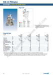
Certified according to DIN ISO 9001 User’s Manual WT-WI02 & Easy Control 2.15 Index INDEX 1 GENERAL INFORMATION ................................................................................................ 5 1.1 1.2 1.2.1 1.2.2 1.3 1.3.1 1.3.2 FEATURES............................................................................................................................. 5 SAFETY ................................................................................................................................. 5 General Safety .................................................................................................................... 5 Special requirements for Ex installations ............................................................................ 6 ORDERING CODES AND ACCESSORIES.................................................................................... 6 Ordering Code ..................................................................................................................... 6 Accessories ......................................................................................................................... 6 2 GETTING STARTED .......................................................................................................... 7 2.1 2.2 2.2.1 2.2.2 2.3 2.3.1 2.3.2 UNPACKING ........................................................................................................................... 7 OPERATING ELEMENTS .......................................................................................................... 7 W*02.................................................................................................................................... 7 CON.USB.WT ..................................................................................................................... 8 PIN ASSIGNMENTS ................................................................................................................. 8 W*02.................................................................................................................................... 8 CON.USB.WT ..................................................................................................................... 8 3 INSTALLATION .................................................................................................................. 9 3.1 3.2 3.3 MECHANICAL ......................................................................................................................... 9 ELECTRICAL .......................................................................................................................... 9 EX INSTALLATION................................................................................................................... 9 4 OPERATION ..................................................................................................................... 10 4.1 4.1.1 4.1.2 4.1.3 4.2 4.2.1 4.2.2 4.2.3 4.2.4 4.2.5 4.2.6 4.2.7 NORMAL OPERATION ............................................................................................................ 10 Using the 4-20mA loop only .............................................................................................. 10 Using the 4-20mA loop and the digital output ................................................................... 11 Using the digital output only .............................................................................................. 12 REMOTE CONTROL .............................................................................................................. 12 Installation of Easy Control ............................................................................................... 13 Connecting the WT to the PC ........................................................................................... 13 Reading the input frequency ............................................................................................. 15 Changing the settings ....................................................................................................... 16 Calibration ......................................................................................................................... 18 Linearization ...................................................................................................................... 19 Save Device Configuration................................................................................................ 19 5 SERVICE AND MAINTENANCE ...................................................................................... 21 5.1 5.2 5.3 MAINTENANCE ..................................................................................................................... 21 TROUBLE SHOOTING ............................................................................................................ 21 SERVICE ............................................................................................................................. 21 6 LISTINGS .......................................................................................................................... 22 6.1 6.2 6.3 6.4 6.5 WARRANTY ......................................................................................................................... 22 DECLARATION OF CONFORMITY ............................................................................................ 22 TECHNICAL DATA................................................................................................................. 22 WEEE AND ROHS .............................................................................................................. 23 ADRESSES .......................................................................................................................... 23 3 4 General Information 1 GENERAL INFORMATION 1.1 Features The converters type W*.02 are passive 4-20 mA sensors with carrier-frequency- (WT) or inductive (WI) input stage. In addition to the analogue output the sensor provides a galvanically isolated open collector output, which can be used either as a switch or frequency output. The frequency output is freely scalable for a calibration to the volume flow independent of the type of flow meter. The W*.02 have an interface integrated in the M12 sensor plug. The interface adapter and remote software KEM »EasyControl« allow for programming the operating parameters and to read the input frequency. The output frequency and current can be linearized with up to 10 points. The W*.02 is supplied either with standard settings or adjusted to a specific flow meter. 1.2 Safety 1.2.1 General Safety All statements regarding safety of operation and technical data in this manual will only apply when the unit is operated correctly in accordance with this manual. The data for Ingress Protection (IP 65) will only apply when all connectors are caped properly with the corresponding counterpart with the same or better IP rating. Cable glands must be populated with cables with the specified diameter and closed properly. During operation all openings of the housing must be closed unless otherwise noted in this manual. All connections to the load and to the supply must be made with shielded cables unless otherwise noted in this manual. This unit must be grounded. This unit must be supplied by a safety approved power supply with outputs which comply with Safety Extra Low Voltage (SELV). As a protection against fire in the positive supply a fuse with a current rating not higher than the current carrying capacity of the cable used is required. 5 General Information 1.2.2 Special requirements for Ex installations When used in hazardous area a suitable separation amplifier or zener barriers must be used. When using long cables make sure that the maximum inductances and capacitances for the respective voltage or gas group are not exceeded. 1.3 Ordering Codes and Accessories 1.3.1 Ordering Code Wa.02-bb.c.d Ex-approval Sensor Material Sensor principle if blank = standard version Ex = Ex-approved versions K = for ZHM 02 to 04 an HM series L = for ZHM 05 to 07 and for temperatures up to +150°C R = for ZHM 01, 01/1 and 01/2 SRZ series and LFM 10 S = centre pickup for ZHM series If blank = stainless steel as per DIN 1.4101 I = inductive T = carrier-frequency 1.3.2 Accessories Ordering Code Description CON.USB.WT: USB-adapter for WT.02 with output plug to loop through the analogue and frequency output. In the remote mode the WT.02 can be powered via the USB interface or via an external power supply. EasyControl: Remote software for WINDOWS® XP or VISTA. With WINDOWS® XP SP3 or N.NET framework is required. Connector M12; 5 pin, female; 713 Shielded cable 6 Getting Started 2 GETTING STARTED 2.1 Unpacking Verify that you have received the following items: When you ordered W*02…: W*02….. User’s manual When you ordered CON.USB.WT CON.USB.WT USB-cable CD incl. software and drivers User’s manual 2.2 Operating Elements 2.2.1 W*02 4 Fig. 1: Operating Elements of W*02 1 = Electrical connector 2 = Lock nut 3 = Installation thread 4 = Pickup tip 7 Getting Started 2.2.2 CON.USB.WT 1 1 Fig. 2: Operating Elements of CON.USB.WT 1 = cable to W*02 2 = USB connector 3 = output connector 4 = control LED 2.3 Pin Assignments 2.3.1 W*02 1 +I 4 1 5 3 Digital Ground 3 2 2 -I 4 WT Frequency Out 5 WT Communication In 2.3.2 CON.USB.WT 1 +I 4 1 5 2 2 -I 3 Digital Ground 3 4 Frequency Out 5 WT supply/n.c. (see chapter 4.2.2) 8 Installation 3 INSTALLATION 3.1 Mechanical Screw the W*02 manually (without tools) into the pickup thread of the flow sensor until you reach the stop. Turn the W*02 back by 90° Fix the lock nut. WARNING Screwing in the W*02 with too much force can damage the pickup tip! 3.2 Electrical Make sure that the flow meter is grounded. NOTE The housing of the W*02 is connected to the shield of the cable. In bigger systems a separate grounding of the meter might be required for avoiding high currents in the cable shield. In that case the shield might be left open or grounded via a capacitance of e. g. 100nF to avoid ground loops. WARNING Inproper grounding and shielding may lead to bad EMC behaviour or danger to your health! Connect the W*02 via a shielded cable to the control unit. The W*02 is specified for a supply voltage of 15 V or 24 V and will operate at supply voltages from 12 V up to 30 V. NOTE Make sure that all cable and wires are connected and fixed properly before applying power to the W*02 For the electrical connections refer to the drawings in chapter 4.1 3.3 Ex Installation The W*02-Ex is intrinsically save when operated with zener barriers. Mount the W*02 as described in chapter 3.1. Connect the W*02 to suitable zener barriers. WARNING When used in hazardous areas the W*02 must not be connected to any circuitry except suitable zener barriers. 9 Operation 4 OPERATION 4.1 Normal operation The W*02 is ready to use and does not require any special settings. If changes of the K factor for the analogue output or of the operational mode are required, please refer to chapter 4.2.4. 4.1.1 Using the 4-20mA loop only The W*02 operates as a passive 4 – 20mA sensor with 2 wire connection. Connect the W*02 according to the figure below. 1 24 V (12...50 V) Imp. in 2 4 5 3 0V WT Fig. 3: Electrical connections, 4-20mA only NOTE For this mode of operation the analogue mode must be set to “Input Frequency”. This is the default setting. The frequency mode can be set to “OFF”. 10 Operation 4.1.2 Using the 4-20mA loop and the digital output In this mode the W*02 operates as a passive 4 – 20mA sensor with auxiliary optically isolated open collector output. Connect the W*02 according to the figure below. 1 24 V Imp. in 2 4 5 3 0V WT Fig. 4: Electrical connections 4-20 mA and digital output The following modes are possible for the digital output: Input Frequency: The input signal is transformed to a square signal and fed to the digital output (pin 4). Switch Normally open: The output is high (open ) at low frequencies. As the input frequency reaches fth + fhysteresis the transistor becomes conducting and the output goes low. As soon as the input frequency drops below fth – fhysteresis the output becomes non conducting again and goes high, provided that an external pull up is connected. Switch Normally closed: The output is low (conducting ) at low frequencies. As the input frequency reaches fth + fhysteresis the transistor becomes non conducting and goes high, provided that an external pull up is connected. As soon as the input frequency drops below fth – fhysteresis the output becomes conducting again and the output goes low. For changing the mode refer to chapter 4.2.4. 11 Operation 4.1.3 Using the digital output only If only a digital output is required, connect the W*02 according to the figure below. For the description of the digital output modes refer to chapter 4.2.4. For best performance and lowest power requirements, the analogue mode can be set to “4 mA”. In that mode the W*02 draws a supply current of 4 mA independent of the input frequency. 1 24 V Imp. in 2 4 5 3 0V WT Fig. 5: Electrical connections digital output only 4.2 Remote Control The W*02 has a built in interface which uses the frequency output and pin 5 of the connector for communication. Communication with a computer is easily implemented by using the USB converter CON.USB.WT and the remote SW KEM EasyControl. NOTE In remote mode the digital output is used for communication and does not provide the frequency output or switch functionality! 12 Operation 4.2.1 Installation of Easy Control NOTE To install EasyControl on the computer administrator rights are required. Start “setup.exe” on the CD. The installation will be performed automatically and an icon for starting EasyControl will be created on your desktop. NOTE If necessary (Windows® XP without SP3) the Microsoft .NET Framework runtime library will be installed on the computer Start “CDM 2.04.06.exe” on the CD and the driver for the CON.USB.WT will be installed. 4.2.2 Connecting the WT to the PC The CON.USB.WT provides 3 modes of operation: POW int: The WT is powered from the USB interface. No connection at the output connector of the CON.USB.WT is required. The frequency output cannot be used. The LED lights up when the CON.USB.WT is connected to a PC. This mode is used for setting up the WT or for simple measurements of the input frequency POW DAM: The WT is powered from the USB interface. Between Pin 2 and 5 of the output connector of the CON.USB.WT a DAM must be connected. This DAM shows the 4 – 20mA signal of the WT. The frequency output cannot be used. The LED lights up when the CON.USB.WT is connected to a PC. This mode is used for setting up the WT, for calibrating the analogue output and for simple measurements of the input frequency POW off: The WT is not powered from the USB interface. An external power supply at the output connector of the CON.USB.WT is required. The LED does not light up. This mode is used for in line monitoring the WT in a complete installation. To set the mode proceed as follows: • Open the CON.USB.WT by removing the 2 screws in the top cover • Set the rotary switch with a small screwdriver to the desired position (see figure 6) • Close the CON.USB.WT with the 2 screws Fig. 6: CON. USB.WT Switch position Connect the CON.USB.WT via the provided USB cable to your PC 13 Operation NOTE Pin 3 of the output connector of the CON.USB.WT is connected to the ground potential of the PC! Connect the cable of the CON.USB.WT to the WT. NOTE When you connect for the first time a CON.USB.WT to your PC, you need administrator rights on the PC as the drivers must be installed on the PC! If necessary connect the DAM or the power supply / control unit to the output of the CON.USB.WT Start EasyControl by double clicking on the icon. Click button “SEARCH DEVICES”. The list of all available KEM CON.USB serial numbers will be shown in the window below the button. The respective serial number you will find on the CON.USB. Select one serial number and confirm with “CONNECT”. The main menu now shows device name, serial number and SW version of the WT and EasyControl is ready to be used. 14 Operation For ending the remote control of the WT click menue item “DEVICE”, “Disconnect”. For finishing EasyControl click “EXIT”. 4.2.3 Reading the input frequency During normal operation it is possible to read the input frequency without disturbing the analogue 4 – 20mA signal. In the main menu a single frequency measurement can be performed by clicking „Single measurement”. In the menu “Continuous measuring” the actual input frequency is displayed continuously with 1 measurement per second. The frequency over time can be displayed as a graph: Set the 4 parameter for the graph and start the measurement by clicking “graph”. When the graph is finished, the total set of values can be stored in a file: Click “store”. If required, name and location of the file can be set individually. 15 Operation 4.2.4 Changing the settings K-Factor “K-Factor” In “Flow. Dim” mass units for mass flow volume units for volume flow “CutOff” cut-off-frequency Setup 16 Operation • Input “Density” “Filter time(0.1-99.9s)” Density of medium must be specified for calculating mass flow Response time of flow output filter • Analogue Output Analogue Output Mode “4mA” The W*02 draws no additional parameters “Flow” “Flow for 20mA” The input frequency is converted in 4-20mA the flow accorded to 20mA • Digital Output Frequency output mode Additional Off Parameter values Description none none digital output is off Input Frequency none none output frequency equals input frequency Switch Switch frequency 1Hz … 5kHz parameters Switch hysteresis Switch mode Flow Output goes to active mode at switch frequency + 0 … 100% hysteresis and goes back to Closed – normally closed normal mode at switch frequency – hysteresis Open – normally open Full scale flow Full scale frequency Output frequency = 10Hz … 5kHz current flow * Fmax/Full scale flow NOTE In the Setup Mode also the analogue output is disabled. The last value is maintened until the setup is finished. Changes in flow will not alter the current! 17 Operation 4.2.5 Calibration The calibration of the W*02 is protected by a password. Click “Calibrate”. Enter “user” as password and confirm with Ok. For calibrating the 4 mA point click on “Test” in the field “Calibrate 4 mA”. Set the value in the field “Showed value” with the arrows up and down to the measured current. Click “Confirm”. The 20 mA point is calibrated the same way. NOTE Changing the device settings is only possible with the KEM master password. 18 Operation 4.2.6 Linearization In the linearization menu a linearization of the analogue output and the corrected frequency output can be defined. Starting at “frequency 1” up to 10 couples of input frequency and frequency error can be specified. Each couple has to be confirmed by clicking “confirm”. The value “error” is defined as the deviation of the input frequency from the ideal input frequency. NOTE Starting at “frequency 1” the frequency value for each couple must be higher than the value of the previous one. The remaining, non used couples are specified by “0” as frequency value! 4.2.7 Save Device Configuration All parameters and device setting can be stored as a *.csv file. Via the menu item “Data”->”Save” you can store the device settings as a *.csv file. 19 Operation Via the menu item “Data”->”Load” you can load the new settings from the formatted *csv file. With button “Store” the loaded settings will be sent to the device. NOTE Please use text editor for changing data in the *.csv file. Please no commas in the floating point numbers! 20 Service and Maintenance 5 SERVICE AND MAINTENANCE 5.1 Maintenance The W*02 does not require regular maintenance. For best performance, however, we recommend checking the calibration of the analogue output every 5 years, in harsh environments even more frequent. A recalibration can be performed by using the CON.USB.WT plus KEM EasyControl or at KEM. 5.2 Trouble shooting In case the W*02 does not work properly, first check the following items: No output signal All cables properly connected? Î Connect the missing cables W*02 properly mounted? Î Check mounting position and, if necessary, mount the W*02 properly Output frequency too low All cables properly connected? Î Reconnect the loose cables Meter working properly? Î Check and, if necessary, replace the meter Output frequency too high or unstable Most probably EMC problems Shield and ground properly connected? Î Connect shield properly. If necessary, try additional means of grounding and shielding 5.3 Service The W*02 does not contain any user serviceable parts. In case of malfunction, please contact your nearest dealer or directly KEM. For the addresses see chapter 6.5 21 Listings 6 LIS STINGS S 6.1 Wa arranty KEM warrrants materia al and producction for a pe eriod of 18 months m after in nstallation an nd start up, max. 24 months m from delivery d date e. 6.2 De eclaration n of confformity See separrate sheet. 6.3 Te echnical Data Analogue signal Type n: Resolution Supply voltage: Allowable load: Operating modes: Digital outtput Type: Protective e resistor: Frequencyy range Operating modes pecifications Further sp Measuring g frequency e time Response Temperatu ure drift Connectorr: Ambient te emperature: Medium te emperature: ns: Dimension Material: n class: Protection 4–20 mA A, 2-wire (passsive) 5 µA 12–30 V, regulated V) / 20 mA, max. m 800 (UB–12V ON (frequency propo ortional curre ent) pply current 4 mA indepe endent of freq quency) OFF (sup open collector, poten ntial free 1,600 1–3,000 Hz OFF (frequency outp put disabled) equency) 1 : 1 (outtput frequenccy = input fre CORR (sscalable outp put frequency y) SW (swittch output) 1–3,000 Hz uency depen nds on flow meter) m (actually usable frequ Hz) 250ms (ffor input frequencies > 5H < 100 pp pm / K M12, 5-p pin 1 = +I 2 = –I 3 = emittter (digital ground) 4 = collector (frequen ncy output) ote input 5 = remo –20 ... + 50°C 120 °C with a distance off at least 25 mm –20 to +1 be etween flow meter m and ele ectronic housing se ee drawing (sshow K or R version) stainlesss steel IP65 Fig. 7 7: W*02 dimens sions 22 Listings 6.4 WEEE and RoHS The unit described herein is not subject to the WEEE directive and the corresponding national laws. At the end of life forward the unit to a specialised recycling company and do not dispose it of f as domestic waste. The unit described herein fully complies with the RoHS directive. 6.5 Adresses Main office KEM Küppers Elektromechanik GmbH Liebigstraße 2 D-85757 Karlsfeld Germany tel +49 81 31 5 93 91 - 0 [email protected] www.kem-kueppers.com Please see our website for worldwide contacts. 23 ANSPRECHPARTNER WELTWEIT KEM –.Zentrale Liebigstraße 2 D-85757 Karlsfeld T. +49 8131 5 93 91-4 F: +49 8131 9 26 04 [email protected] KEM – Büro West Im Langen Hahn 44 D-58515 Lüdenscheid T. +49 2351 9 78 80 F: +49 2351 9 78 83 1 [email protected] KEM – Büro Süd Dahlienweg 35 D-73765 Neuhausen T. +49 7158 98 56 82 F: +49 7158 98 56 83 [email protected] Dänemark E.Eberhardt ApS Bygstubben 6 DK-2950 Vedbaek T. +45 45 89 33 66 [email protected] Norwegen Flow Treknikk as Olav Brunborgsc. 27, Postboks 244 N-1377 Billingstad T. +47 66 77 54 00 [email protected] Singapur Polyquip Engineering Pte Ltd Blk 20 Woodlands Link # 08-12 SGP-738733 Singapur T. +65 67 53 79 97 [email protected] China KEM China Rm. 2429, JinYuan Office Building No.36 CN-BeiYuan Road, Beijing 100012 T. +86 10 52 00 37 38 [email protected] Polen Newtech Engineering Ul. Sowinskiego 3 PL- 4-100 Gliwice T. +48 32 237 61 98 [email protected] Slowakai Bibus SK, s.r.o. Priemyselná 4 SK-949-01 Nitra T. +421 377 41 25 25 [email protected] Finnland Wexon Oy Juhanilantie 4 FI-01740 Vantaa T. +358 9 29 01 40 [email protected] Portugal Contimetra Departmento Industria R. Braamcamp 88-40 Dt0 P-1269-020 Lisboa T. ++351 213 86 05 00 [email protected] Spanien Ortrat S.L. Calle La Sofora 13+15 ES-28020 Madrid T. +349 1 57 91 60 6 [email protected] Großbritannien KEM Küppers UK 2 Highfield Drive, Ickenham Uxbridge UB10 8AL England T. +44 1895 23 35 52 [email protected] Russland Michael Dueck Industrievertretungen und Vertrieb St-Vither-Str. 12 D-50171 Kerpen T. +49 2237 67 91 88 [email protected] Taiwan Yuden Electric Co.,Ltd. Taiwan Headquarter 5F, No. 121, Li De ST, JHONGHE TAIPEI COUNTY 235, Taiwan ROC T. +886 2 82 21 29 58 [email protected] Hong Kong Asia Technology and Instrument Ltd. Unit 5, 9/F., Free Trade Centre 49 Tsun Yip Street, Kwun Tong HK-Kowloon T. +85 227 16 55 56 [email protected] Schweden Petronic AB SE-590 93 Gunnebobruk T. +46 490 25 85 00 [email protected] USA AW-LAKE Company Electronics for Instrumentation 8809 Industrial Dr. Franksville , WI 53126, USA T. +1 262 88 49 80 0 sales@aw-lake-com Italien Ingg. Vigo e Cova SAS Piazzale Segrino 6/a# I-20159 Milano T. +39 02 668 82 02 [email protected] www.kem-kueppers.com [email protected] KEM Küppers Elektromechanik GmbH I Liebigsraße 2 I D-85757 Karlsfeld I tel +49 8131 5 93 91 - 0 I fax +49 8131 9 26 04 Copyright KEM, Änderungen vorbehalten, ES. Rev 001- 05/03/10