1
Agilent 75000 Series B
Agilent E1330A/E1330B
Quad 8-Bit Digital Input/Output
Modules
Service Manual
Enclosed is the Service Manual for the Agilent E1330A/E1330B
Quad 8-Bit Digital Input/Output Modules. Insert this manual,
along with any other VXIbus manuals that you have, into the
binder that came with your Agilent Technologies mainframe.
*E1330-90012*
Manual Part Number: E1330-90012
Printed in Malaysia E
Certification
Agilent Technologies certifies that this product met its published specifications at the time of shipment from the factory. Agilent
Technologies further certifies that its calibration measurements are traceable to the United States National Institute of Standards and
Technology (formerly National Bureau of Standards), to the extent allowed by that organization’s calibration facility, and to the calibration
facilities of other International Standards Organization members.
Warranty
This Agilent Technologies product is warranted against defects in materials and workmanship for a period of one (1) year from date of
shipment. Duration and conditions of warranty for this product may be superseded when the product is integrated into (becomes a part
of) other Agilent products. During the warranty period, Agilent Technologies will, at its option, either repair or replace products which
prove to be defective.
For warranty service or repair, this product must be returned to a service facility designated by Agilent Technologies. Buyer shall prepay
shipping charges to Agilent and Agilent shall pay shipping charges to return the product to Buyer. However, Buyer shall pay all shipping
charges, duties, and taxes for products returned to Agilent from another country.
Agilent warrants that its software and firmware designated by Agilent for use with a product will execute its programming instructions
when properly installed on that product. Agilent does not warrant that the operation of the product, or software, or firmware will be
uninterrupted or error free.
Limitation Of Warranty
The foregoing warranty shall not apply to defects resulting from improper or inadequate maintenance by Buyer, Buyer-supplied products
or interfacing, unauthorized modification or misuse, operation outside of the environmental specifications for the product, or improper site
preparation or maintenance.
The design and implementation of any circuit on this product is the sole responsibility of the Buyer. Agilent does not warrant the Buyer’s
circuitry or malfunctions of Agilent products that result from the Buyer’s circuitry. In addition, Agilent does not warrant any damage that
occurs as a result of the Buyer’s circuit or any defects that result from Buyer-supplied products.
NO OTHER WARRANTY IS EXPRESSED OR IMPLIED. Agilent SPECIFICALLY DISCLAIMS THE IMPLIED WARRANTIES
OF MERCHANTABILITY AND FITNESS FOR A PARTICULAR PURPOSE.
Exclusive Remedies
THE REMEDIES PROVIDED HEREIN ARE BUYER’S SOLE AND EXCLUSIVE REMEDIES. Agilent SHALL NOT BE LIABLE
FOR ANY DIRECT, INDIRECT, SPECIAL, INCIDENTAL, OR CONSEQUENTIAL DAMAGES, WHETHER BASED ON CONTRACT, TORT, OR ANY OTHER LEGAL THEORY.
Notice
The information contained in this document is subject to change without notice. Agilent Technologies MAKES NO WARRANTY OF
ANY KIND WITH REGARD TO THIS MATERIAL, INCLUDING, BUT NOT LIMITED TO, THE IMPLIED WARRANTIES OF
MERCHANTABILITY AND FITNESS FOR A PARTICULAR PURPOSE. Agilent shall not be liable for errors contained herein or for
incidental or consequential damages in connection with the furnishing, performance or use of this material. This document contains
proprietary information which is protected by copyright. All rights are reserved. No part of this document may be photocopied, reproduced,
or translated to another language without the prior written consent of Agilent Technologies, Inc. Agilent assumes no responsibility for the
use or reliability of its software on equipment that is not furnished by Agilent.
U.S. Government Restricted Rights
The Software and Documentation have been developed entirely at private expense. They are delivered and licensed as "commercial
computer software" as defined in DFARS 252.227- 7013 (Oct 1988), DFARS 252.211-7015 (May 1991) or DFARS 252.227-7014 (Jun
1995), as a "commercial item" as defined in FAR 2.101(a), or as "Restricted computer software" as defined in FAR 52.227-19 (Jun 1987)(or
any equivalent agency regulation or contract clause), whichever is applicable. You have only those rights provided for such Software and
Documentation by the applicable FAR or DFARS clause or the Agilent standard software agreement for the product involved.
Agilent E1330A/E1330B Quad 8-Bit Digital Input/Output Modules Service Manual
Edition 3 Rev Copyright © 1996-2006 Agilent Technologies, Inc. All Rights Reserved.
i
Printing History
The Printing History shown below lists all Editions and Updates of this manual and the printing date(s). The first printing of the manual
is Edition 1. The Edition number increments by 1 whenever the manual is revised. Updates, which are issued between Editions, contain
replacement pages to correct the current Edition of the manual. Updates are numbered sequentially starting with Update 1. When a new
Edition is created, it contains all the Update information for the previous Edition. Each new Edition or Update also includes a revised copy
of this printing history page. Many product updates or revisions do not require manual changes and, conversely, manual corrections may
be done without accompanying product changes. Therefore, do not expect a one-to-one correspondence between product updates and
manual updates.
Edition 1 (Part Number E1330-90010). . . . . . . . . . . . . . . . . . . . December 1992
Edition 2 (Part Number E1330-90011). . . . . . . . . . . . . . . . . . . . November 1994
Edition 3 (Part Number E1330-90012). . . . . . . . . . . . . . . . . . . . . . . . April 1996
Edition 3 Rev 2 (Part Number E1330-90012) . . . . . . . . . . . . . . . . . . . June 2006
%DITION2EV0ART.UMBER%3EPTEMBER
Safety Symbols
Instruction manual symbol affixed to product.
Indicates that the user must refer to the manual for specific WARNING or CAUTION
information to avoid personal injury or damage to the product.
Alternating current (AC).
Direct current (DC).
Indicates hazardous voltages.
Indicates the field wiring terminal that must
be connected to earth ground before operating
the equipment—protects against electrical
shock in case of fault.
or
WARNING
Frame or chassis ground terminal—typically
connects to the equipment’s metal frame.
CAUTION
Calls attention to a procedure, practice, or condition that could cause bodily injury or death.
Calls attention to a procedure, practice, or condition that could possibly cause damage to
equipment or permanent loss of data.
WARNINGS
The following general safety precautions must be observed during all phases of operation, service, and repair of this product.
Failure to comply with these precautions or with specific warnings elsewhere in this manual violates safety standards of design,
manufacture, and intended use of the product. Agilent Technologies assumes no liability for the customer’s failure to comply with
these requirements.
Ground the equipment: For Safety Class 1 equipment (equipment having a protective earth terminal), an uninterruptible safety earth
ground must be provided from the mains power source to the product input wiring terminals or supplied power cable.
DO NOT operate the product in an explosive atmosphere or in the presence of flammable gases or fumes.
For continued protection against fire, replace the line fuse(s) only with fuse(s) of the same voltage and current rating and type.
DO NOT use repaired fuses or short-circuited fuse holders.
Keep away from live circuits: Operating personnel must not remove equipment covers or shields. Procedures involving the removal of
covers or shields are for use by service-trained personnel only. Under certain conditions, dangerous voltages may exist even with the
equipment switched off. To avoid dangerous electrical shock, DO NOT perform procedures involving cover or shield removal unless you
are qualified to do so.
DO NOT operate damaged equipment: Whenever it is possible that the safety protection features built into this product have been
impaired, either through physical damage, excessive moisture, or any other reason, REMOVE POWER and do not use the product until
safe operation can be verified by service-trained personnel. If necessary, return the product to an Agilent Technologies Sales and Service
Office for service and repair to ensure that safety features are maintained.
DO NOT service or adjust alone: Do not attempt internal service or adjustment unless another person, capable of rendering first aid and
resuscitation, is present.
DO NOT substitute parts or modify equipment: Because of the danger of introducing additional hazards, do not install substitute parts
or perform any unauthorized modification to the product. Return the product to an Agilent Technologies Sales and Service Office for
service and repair to ensure that safety features are maintained.
ii
Declaration of Conformity
Declarations of Conformity for this product and for other Agilent products may be downloaded from the Internet. There are two methods to obtain
the Declaration of Conformity:
•
Go to http://regulations.corporate.agilent.com/DoC/search.htm . You can then search by product number to find the latest Declaration
of Conformity.
• Alternately, you can go to the product web page (www.agilent.com/find/E1330B), click on the Document Library tab then
scroll down until you find the Declaration of Conformity link.
Agilent 75000 Series B Service Documentation
Suggested Sequence to Use Manuals
Manual Descriptions
Installation and Getting Started Guide. This manual contains step-by-step instructions for all aspects of
plug-in module and mainframe installation. Introductory programming information and examples are also
included.
Mainframe User’s Manual. This manual contains programming information for the mainframe, front panel
operation information (for the Agilent E1301B mainframe), and general programming information for
instruments installed in the mainframe.
Plug-In Module User’s Manuals. These manuals contain plug-in module programming and configuration
information. Each manual contains examples for the most-used module functions, and a complete SCPI
command reference for the plug-in module.
Mainframe Service Manual. This manual contains service information for the mainframe. It contains
information for ordering replaceable parts and exchanging assemblies. Information and procedures for
performance verification, adjustment, preventive maintenance, troubleshooting, and repair are also included.
Plug-In Module Service Manuals. These manuals contain plug-in module service information. Each manual
contains information for exchanging the module and/or ordering replaceable parts. Depending on the module,
information and procedures for functional verification, operation verification, performance verification,
adjustment, preventive maintenance, troubleshooting, and repair are also provided.
iv
What’s in this Manual
Manual Overview
This manual shows how to service the Agilent E1330A/B Quad 8-Bit Digital I/O Module. Consult the Agilent
E1330A/B User’s Manual for additional information on installing, configuring, and operating the Agilent
E1330A/B. Consult the appropriate mainframe user’s manual for information on configuring and operating the
mainframe.
Manual Content
Chapter
Title
Content
1
General
Information
Provides a basic description and lists the test equipment required for service.
2
Verification
Tests
Functional verification, operation verification, and performance verification tests.
3
Replaceable
Parts
Lists replaceable parts for the module.
4
Service
Procedures to aid in fault isolation and repair of the module.
v
vi
Table of Contents - Agilent E1330A/B Service Manual
Chapter 1 — Introduction
Introduction . . . . . . . . . . . . . . . . . . . . . . . . . . . . . . . . . . . . . . . 1-1
Safety Considerations . . . . . . . . . . . . . . . . . . . . . . . . . . . . . . . . . . 1-2
Warnings . . . . . . . . . . . . . . . . . . . . . . . . . . . . . . . . . . . . . . 1-2
Cautions . . . . . . . . . . . . . . . . . . . . . . . . . . . . . . . . . . . . . . . 1-3
Digital I/O Description . . . . . . . .
Agilent E1330A/B Description . .
Digital I/O Module Specifications .
Digital I/O Module Environment .
Digital I/O Module Serial Numbers
Digital I/O Module Options . . . .
.
.
.
.
.
.
.
.
.
.
.
.
.
.
.
.
.
.
.
.
.
.
.
.
.
.
.
.
.
.
.
.
.
.
.
.
.
.
.
.
.
.
.
.
.
.
.
.
.
.
.
.
.
.
.
.
.
.
.
.
.
.
.
.
.
.
.
.
.
.
.
.
.
.
.
.
.
.
.
.
.
.
.
.
.
.
.
.
.
.
.
.
.
.
.
.
.
.
.
.
.
.
.
.
.
.
.
.
.
.
.
.
.
.
.
.
.
.
.
.
.
.
.
.
.
.
.
.
.
.
.
.
.
.
.
.
.
.
.
.
.
.
.
.
.
.
.
.
.
.
1-4
1-4
1-4
1-4
1-5
1-5
Recommended Test Equipment . . . . . . . . . . . . . . . . . . . . . . . . . . . . . 1-6
Inspection/ Shipping . . . . . . . . . . . . . . . . . . . . . . . . . . . . . . . . . . . 1-6
Initial Inspection . . . . . . . . . . . . . . . . . . . . . . . . . . . . . . . . . . . 1-6
Shipping Guidelines . . . . . . . . . . . . . . . . . . . . . . . . . . . . . . . . . 1-8
Chapter 2 — Verification Tests
Introduction . . . . . . . . . .
Test Conditions/Procedures
Performance Test Record .
Verification Test Examples
.
.
.
.
.
.
.
.
.
.
.
.
.
.
.
.
.
.
.
.
.
.
.
.
.
.
.
.
.
.
.
.
.
.
.
.
.
.
.
.
.
.
.
.
.
.
.
.
.
.
.
.
.
.
.
.
.
.
.
.
.
.
.
.
.
.
.
.
.
.
.
.
.
.
.
.
.
.
.
.
.
.
.
.
.
.
.
.
.
.
.
.
.
.
.
.
.
.
.
.
.
.
.
.
.
.
.
.
.
.
.
.
.
.
.
.
2-1
2-1
2-1
2-1
Functional Verification Test . . . . . . . . . . . . . . . . . . . . . . . . . . . . . . . 2-2
Procedure . . . . . . . . . . . . . . . . . . . . . . . . . . . . . . . . . . . . . . 2-2
Operation Verification Test . . . . . . . . . . . . . . . . . . . . . . . . . . . . . . . 2-2
Performance Verification Tests . . . . . . . . . . . . . . . . . . . . . . . . . . . . . 2-3
Test Cable . . . . . . . . . . . . . . . . . . . . . . . . . . . . . . . . . . . . . . 2-3
Test 2-1: Digital Test . . . . . . . . . . . . . . . . . . . . . . . . . . . . . . . . 2-3
Performance Test Record . . .
Test Limits . . . . . . . . .
Measurement Uncertainty .
Test Accuracy Ratio (TAR)
.
.
.
.
.
.
.
.
.
.
.
.
.
.
.
.
.
.
.
.
.
.
.
.
.
.
.
.
.
.
.
.
.
.
.
.
.
.
.
.
.
.
.
.
.
.
.
.
.
.
.
.
.
.
.
.
.
.
.
.
.
.
.
.
.
.
.
.
.
.
.
.
.
.
.
.
.
.
.
.
.
.
.
.
.
.
.
.
.
.
.
.
.
.
.
.
.
.
.
.
.
.
.
.
.
.
.
.
.
.
.
.
.
.
.
.
2-8
2-8
2-8
2-8
Chapter 3 — Replaceable Parts
Introduction . . . . . . . . . . . . . . . . . . . . . . . . . . . . . . . . . . . . . . . 3-1
Replaceable Parts List . . . . . . . . . . . . . . . . . . . . . . . . . . . . . . . . . . 3-1
Mechanical Parts Locator . . . . . . . . . . . . . . . . . . . . . . . . . . . . . . . . 3-5
Chapter 4 — Service
Introduction . . . . . . . . . . . .
Equipment Required . . . . . .
Service Aids . . . . . . . . . .
Digital I/O Module Description
.
.
.
.
.
.
.
.
.
.
.
.
.
.
.
.
.
.
.
.
.
.
.
.
.
.
.
.
.
.
.
.
.
.
.
.
.
.
.
.
.
.
.
.
.
.
.
.
.
.
.
.
.
.
.
.
.
.
.
.
.
.
.
.
.
.
.
.
.
.
.
.
.
.
.
.
.
.
.
.
.
.
.
.
.
.
.
.
.
.
.
.
.
.
.
.
.
.
.
.
.
.
.
.
.
.
.
.
4-1
4-1
4-1
4-1
Repair Strategy . . . . . . . . . . . . . . . . . . . . . . . . . . . . . . . . . . . . . 4-2
Troubleshooting Techniques
Identifying the Problem .
Making Visual Checks . .
Testing the Module . . .
.
.
.
.
.
.
.
.
.
.
.
.
.
.
.
.
.
.
.
.
.
.
.
.
.
.
.
.
.
.
.
.
.
.
.
.
.
.
.
.
.
.
.
.
.
.
.
.
.
.
.
.
.
.
.
.
.
.
.
.
.
.
.
.
.
.
.
.
.
.
.
.
.
.
.
.
.
.
.
.
.
.
.
.
.
.
.
.
.
.
.
.
.
.
.
.
.
.
.
.
.
.
.
.
.
.
.
.
.
.
.
.
.
.
.
.
.
.
.
.
4-2
4-2
4-2
4-3
Repair and Maintenance Guidelines .
ESD Precautions . . . . . . . . .
Soldering Printed Circuit Boards
Post-Repair Safety Checks . . . .
.
.
.
.
.
.
.
.
.
.
.
.
.
.
.
.
.
.
.
.
.
.
.
.
.
.
.
.
.
.
.
.
.
.
.
.
.
.
.
.
.
.
.
.
.
.
.
.
.
.
.
.
.
.
.
.
.
.
.
.
.
.
.
.
.
.
.
.
.
.
.
.
.
.
.
.
.
.
.
.
.
.
.
.
.
.
.
.
.
.
.
.
.
.
.
.
.
.
.
.
.
.
.
.
4-4
4-4
4-4
4-4
Appendix A — Verification Tests - C Programs
Funcitonal Verification Test . . . . . . . . . . . . . . . . . . . . . . . . . . . . . . . A-1
Performance Verification Test . . . . . . . . . . . . . . . . . . . . . . . . . . . . . . A-2
1
General Information
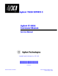
Introduction
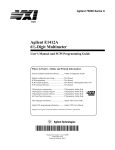
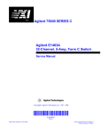
This manual contains information required to test, troubleshoot, and repair
the Agilent E1330A/B Quad 8-Bit Digital I/O Module. See the Agilent
E1330A/B User’s Manual for additional information on the Agilent
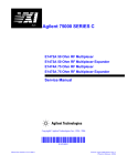
E1330A/B. Figure 1-1 shows the Agilent E1330A/B Quad 8-Bit Digital I/O
Module.
Figure 1-1. Agilent E1330A/B Digital I/O Module
General Information 1-1
Safety
Considerations
This product is a Safety Class I instrument that is provided with a protective
earth terminal when installed in the mainframe. Check the mainframe,
Digital I/O Module, and all related documentation for safety markings and
instructions before operation or service.
Refer to the WARNINGS page (page iii) in this manual for a summary of
safety information. Safety information for preventive maintenance, testing,
and service follows and is also found throughout this manual.
Warnings
WARNING
This section contains WARNINGS which must be followed for your
protection when performing equipment maintenance or repair.
SERVICE-TRAINED PERSONNEL ONLY. The information in this
manual is for service-trained personnel who are familiar with
electronic circuitry and are aware of the hazards involved. To
avoid personal injury or damage to the instrument, do not
perform procedures in this manual or do any servicing unless
you are qualified to do so.
CHECK MAINFRAME POWER SETTINGS. Before applying
power, verify that the mainframe setting matches the line
voltage and that the correct fuse is installed. An uninterruptible
safety earth ground must be provided from the main power
source to the supplied power cord set.
GROUNDING REQUIREMENTS. Interruption of the protective
(grounding) conductor (inside or outside the mainframe) or
disconnecting the protective earth terminal will cause a
potential shock hazard that could result in personal injury.
(Grounding one conductor of a two-conductor outlet is not
sufficient protection.)
IMPAIRED PROTECTION. Whenever it is likely that instrument
protection has been impaired, the mainframe must be made
inoperative and be secured against any unintended operation.
REMOVE POWER IF POSSIBLE. Some procedures in this
manual may be performed with power supplied to the
mainframe while protective covers are removed. Energy
available at many points may, if contacted, result in personal
injury. (If maintenance can be performed without power
applied, the power should be removed.)
1-2 General Information
WARNING
USING AUTOTRANSFORMERS. If the mainframe is to be
energized via an autotransformer (for voltage reduction) make
sure the common terminal is connected to neutral (that is, the
grounded side of the main’s supply).
CAPACITOR VOLTAGES. Capacitors inside the mainframe may
remain charged even when the mainframe has been
disconnected from its source of supply.
USE PROPER FUSES. For continued protection against fire
hazard, replace the line fuses only with fuses of the same
current rating and type (such as normal blow, time delay, etc.).
Do not use repaired fuses or short-circuited fuseholders.
Cautions
CAUTION
This section contains CAUTIONS which must be followed to avoid damage
to the equipment when performing instrument maintenance or repair.
MAXIMUM VOLTAGE/CURRENT. The maximum voltage that may
be applied between any connector pin and any other point, shield, or
chassis is 5 VPeak.
STATIC ELECTRICITY. Static electricity is a major cause of
component failure. To prevent damage to the electrical components in
the Digital I/O module, observe anti-static techniques whenever
working on a Digital I/O module.
General Information 1-3
Digital I/O
Description
NOTE
Agilent E1330A/B
Description
The Agilent E1330A/B Digital I/O Module is an "instrument" in a VXIbus
mainframe. As such, each Digital I/O module is assigned an error queue,
input and output buffers, and a status register.
Instruments are based on the logical addresses of the plug-in modules. See
the Agilent 75000 Series B Installation and Getting Started Guide to set the
addresses to create an instrument.
The Agilent E1330A/B provides four independent 8-bit digital I/O ports
compatible with TTL logic levels. Each port can be software configured for
operation as input or output with either positive or negative true logic. The
ports can be combined to provide 16 bit (WORD) or 32 bit (LWORD)
operations. In addition to the eight digital data lines, six handshake lines are
included per port. The handshake lines can also be combined (via jumpers
on the component assembly) to provide proper handshaking for combined
ports. The data lines of each port are provided with a jumpered pull-up for
dry contact closure sensing. User connections to the Digital I/O module are
made through two 60-pin connectors on the rear panel.
The Agilent E1330B added SCPI command capabilities related to LWORD
and Block operations. The procedures in this manual work equally well
with either an Agilent E1330A or Agilent E1330B.
Digital I/O Module
Specifications
See Appendix A of the Agilent E1330A/B User’s Manual for Agilent
E1330A/B specifications. These specifications are the performance
standards or limits against which the instrument may be tested.
Digital I/O Module
Environment
The recommended operating environment for the Agilent E1330A/B Digital
I/O module is:
Environment
1-4 General Information
Temperature
Humidity
Operating
0oC to +55oC
<65% relative (0oC to +40oC)
Storage and
Shipment
-40oC to +75oC
<65% relative (0oC to +40oC)
Digital I/O Module
Serial Numbers
Digital I/O modules covered by this manual are identified by a serial
number prefix listed on the title page. Agilent Technologies uses a two-part
serial number in the form XXXXAYYYYY, where XXXX is the serial
prefix, A is the country of origin (A=USA), and YYYYY is the serial suffix.
The serial number prefix identifies a series of identical instruments. The
serial number suffix is assigned sequentially to each instrument.
The serial number plate is located on the backplane connector. If the serial
number prefix of your instrument is greater than the one listed on the title
page, a Manual Update (as required) will explain how to adapt this manual
to your instrument.
Digital I/O Module
Options
There are no electrical or mechanical options available for the Agilent
E1330A/B Digital I/O Modules.
General Information 1-5
Recommended
Test Equipment
Table 1-1 lists the test equipment recommended for testing, adjusting, and
servicing the Digital I/O modules. Essential requirements for each piece of
test equipment are described in the Requirements column.
Table 1-1. Recommended Test Equipment
Instrument
Requirements
Recommended
Model
Use*
Controller, GPIB
GPIB compatibility as defined by IEEE
Standard 488-1987 and the identical
ANSI Standard MC1.1: SH1, AH1, T2,
TE0, L2, LE0, SR0, RL0, PP0, DC0,
DT0, and C1, 2, 3, 4, 5.
HP 9000 Series 300
or
IBM compatible PC with
BASIC
F,O,
P,T
Mainframe
Compatible with Digital I/O Module
Agilent E1300A,
E1301A, E13002A or
E1401B/T, E1421A
(requires E1405A/B)
F,O,
P,T
Test Cable
Connects handshake and data lines
from Port 0 to Port 2 and from Port 1 to
Port 3.
Agilent E1330-61603
O,P
* F = Functional Verification Tests, O = Operation Verification Tests, P = Performance Verification Tests, T = Troubleshooting
Inspection/
Shipping
Initial
Inspection
WARNING
1-6 General Information
This section contains initial (incoming) inspection and shipping guidelines
for the Digital I/O module.
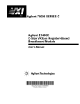
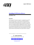
Use the steps in Figure 1-2 as guidelines to perform initial inspection of a
Digital I/O module. Performance Verification tests are optional.
To avoid possible hazardous electrical shock, do not perform
electrical tests if there are signs of shipping damage to the
shipping container or to the instrument.
Notify Agilent and carrier.
Notify Agilent
Figure 1-2. Initial (Incoming) Inspection Guidelines
General Information 1-7
Shipping
Guidelines
Follow the steps in Figure 1-3 to return a Digital I/O module to an Agilent
Technologies Sales and Support Office or Service Center.
1 Prepare the Digital I/O module
• Remove user wiring from the module
• Attach tag to module/pod that identifies
- Owner
- Model Number/Serial Number
- Service Required
• Place tagged device in approved anti-static bag
2 Package the Digital I/O module
• Place packaged Digital I/O module in shipping
carton*
• Place 75 to 100 mm (3 to 4 inches) of shockabsorbing material around the Digital I/O module
• Seal the shipping carton securely
• Mark the shipping carton FRAGILE
3 Ship the Digital I/O module to Agilent Technologies
• Place address label on shipping carton
• Send carton to Agilent Technologies
Figure 1-3. Packaging/Shipping Guidelines
* We recommend that you use the same shipping materials as those used in factory packaging (available from Agilent Technologies).
For other (commercially-available) shipping materials, use a double wall-carton with minimum 2.4 MPa (350 psi) test.
1-8 General Information
2
Verification Tests
Introduction
This chapter describes the verification tests for the Agilent E1330A/B
modules. The three levels of test procedures described in this chapter are
used to verify that the Agilent E1330A/B:
• is functional (Functional Verification Test)
• meets selected testable specifications (Operation Verification)
• meets all testable specifications (Performance Verification)
Test Conditions/
Procedures
See Table 1-1 for test equipment requirements. You should complete the
Performance Verification tests at least once a year. For heavy use or severe
operating environments, perform the tests more often. The verification tests
assume that the person performing the tests understands how to operate the
mainframe, the module, and the specified test equipment. The test
procedures do not specify equipment settings for test equipment except in
general terms. It is assumed that a qualified, service-trained technician will
select and connect the cables, adapters, and probes required for the test.
Performance
Test Record
The results of each Performance Verification test may be recorded in Table
2-1, Performance Test Record, at the end of this chapter. You can make a
copy of this form, if desired.
Verification Test
Examples
Each verification test procedure includes an example program that performs
the test. All example programs assume the following configuration:
• HP 9000 Series 200/300 computer
• BASIC programming language
• Module address 70918
Verification Tests 2-1
Functional
Verification
Test
Procedure
The Functional Verification Test for the Agilent E1330A/B modules
consists of sending the *IDN? command and checking the response. This
test can be used to verify that the module is connected properly and is
responding to a basic command.
1. Verify that the module is properly installed in mainframe
2. Verify that the mainframe has passed its power-on test.
3. Send *IDN? to the module (see example following)
4. The return should be as follows (revision number may vary):
HEWLETT-PACKARD,E1330A,0,A.06.00
NOTES
If the primary address setting, secondary address setting, or the interface
select code is set incorrectly, the module will not respond. Verify proper
address selection before troubleshooting.
Both the Agilent E1330A and Agilent E1330B return the string shown in
Step 4. The E1330B will return "E1330A" in response to the *IDN? query.
Example
An example follows which uses an HP 9000 Series 300 computer with
BASIC and a module address of 70918.
10 DIM A$[100]
20 OUTPUT 70918;"*IDN?"
Send the ID command
30 ENTER 70918;A$
Get response
40 PRINT A$
50 END
Operation
Verification
Test
The procedures in this section are used to provide a high level of confidence
that the module is meeting published specifications. The Operation
Verification test is a subset of the Performance Verification tests and is
suitable for checkout after performing repairs.
The Operation Verification Test is performed by completing the Digital Test
(Test 2-1) as described in the Performance Verification test procedures. This
test is usually sufficient to verify that the module is meeting its
specifications.
2-2 Verification Tests
Performance
Verification
Tests
The procedure in this section is used to test the module’s electrical
performance using the specifications in Appendix A — Specifications of the
Agilent E1330A/B Modules User’s Manual as the performance standard.
The Performance Verification test is a test of each Digital I/O line on each
port and a test of the three main handshake lines for each port. This test is
sufficient to determine that the module is operating within specifications.
This test is suitable for incoming inspection, troubleshooting, and preventive
maintenance.
Test Cable
Test 2-1: Digital
Test
Data Line Test
A test cable is required to run the Performance Verification test. This test
cable is available from Agilent Technologeis (Part Number E1330-61603).
This test verifies that all ports meet the specification for the module.
1. Setup and Install the Digital I/O module
• Remove power from the mainframe. Remove Agilent
E1330A/B from the mainframe (as required).
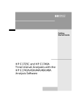
• Record the locations of the Pull-up Enable and any FLG
Combine jumpers on the Agilent E1330A/B.
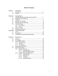
• Set Port 0 and Port 1 Pull-up Enable jumpers to the Enable
position as shown in Figure 2-1.
• Set Port 2 and Port 3 Pull-up Enable jumpers to the Disable
position as shown in Figure 2-1.
• Remove any FLG Combine jumpers installed.
• Install the Agilent E1330A/B in the mainframe.
• Install the Test Cable as shown in Figure 2-2.
• Turn the mainframe power ON.
2. Check Port 0 Write and Port 2 Read
•
•
•
•
•
Send *RST to the module.
Send SOUR:DIG:DATA0 #B00000001 to the module.
Send MEAS:DIG:DATA2? to the module.
Enter the response and compare to the binary data sent.
Repeat this step using the following binary data strings:
"00000010", 00000100", "00001000",
"00010000","00100000","01000000",and "10000000". Use the
command SOUR:DIG:DATA0 #Bssssssss where ssssssss = the
binary data string.
• Enter a Pass or Fail in Table 2-1.
Verification Tests 2-3
Figure 2-1. Jumper Settings
Figure 2-2. Test Cable Installation
2-4 Verification Tests
3. Repeat for Ports 1 through 3
• Repeat step 2 for ports 1, 2, and 3.
• Use SOUR:DIG:DATAn #Bssssssss and MEAS:DIG:DATAn?
where n = port number and ssssssss = the binary string.
• For Port 1 Write, use Port 3 Read. For Port 2 Write, use Port 0
Read. For Port 3 Write, use Port 1 Read.
4. Check Port 0 CTL and Port 2 FLG handshake lines
•
•
•
•
•
•
•
•
•
Send *RST to the module.
Send SOUR:DIG:CONT0 1 to the module.
Send MEAS:DIG:FLAG2? to the module.
Enter the response. The response should be 1.
Enter a Pass or Fail in Table 2-1.
Send SOUR:DIG:CONT0 0 to the module.
Send MEAS:DIG:FLAG2? to the module.
Enter the response. The response should be 0.
Enter a Pass or Fail in Table 2-1.
5. Repeat for Ports 1, 2, and 3
• Repeat step 4 for ports 1, 2, and 3.
• Send SOUR:DIG:CONTn f to the module where n = port
number and f = is a binary toggle (0 and 1).
• Send MEAS:DIG:FLAGn to the module where n = port
number.
• For Port 1 CTL, use Port 3 FLG. For Port 2 CTL, use Port 0
FLG. For Port 3 CTL, use Port 1 FLG.
6. Reset the module jumpers
•
•
•
•
Example: Digital Test
Turn mainframe power OFF.
Remove the Test Cable from the module.
Remove the module from the mainframe.
Reset the module jumpers to the positions recorded in Step 1.
This example performs a bit walk test of all bits on all ports and checks the
module’s ability to set and reset the handshake lines on each port.
10! RE-SAVE "DIO_TEST"
20
DISP CHR$(129)
30
ASSIGN @Dio TO 70918
40
OUTPUT @Dio;"*CLS"
50
Fail = 0
60
DIM A$[255],B$[32],Bit_walk$(7)[8]
70
DATA "00000001","00000010","00000100","00001000",
"00010000","00100000","01000000","10000000"
Verification Tests 2-5
80
READ Bit_walk$(*)
90
CLEAR SCREEN
100 PRINT "Install Component Assembly and Test Cable"
110 PRINT
120 PRINT " 1. Turn mainframe power OFF"
130 PRINT " 2. Install Agilent E1330A/B component assembly into
mainframe "
140 PRINT " 3. Attach test cable to component assembly"
150 PRINT " 4. Turn mainframe power ON "
160 PRINT " 5. Press Continue when ready to begin testing "
170 PAUSE
180 CLEAR SCREEN
190 OUTPUT @Dio;"*IDN?"
200 ENTER @Dio;A$
210 IF A$[17,21]<>"E1330" THEN
220
PRINT "Incorrect Card Type detected"
230
STOP
240 END IF
250 PRINT "Bit walk test of all ports for read and write (no handshake)"
260 FOR I=0 TO 7
270
FOR J=0 TO 3
280
OUTPUT @Dio;"SOUR:DIG:DATA"&VAL$(J)&"
#B"&Bit_walk$(I)
290
IF J<2 THEN
300
OUTPUT @Dio;"MEAS:DIG:DATA"&VAL$(J+2)&"?"
310
ELSE
320
OUTPUT @Dio;"MEAS:DIG:DATA"&VAL$(J-2)&"?"
330
END IF
340
ENTER @Dio;A$
350
Number=VAL(A$)
360
B$=DVAL$(Number,2)
370
IF B$[25,32]<>Bit_walk$(I) THEN
380
Fail = 1
390
PRINT "Failure of bit walk"
400
410
420
430
440
450
460
470
480
2-6 Verification Tests
PRINT "WRITE at port ";J
IF J<2 THEN
PRINT "READ at port ";J+2
ELSE
PRINT "READ at port ";J-2
END IF
END IF
NEXT J
NEXT I
490
500
510
520
530
540
550
560
570
580
590
600
610
620
630
640
650
660
670
680
690
700
710
720
730
740
750
760
PRINT "End of bit walk test"
PRINT
PRINT "Handshake line test"
FOR T=1 TO 0 STEP -1
FOR I =0 TO 3
OUTPUT @Dio;"SOUR:DIG:CONT"&VAL$(I)&" "&VAL$(T)
IF I <2 THEN
OUTPUT @Dio;"MEAS:DIG:FLAG"&VAL$(I+2)&"?"
ELSE
OUTPUT @Dio;"MEAS:DIG:FLAG"&VAL$(I-2)&"?"
END IF
ENTER @DIO;A$
IF VAL(A$)<>T THEN
Fail = 1
PRINT "Failure of handshake lines"
IF I<2 THEN
PRINT "CTL line on port ";I;" to FLG line on port ";I+2
ELSE
PRINT "CTL line on port ";I;" to FLG line on port ";I-2
END IF
END IF
NEXT I
NEXT T
PRINT "End of handshake line test"
PRINT
IF Fail=0 THEN
PRINT "Digital I/O PASSED all tests"
ELSE
770
780
790
PRINT "Digital I/O failed tests"
END IF
END
Typical Result
Bit walk test of all ports for read and write (no handshake)
End of bit walk test
Handshake line test
End of handshake line test
Digital I/O PASSED all tests
Verification Tests 2-7
Performance
Test Record
Test Limits
Measurement
Uncertainty
Test Accuracy
Ratio (TAR)
2-8 Verification Tests
Table 2-1, Performance Test Record, is a form you can copy and use to
record performance verification test results for the Module.
The Agilent E1330A/B test is a pass/fail test and has no test limits.
Minimum and Maximum values are marked NA (Not Applicable) in Table
2-1.
The Agilent E1330A/B test is a pass/fail test and has no measurement
uncertainty. The measurement uncertainty column is marked NA(Not
Applicable) in Table 2-1.
Test Accuracy Ratios (TAR) are not defined for pass/fail measurements, so
all measurements show NA (Not Applicable) in the TAR column.
Table 2-1. Performance Test Record (Page 1 of 2)
Model __________________________ Report No._________________ Date __________________
General Information
Test Facility:
Name _____________________________________
Report No. _________________________________
Address _____________________________________
Date _____________________________________
City/State ___________________________________
Customer ___________________________________
Phone _____________________________________
Tested by __________________________________
Special Notes:
_____________________________________________________________________________________________
_____________________________________________________________________________________________
____________________________________________________________________________________________
____________________________________________________________________________________________
Test Equipment Record
Test Equipment Used:
Description
Model No.
Trace No.
Cal Due Date
1. _______________________________
_______________
_______________
_______________
2. _______________________________
_______________
_______________
_______________
3. _______________________________
______________
______________
______________
Verification Tests 2-9
Table 2-1. Performance Test Record (Page 2 of 2)
Model __________________________ Report No._________________ Date __________________
Performance Test Record
Test No/Description
Minimum
Value
Measured Value
Maximum
Value
Meas
Uncert
Test Acc
Ratio (TAR)
Test 2-1: Digital Test
Read/Write Test
Port 0 Write/Port 2 Read
NA
Pass
Fail
NA
NA
NA
Port 1 Write/Port 3 Read
NA
Pass
Fail
NA
NA
NA
Port 2 Write/Port 0 Read
NA
Pass
Fail
NA
NA
NA
Port 3 Write/Port 1 Read
NA
Pass
Fail
NA
NA
NA
Port 0 CTL/Port 2 FLG
NA
Pass
Fail
NA
NA
NA
Port 1 CTL/Port 3 FLG
NA
Pass
Fail
NA
NA
NA
Port 2 CTL/Port 0 FLG
NA
Pass
Fail
NA
NA
NA
Port 3 CTL/Port 1 FLG
NA
Pass
Fail
NA
NA
NA
Handshake Test
2-10 Verification Tests
3
Replaceable Parts
Introduction
This chapter contains information to order replaceable parts for the Agilent
E1330A Quad 8-Bit Digital I/O Modules with serial number prefixes 2934A
and Agilent E1330B with serial number prefixes 3221A. Table 3-1 lists
replaceable parts for the Agilent E1330A Module and Table 3-2 lists
replaceable parts for the Agilent E1330B Module. Table 3-3 shows
reference designators for parts in Tables 3-1 and 3-2. Table 3-4 shows the
manufacturer code list for these parts.
To order a part listed in Table 3-1 or 3-2, specify the Agilent Technologies
part number and the quantity required. Send the order to your nearest
Agilent Technologies Sales and Support Office.
Replaceable
Parts List
Table 3-1 lists mechanical replaceable parts for the Agilent E1330A Quad
8-Bit Digital I/O Module with serial number prefix 2934A. Table 3-2 lists
mechanical replaceable parts for the Agilent E1330B Quad 8-Bit Digital I/O
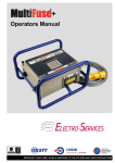
Module with serial number prefix 3221A. See Figure 3-1 for locations of
mechanical parts.
Replaceable Parts 3-1
Table 3-1. Agilent E1330A Replaceable Parts
Reference
Designator
Agilent Part
Number
Qty
Part Description
Mfr.
Code
Mfr. Part
Number
ASSEMBLIES and CABLES
(See Figure 3-1)
E1330-66201
1
REPLACEMENT ASSEMBLY
28480
E1330-66201
A1
E1330-66501
1
PC Assembly - Digital I/O 32-Channel
28480
E1330-66501
CBL1
E1330-61603
1
Test Cable (issued with Service Kit)
28480
E1330-61603
CBL2-CBL3
E1330-61601
2
Ribbon Cable (not illustrated)
28480
E1330-61601
MP1
E1300-45101†
1
HNDL-KIT TOP, Agilent†
28480
E1300-45101†
MP2
E1300-45102†
1
HNDL-KIT BTM, VXI†
28480
E1300-45102†
F1
2110-0712
1
Fuse-subminiature 4A 125V NTD AX
75915
R251004T1
J1-J2
1252-1044
2
Connector-post type .100-pin-spcg 60-contact
76381
3372-5302
J12
1251-6515
1
Connector-post type .100-pin-spcg 6-contact
18873
67996-606
J15-J16
1251-4927
2
Connector-post type .100-pin-spcg 16-contact
76381
2416-6182TB
J51-J54
1251-4682
4
Connector-post type .100-pin-spcg 3-contact
27264
22-10-2031
P1
1252-1596
1
Connector-post type 2.54-pin-spcg 96-contact
00779
536010-5
P15
1258-0247
1
Four-position Jumper
22526
69146-204
P51-P57
1258-0141
7
Removable Jumper
00779
530153-2
PNL1
E1330-00212†
1
PNL-RR 4 CH DAC†
28480
E1330-00212†
SCR1-SCR2
0515-2140
2
SCR-THD-RLG M2.5 X0.45 14mm
28480
0515-2140
SCR3-SCR4
0515-1968
2
Screw M2.5 X 0.45 11mm-long pan-head
28480
0515-1968
SCR5-SCR6
0515-2743
2
SCR-FH M2.5 X 8 THREAD ROLLING
28480
0515-2743
SW1
3101-3066
1
Switch-dip Rocker 8-1A 0.15A 30 VDC
81073
76YY22968S
† These parts are not compatible with older version fixed handles or their corresponding front panels. To replace one or more of these
old parts, you must order all three new parts (Top and Bottom Handle Kits AND Front Panel).
3-2 Replaceable Parts
Table 3-2. Agilent E1330B Replaceable Parts
Reference
Designator
Agilent Part
Number
Qty
Part Description
Mfr.
Code
Mfr. Part
Number
ASSEMBLIES and CABLES
(See Figure 3-1)
A1
E1330-66202
1
REPLACEMENT ASSEMBLY
28480
E1330-66202
E1330-66521
1
PC Assembly - Digital I/O 32-Channel
28480
E1330-66521
CBL1
E1330-61603
1
Test Cable (issued with Service Kit)
28480
E1330-61603
CBL2-CBL3
E1330-61601
2
Ribbon Cable (not illustrated)
28480
E1330-61601
MP1
E1300-45101†
1
HNDL-KIT TOP, Agilent†
28480
E1300-45101†
MP2
E1300-45102†
1
HNDL-KIT BTM, VXI†
28480
E1300-45102†
F1
2110-0712
1
Fuse-subminiature 4A 125V NTD AX
75915
R251004T1
J1-J2
1252-1044
2
Connector-post type .100-pin-spcg 60-contact
76381
3372-5302
J12
1251-6515
1
Connector-post type .100-pin-spcg 6-contact
18873
67996-606
J15-J16
1251-4927
2
Connector-post type .100-pin-spcg 16-contact
76381
2416-6182TB
J51-J54
1251-4682
4
Connector-post type .100-pin-spcg 3-contact
27264
22-10-2031
P1
1252-1596
1
Connector-post type 2.54-pin-spcg 96-contact
00779
536010-5
P15
1258-0247
1
Four-position Jumper
22526
69146-204
P51-P57
1258-0141
7
Removable Jumper
00779
530153-2
PNL1
E1330-00212†
1
PNL-RR 4 CH DAC†
28480
E1330-00212†
SCR1-SCR2
0515-2140
2
SCR-THD-RLG M2.5 X0.45 14mm
28480
0515-2140
SCR3-SCR4
0515-1968
2
Screw M2.5 X 0.45 11mm-long pan-head
28480
0515-1968
SCR5-SCR6
0515-2743
2
SCR-FH M2.5 X 8 THREAD ROLLING
28480
0515-2743
SW1
3101-3066
1
Switch-dip Rocker 8-1A 0.15A 30 VDC
81073
76YY22968S
† These parts are not compatible with older version fixed handles or their corresponding front panels. To replace one or more of these
old parts, you must order all three new parts (Top and Bottom Handle Kits AND Front Panel).
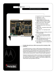
NOTE
If the 4 IC’s placed in the sockets are square in shape rather than
rectangular, the PC assembly (A1 reference designator) is the most recent
Agilent E1330B release, as listed above. If the 4 IC’s are rectangular (see
Figure 3-1), the PC assembly is an earlier E1330B release and must be
replaced with a new Replacement Assembly (Part Number E1330-66202).
Replaceable Parts 3-3
Table 3-3. Agilent E1330A/B Reference Designators
Agilent E1330A/B Reference Designators
A ..................................................assembly MP..................................... mechanical part
F........................................................... fuse P .........................electrical connector (plug)
J ......................... electrical connector (jack) PNL ....................................................panel
JM .................................................... jumper SCR................................................... screw
SW.................................................... switch
Table 3-4. Agilent E1330A/B Code List of Manufacturers
Mfr.
Code
Manufacturer’s
Name
Manufacturer’s
Address
Zip
Code
00779
AMP Inc.
Harrisburg
PA US
17111
18873
Dupont E I De Nemours & CO
Wilmington
DE US
19801
22526
Berg Electronics Inc.
Ettersill
PA US
17319
27264
Molex Inc.
Lisle
IL US
60532
CA US
94304
IL US
60016
MN US
55144
IL US
60525
28480
Agilent Technologies - Corporate
Palo Alto
75915
Littelfuse Inc.
Des Plaines
76381
3M CO
St Paul
81073
Grayhill Inc.
La Grange
3-4 Replaceable Parts
Mechanical
Parts
Locator
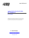
Figure 3-1 shows the location of selected mechanical parts for the Agilent
E1330A/B Quad 8-Bit Digital I/O Module.
Figure 3-1. Mechanical Parts
Replaceable Parts 3-5
3-6 Replaceable Parts
4
Service
Introduction
WARNING
Equipment
Required
Service Aids
Digital I/O Module
Description
This chapter contains service information for the Agilent E1330A/B Quad
8-Bit Digital I/O Modules. Also included are trouble shooting, repair, and
maintenance guidelines.
Do not perform any of the service procedures shown unless
you are a qualified, service-trained technician and have read
the WARNINGS and CAUTIONS in Chapter 1.
Equipment required for module troubleshooting and repair is listed in Table
1-1, Recommended Test Equipment. Any equipment that satisfies the
requirements given in the table may be substituted. To avoid damage to the
screw head slots, use a T8 Torx driver to remove the front panel handles.
See Chapter 3 — Replaceable Parts for descriptions and locations of
Agilent E1330A/B replaceable parts. Service notes, manual updates, and
service literature for the modules may be available through Agilent
Technologies. For information, contact your nearest Agilent Technologies
Sales and Service Office.
The Agilent E1330A/B provides four independent 8-bit digital I/O ports
compatible with TTL logic levels. Each port can be software configured for
operation as either input or output with either positive or negative true logic.
The ports can be combined to provide 16 bit (WORD) or 32 bit (LWORD)
operations.
In addition to the eight digital data lines, six handshake lines are included
per port. The handshake lines can also be combined (via jumpers on the
component assembly) to provide proper handshaking for combined ports.
The data lines of each port are provided with a jumpered pull-up resistors
for dry contact closure sensing. User connections to the Digital I/O module
are made through two 60-pin connectors on the rear panel.
Service 4-1
Repair Strategy
Agilent Technologies recommends replacement of the entire assembly in the
event of a failure. Procedures in this chapter describe troubleshooting
techniques.
Troubleshooting
Techniques
To troubleshoot an Agilent E1330A/B module problem you must first
identify the problem and then isolate the cause of the problem to a
replaceable assembly. See Chapter 3 — Replaceable Parts for descriptions
and locations of Agilent E1330A/B replaceable parts.
Identifying the
Problem
Table 4-1 lists some common problems for the Agilent E1330A/B modules,
along with symptoms and possible solutions. If the problem cannot be
identified using these steps, replace the assembly.
Table 4-1. Agilent E1330A/B Typical Problems
Symptom
Making Visual
Checks
Possible Solutions
Non-zero error code in
response to SYST:ERR?
See Appendix A of the Agilent
E1330A/B Quad 8-Bit Digital I/O Module
User’s Manual.
Module not responding to
commands.
See “Making Visual Checks” in this
chapter.
Module fails Digital Test
(Test 2-1).
See “Testing the Module” in this
chapter.
Visual checks for the Agilent E1330A/B modules include the following. See
Table 4-2 for typical checks.
• Check switches/jumpers
• Check for heat damage
• Check connector contacts
NOTE
4-2 Service
See the Agilent E1330A/B Quad 8-Bit Digital I/O Module User’s Manual
for information on logical address and IRQ settings. If there are no
apparent problems following the visual checks, run the Performance
Verification Tests in Chapter 2 to see if the module is defective.
Table 4-2. Agilent E1330A/B Visual Tests/Checks
Test/Check
Reference
Designator
Check
Action/Notes
Heat Damage
-------------
Discolored PC boards
Damaged insulation
Evidence of arcing
If there is damage, do not
operate the module until you
have corrected the problem.
Switch/Jumper
Settings
J15, J16
SW1
J51,J52,J53,J54
J12
IRQ Level setting
Logical address setting
Pull-up Enable
FLG Combine
Factory set at 1
Factory set at 144
Factory set to Enable
Factory set to no jumpers
Component
Assembly
F1
J1-J2
P1
Fuse continuity
Dirty or bent connector pins
Dirty or bent connector pins
Check fuse with ohmmeter
Straighten/clean pins
Straighten/clean pins
Testing the Module
You can use the tests and checks in Chapter 2 — Verification Tests, to
identify a problem with the assembly. See Chapter 3 — Replaceable Parts
for locations of mechanical parts.
Service 4-3
Repair and
Maintenance
Guidelines
ESD Precautions
This section provides guidelines for repairing and maintaining the Agilent
E1330A/B Quad 8-Bit Digital I/O Module including:
• ESD precautions
• Soldering printed circuit boards
• Post-repair safety checks
Electrostatic discharge (ESD) may damage static sensitive devices in the
module. This damage can range from slight parameter degradation to
catastrophic failure. When handling the module observe the following
guidelines:
• Always use a static-free work station with a pad of conductive rubber or
similar material when handling module components.
• If a device requires soldering, be sure the assembly is placed on a pad of
conductive material. Also, be sure that you, the pad, and the soldering
iron tip are grounded to the assembly.
Soldering Printed
Circuit Boards
The etched circuit board of this module has plated-through holes that
provide a solder path to both sides of the insulating material. Soldering can
be done from either side of the board with equally good results. When
soldering to any circuit board, keep in mind the following guidelines:
• Avoid unnecessary component unsoldering and soldering. Excessive
replacement can result in damage to the circuit board, adjacent
components, or both.
• Do not use a high power soldering iron on etched circuit boards, as
excessive heat may lift a conductor or damage the board.
• Use a suction device or wooden toothpick to remove solder from
component mounting holes. When using a suction device, be sure that the
equipment is properly grounded.
Post-Repair Safety
Checks
4-4 Service
After making repairs to the module, inspect the module for any signs of
abnormal internally generated heat, such as discolored printed circuit boards
or components, damaged insulation, or evidence of arcing. Determine and
correct the cause of the condition. Then perform Test 2-1 as described in
Chapter 2 — Verification Tests to verify that the module is functional.
A
Verification Tests - C Programs
Functional
Verification
Test
Example
This program is designed to do the Functional Verification Test found in
Chapter 2 - Verification Tests.
This example sends a *IDN? command to the Digital I/O Module. This test
can be used to verify that the module is connected properly and is
responding to a basic command.
#include <stdio.h>
#include <sicl.h>
#define ADDR "hpib7,9,18"
/* Address of Device */
void main ()
{
INST id;
char a[256] = {0};
/* Define id as an instrument */
/* Result variable */
id = iopen (ADDR);
/* Open instrument session */
ipromptf (id, "*IDN?\n", "%t", a);
/* ID command */
printf ("\n %s", a);
/* Print result */
getchar ();
/* Pause */
iclose (id);
/* Close instrument session */
}
Example C Programs A-1
Performance
Verification
Test
Example:
Digital Test
This program is designed to do the Performance Verification Test found in
Chapter 2 - Verification Tests.
This example performs a bit walk test of all bits on all ports and checks the
module’s ability to set and reset the handshake lines on each port.
/* Digital I/O Test
E1330A */
#include <stdio.h>
#include <stdlib.h>
#include <sicl.h>
#define ADDR "hpib7,9,18"
/* Address of device */
void main (void)
{
INST id;
/* Define id as an instrument */
char a[255], b[32];
char *bit_walk[] = {"00000001", "00000010", "00000100", "00001000",
"00010000", "00100000", "01000000", "10000000"};
int bit_val[] = {1, 2, 4, 8, 16, 32, 64, 128};
int fail, i, j, number;
int atoi (const char *a);
#if defined(__BORLANDC__) && !defined(__WIN32__)
_InitEasyWin();
#endif
ionerror(I_ERROR_EXIT);
id = iopen (ADDR);
/* Open instrument session */
iprintf (id, "*CLS\n");
fail = 0;
printf("\nInstall component assembly and test cable");
printf("\n\n 1. Turn mainframe power off");
printf("\n 2. Install E1330A/B component assemby into
mainframe");
printf("\n 3. Attach test cable to component assembly");
printf("\n 4. Turn mainframe power on");
printf("\n 5. Press ENTER when ready to begin testing");
gets (a);
/*-----------------------------------Bit walk test-------------------------------------*/
A-2 Example C Programs
printf("\n\nBit walk test of all ports for read and write (no handshake)");
for (i = 0; i <= 7; i++)
{
for (j = 0; j <= 3; j++)
{
iprintf (id, "SOUR:DIG:DATA%u #B%s\n", j, bit_walk[i]);
if (j < 2)
iprintf (id, "MEAS:DIG:DATA%u?\n", j+2);
else
iprintf (id, "MEAS:DIG:DATA%u?\n", j-2);
iscanf(id, "%t", a);
number = atoi(a);
if (number != bit_val[i])
{
fail = 1;
printf("\nFailure of bit walk");
printf("\n WRITE at port %u", j);
if (j < 2)
printf("\n READ at port %u", j+2);
else
printf("\n READ at port %u", j-2);
}
}
}
printf("\nEnd of bit walk test");
/*---------------------------------Handshake line test-----------------------------*/
printf("\n\nHandshake line test");
(j = 1; j >= 0; j = j - 1)
{
for (i = 0; i <= 3; i++)
{
iprintf(id, "SOUR:DIG:CONT%u %u\n", i, j);
if (i < 2)
iprintf(id, "MEAS:DIG:FLAG%u?\n", i+2);
else
iprintf(id, "MEAS:DIG:FLAG%u?\n", i-2);
iscanf(id, "%1t", a);
if (atoi(a) != j)
{
fail = 1;
printf("\nFailure of handshake lines");
if (i < 2)
printf("\n CTL line on port %u to FLG line on port %u", i, i+2);
else
printf("\n CTL line on port %u to FLG line on port %u", i, i-2);
Example C Programs A-3
}
}
}
printf("\nEnd of handshake line test\n");
/*------------------------------------Results----------------------------------------------*/
if (fail == 0)
printf("\nDigital I/O PASSED all tests");
else
printf("\nDigital I/O failed tests");
iclose (id);
}
A-4 Example C Programs
/* Close instrument session */