1
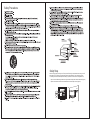
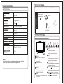
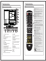
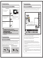
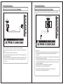
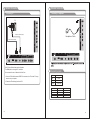
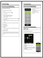
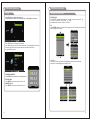
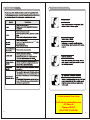
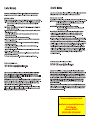
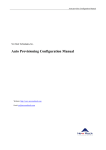
DECK13DR
For Sales Information Please Contact
RoadTrucker Inc (www.RoadTrucker.com)
8312 Sidbury Rd.
Wilmington, NC 28411
(800) 507-0482 / (910) 686-4281
Safety Precautions
Safety Strap
Caution: Pushing, pulling or climbing on the TV may cause the TV falling. Do not let chlidren climb or hang on the TV.
Always place the TV on a sturdy, level, sable surface that can hold the weight of TV. And if possible, secure the
TV according to the instruction below (Note: The fastening components such as screws are not supplied with TV).
Step one: Insert the M4 mounting screws into the upper two wall mounting screw holes and fasten them (Figure A).
Step two: Insert anchors to wall and connect the bolts and anchors with ropes or chains (Figure B).
Wall
M4 Screws
Figure A
Figure B
Caution and Warning
CAUTION
RISK OF ELECTRI C SHOC K
DO NOT OPEN
symbol, within an equilateral triangle
is intended to alert the user to the
presence of uninsulated dangerous
voltage within the product enclosure
consitute a risk of electric shock.
The exclamation point within an
equilateral triangle is intended to
alert the user to the presence of
important operating and maintenance
(servicing) instructions in the literature
accompanying the TV.
WARNING: TO REDUCE THE RISK OF FIRE OR ELECTRIC SHOCK, DO NOT EXPOSE THIS APPLIANCE TO RAIN
OR MOISTURE.
CAUTION: CHANGES OR MODIFICATIONS NOT EXPRESSLY APPROVED BY THE PARTY RESPONSIBLE FOR
COMPLIANCE WITH THE FCC RULES COULD AVOID THE USERS AUTHORITY TO OPERATE THIS
EQUIPMENT.
FCC Notice
FCC Information
The MAINS plug or an appliance coupler is used as the
disconnect device, The disconnect device shall remain
readily operable.
This equipment has been tested and found to comply with the limits for a Class B digital device, pursuant to Part 15 of
the FCC rules. These limits are designed to provide reasonable protection against harmful interference in a residential
installation. This equipment generates, uses and can radiate radio frequency energy and, if not installed and used in
accordance with the instructions, may cause harmful interference to radio Communications. However, there is no
Guarantee that interference will not occur in a particular installation. If this equipment does cause harmful interference
to radio or television reception, which can be determined by turning the equipment off and on, the user is encouraged
to try to correct the interference by one or more of the following measures:
- Reorient or relocate the receiving antenna.
- Increase the separation between the equipment and the receiver.
- Connect the equipment into an outlet on a circuit different from that to which the receiver is connected.
- Consult the dealer or an experienced radio/TV technician for help.
The TV set should not be subjected to water droplets,
vapor, or splash. This equipment should not be placed
on objects filled with liquids. Do not place flame sources,
such as lit candles, on or near the LED TV. Please, pull
out the power plug and contact after sales support if there
are abnormal objects or water in the TV.
Table of Contents
Introduction
Features
Specifications
Accessories
General Description
Overview of front and side panel
Overview of back panel
Overview of remote control
Installing Batteries in the Remote Control
WFeatures
arnings
2
3
4
4-7
4
5
6
7
External Connection
Connecting VCR
Connecting DVD Player/Set-Top Box
Connecting Digital Audio System
Connecting Amplifier/DVD Home Theater
Connecting DVD Player/Set-Top Box via HDMI
Connecting PC
Connecting a Headphone
8
Basic operation
15
Turning the TV On and Off
OSD Menu Operations
BASIC OPERATION
1
Introduction
8
9
10
11
12
13
14
15
16
16
CHANNEL
16
PICTURE
17
AUDIO
17
TIME
SETUP
LOCK
18
18
19-20
USB
21
USB Operation
22
DVD Setup Menu
23
USB/SD OPERATION
24
Troubleshooting
25
Picture defects and the reason
26
l
TV adopts TFT LED display screen
l
HDTV Compatible( 480p,720p, 1080i, 1080p)
l
Support American TV Standard 8VSB/Free 64/256QAM,NTSC System, ATSC System
l
Connect to computer directly to realize TV/monitor combo.
l
Zero X radiation complies to green environment protection requirement
l
Advanced Chroma Processing
l
Closed captioning/PARENTAL LOCK
l
SAP/STEREO/MONO; ATSC.
l
HDMI input
l
USB input
Input terminals used for external equipment connection
One computer VGA/PC input
One AV input
One EARPHONE output
One ANTENNA input
One S-VIDEO input
One YPbPr input
One PC Audio input
One HDMI input
One USB input
One Coaxial output
One R/L Audio output
2
Accessories
Introduction
Please make sure the following items are included with your LED TV. If any items are
WSpecifications
arnings
missing, contact your dealer.
Color active matrix LED display
Model
DECK13DR
Remote Control &
Owner’
s
Batteries (AAAx 2)
Instructions
1366X768
Fine digital control
Power supply
DC 12V
3A
NTSC System, ATSC System
Adapter
Antenna: 2~69; Cable: 1~135 (Analog: 1-125,
Digital: 1-135)
Car charger cable
NTSC3.58
75W
(Unbalance)
General Description
2x5W
Overview of front and side panel
DC 3V (Two AAA size batteries)
7
6
5
4
10
9
8
18 W
13.6 x 4.7 x 11.6 inch
o
o
0C-40C
Note:
Design and specification modification maybe made at any time without
prior notice; all data and dimensions are approximations.
3
SPEAKER
REMOTE CONTROL SENSOR
Aim the remote control towards this
spot on the TV.
POWER INDICATOR
Green: In power on mode.
Red: In standby mode.
9
SOURCE
Toggles between all the available input
sources ( TV, AV, S-VIDEO, Component,
10
HDMI, VGA, DVD, USB)
MENU
Press to see an on-screen menu of your
TV's features.
CH+/Press to change channels.
In the on-screen menu, use the CH +/buttons as up/down arrow buttons.
VOL+/Press to increase or decrease the volume.
In the on-screen menu, use the VOL +/buttons as left/right arrow buttons.
POWER
Press POWER button to toggle between
normal and standby mode.
Press the button when the power is
on the disc will eject, Press button
again the disc is pulled in automatically.
After placed a disc in the disc tray,
press
button to play the disc,and
press
button twice to pause.
4
General Description
Overview of back panel
Overview of remote control
USB
General Description
EARPHONE
OUT
IN
12
11
R
RF
13
HDMI
1
2
VGA
3
PC
AUDIO
IN
4
1. POWER( DC 12V ) input
2. HDMI
Connect to the HDMI jack of a device
with an HDMI output.
3. VGA/PC IN
Connect to the video output jack on
your PC.
4. PC AUDIO
Y
IN
Pb
Pr
VIDEO
5
6
COAXIAL
9
IN
S-VIDEO
OUT
L
10
8
IN
L
R
7
8. S-VIDEO
Connect an S-VIDEO signal from a
camcorder or VCR...
9. COAXIAL
Connect to a Digital Audio devices.
10. AUDIO OUT
Connect to the audio output jacks
on your amplifier/home theater.
Audio input for external devices
11.RF
5. COMPONENT
Connect to an antenna or cable
Connect Component video.
NTSC & ATSC.
6. COMPOSITE VIDEO
12.EARPHONE
Video input for external devices, such
Connect a set of phone for private
as a camcorder or VCR.
listening
7. S-VIDEO COMPOSITE COMPONENT 13.USB
AUDIO
USB input
Audio inputs for external devices.
5
POWER: Turn the TV on or off.
MUTE: Press to mute the sound, Press again to regain
the sound.
0-9: Press 0-9 to selet a TV channel directly The channel
will change after 2 seconds. Applicable for entering page
number in teletext mode and so on.
-/--: Press this button firstly when the channel to be
selected is two or three figures (only DVD mode).
RETURN: Return to the previously viewed program.
P.MODE: Select the picture mode.
S.MODE: Select the sound mode.
SOURCE: Press to select signal source for TV.
VOL+/-: Press these two buttons to increase/decrease the
sound volume.
CH+/-: Press these two buttons to change channels
sequently.
▲▼◀▶/enter: Allows you to navigate the on-screen
menus and adjust the system settings to your
preference.
EXIT: Exit from the menu or sub menu.
MENU: Allow you to navigate the on-screen menus.
EPG: Press to display EPG (Electronic Program Guide) in
formation.
INFO: Displays the channel in formation.
ZOOM: Press to change the screen scale.
MTS: Press to select the audio channels.
LOCK: Press to display the parental menu.
: Open/close in DVD mode.
TIME: Press to display Time menu.
SETUP: DVD system setup.
FREEZE: Press to freeze the screen.
DISPLAY: Press to display the program’s in formation.
CC: Press to display the closed caption.
AUDIO: Press to display the language of the audio in DTV
or DVD mode.
LIST: Press to display the TV program list.
GOTO: Press this button to go to desired position The
player provides 3 search mode.
FAV: Press to display the favorite programs.
SUBTITLE: Press to select the subtitle language.
ADD: Add this program to the favorite language.
ERASE: Delete this program from the favorite channels
list.
REPEAT: Press to change the playing mode.
FAV+/-: Press this button +/- the favorite program list.
A-B: Repeat play the segment between A and B.
SLEEP: Set up the time how long the TV will turn off.
TIME: Press to display tine menu.
MENU: TV system setup.
PBC: Press this button can return to the menu of the disc,
then play the disc from the first track.
: Play / Pause.
: Stop playing.
:Play fast backward / forward.
: Play previous / next media file.
6
General Description
External Connection
Installing Batteries in the Remote Control
Connecting VCR
Installing Batteries
1
These instructions assume that you have already connected your TV to an antenna or a
cable TV system. Skip step 1 if you have not yet connected to an antenna or a cable
system.
Open the battery compartment
cover on the back side.
Put the used batteries into the recycling bin since it can negatively affect
the environment.
OUT
EARPHONE
Insert two 1.5V AAA size batteries in
correct polarity. Don´t mix old or used
batteries with new ones.
VCR Rear Panel
RF
2
Point the remote towards the remote
control sensor of the wireless TV and
use it within 7 meters.
IN
Cover
USB
Battery
OUT
L
R
2xsize AAA 1.5V
3
Closed the cover.
COAXIAL
Audio Cable (Not supplied)
Video Cable (Not supplied)
Battery
Cover
HDMI
The batteries shall not be eposed to ecessive heat such as sunshine
fire of the like.
External Connection
VGA
PC
AUDIO
IN
Y
IN
Pb
Pr
VIDEO
IN
L
IN
S-VIDEO
RF Cable (Not supplied)
R
Follow the instructions in Viewing a VCR or Camcorder Tape to view your VCR tape.
Each VCR has a different back panel configuration.
When connecting a VCR, match the color of the connection terminal to the cable.
We recommend the use of cables with a Ferrite Core.
Antenna connection
Antenna input impedance of this unit is 75ohm. VHF/UHF 75ohm coaxial cable can be
connected to the antenna jack directly, if the antenna cable is 300ohm parallel flat feeder
cable, you need to use the 300ohm/75ohm converter to connect the antenna cable to the
antenna jack. For details Please refer to the following drawing.
Antennas with 75ohm Round Leads
Antennas with 30ohm flat twins Leads
Use a 75ohm - 300ohm converter
ANT IN
75ohm coaxial cable
300ohm coaxial cable
Antenna cable
1. Unplug the cable or antenna from the back of the TV.
2. Connect the cable or antenna to the ANT IN terminal on the back of the VCR.
3. Connect an RF Cable between the ANT OUT terminal on the VCR and the ANT IN
terminal on the TV.
4. Connect a Video Cable between the VIDEO OUT jack on the VCR and the VIDEO IN
jack on the TV.
5. Connect Audio Cables between the AUDIO OUT jacks on the VCR and the AUDIO L and
AUDIO R jacks on the TV.
If you have a mono (non-stereo) VCR, use a Y-connector (not supplied) to hook up to
the right and left audio input jacks of the TV. If your VCR is stereo, you must connect
two cables.
Antenna feeder
9
10
External Connection
External Connection
Connecting DVD Player/Set-Top Box
Connecting Digital Audio System
The rear panel jacks on your TV make it easy to connect a Digital Audio System to your TV.
The rear panel jacks on your TV make it easy to connect a DVD to your TV.
VGA
PC
AUDIO
IN
Y
IN
Pb
Pr
VIDEO
IN
L
OUT
R
OUT
L
IN
COAXIAL
HDMI
HDMI
S-VIDEO
OUT
L
COAXIAL
COAXIAL Cable (Not supplied)
IN
S-VIDEO
Component Cable (Not supplied)
IN
RF
OUT
R
Audio Cable (Not supplied)
Digital Audio System
IN
RF
EARPHONE
USB
EARPHONE
USB
DVD Player/Set-Top Box
VGA
PC
AUDIO
IN
Y
IN
Pb
Pr
VIDEO
IN
L
R
R
Component video separates the video into Y (Luminance (brightness)), Pb (Blue) and Pr
(Red) for enhanced video quality.
Be sure to match the component video and audio connections.
For example, if connecting the video cable to COMPONENT IN, connect the audio
cable to COMPONENT IN also.
Each DVD player/STB has a different back panel configuration.
When connecting a DVD player/STB, match the color of the connection terminal to the
cable.
We recommend the use of cables with a Ferrite Core.
5.1 CH audio is possible when the TV is connected to an external device supporting 5.1
CH.
We recommend the use of cables with a Ferrite Core.
1. Connect an COAXIAL Cable between the SPDIF jacks on the TV and the Digital Audio
Input jacks on the Digital Audio System. When a Digital Audio System is connected to the
SPDIF terminal: Decrease the gain (volume) of the TV, and adjust the volume level with
the system's volume can’t control.
1. Connect a Component Cable between the COMPONENT IN [Y, PB, PR] jacks on
the TV and the COMPONENT [Y, PB, PR] jacks on the DVD player.
2. Connect Audio Cables between the COMPONENT IN [R-AUDIO-L] jacks on the TV
and the AUDIO OUT jacks on the DVD player.
11
12
External Connection
External Connection
Connecting Amplifier/DVD Home Theater
Connecting DVD Player/Set-Top Box via HDMI
USB
EARPHONE
OUT
IN
OUT
COAXIAL
OUT
L
COAXIAL
OUT
L
R
R
RF
RF
Amplifier
DVD Player/Set-Top Box
IN
EARPHONE
USB
This connection can only be made if there is a HDMI Output connector on the external
device.
Audio Cable (Not supplied)
HDMI
VGA
PC
AUDIO
IN
Y
IN
Pb
Pr
VIDEO
IN
L
IN
S-VIDEO
IN
S-VIDEO
HDMI Cable (Not supplied)
R
HDMI
Each external input source device has a different back panel configuration.
When connecting an external device, match the color of the connection terminal to the
cable.
We recommend the use of cables with a Ferrite Core.
1. Connect Audio Cables between the AUDIO L and R OUT on the TV and AUDIO IN [RAUDIO-L]on the Amplifier.
When an audio amplifier is connected to the AV OUT [R-AUDIO-L] terminals: Decrease
the gain (volume) of the TV, and adjust the volume level with the Amplifier's volume
Can’t control.
VGA
PC
AUDIO
IN
Y
IN
Pb
Pr
VIDEO
IN
L
R
What is HDMI.
HDMI, or high-definition multimedia interface, is a next-generation interface that enables
the transmission of digital audio and video signals using a single cable without
compression.
Multimedia interface is a more accurate name for it especially because it allows multiple
channels of digital audio (5.1 channels).
The difference between HDMI and DVI is that the HDMI device is smaller in size, has the
HDCP(High Bandwidth Digital Copy Protection) coding feature installed, and supports
multi-channel digital audio.
Each DVD player/STB has a different back panel configuration.
We recommend the use of cables with a Ferrite Core.
1. Connect an HDMI Cable between the HDMI connector on the TV and the
HDMI connector on the DVD player/Set-Top Box.
13
14
External Connection
External Connection
EARPHONE
OUT
IN
RF
OUT
R
IN
RF
EARPHONE
USB
DateTraver
USB
PC
USB
Connecting a Headphone
Connecting PC
R
PC AUDIO Cable (Not supplied)
VGA
PC
AUDIO
IN
Y
IN
Pb
Pr
VIDEO
IN
L
COAXIAL
S-VIDEO
1. Connect a D-Sub Cable between RGB/PC IN connector on the TV and the PC output
connector on your computer.
PC
AUDIO
IN
Y
IN
Pb
Pr
VIDEO
IN
L
R
Supporting signals
Input
Mode
Air
8VSB
Cable
Free 64/256QAM
CVBS
VGA/PC
640x480/60Hz
800x600/60Hz
1024x768/60Hz
1360x768/60Hz
15
VGA
R
Each PC has a different back panel configuration.
The HDMI jacks do not support PC connection.
We recommend the use of cables with a Ferrite Core.
2. Connect the PC audio input jackc on the TV
IN
OUT
L
COAXIAL
IN
S-VIDEO
HDMI
HDMI
OUT
L
Headphone Cable
D-Sub Cable (Not supplied)
NTSC 3.58
Component
480p/60Hz
720p/60Hz
1080i/60Hz
1080p/60Hz
HDMI
480p/60Hz
720p/60Hz
1080i/60Hz
1080p/60Hz
16
1
Basic Operation
OSD Menu Operations
Turning the TV On and Off
Adjust the OSD Screen
How to turn the TV on or off
1. Insert the power cord plug into a polarized AC
outlet.
2. Press POWER button on the remote control or
button on the LED TV.
3. Normal picture will be displayed on the screen after
6 seconds. If no signal input, "No Signal" will be
displayed on the screen.
4. If temporary POWER off is required, press POWER button on the remote control or
button on the LED TV.
5. If you want to completely switch off the power for this unit, unplug the power cord plug
for this unit.
6. After switching off the unit, you should turn on the TV again at least 5 seconds later.
Status indication lamp
Green: In power on mode.
Red: In standby mode.
Auto power off
If there is no signal input in any Mode, the TV will automatically accesses the standby
state in about 15 minutes.
Memory before turning TV off
The settings of picture and the preset channels will be memorized at turning off the unit.
When being started up again, the unit will work according to the mode set before being
turned off.
Press SOURCE button to display the
input source list;
Press ▼/▲ button to select the input
source you want to watch;
Press ENTER button to enter the
input source;
INPUT SOURCE
TV
AV
S-VIDEO
Component
DVD
HDMI
PC
USB
ENTER
BASIC OPERATION
CHANNEL
Press MENU button to display the main menu.
Press◄ / ► button to select CHANNEL in the main menu, it will highlight the first option.
Air/Cable
Air
Auto Scan
Favorite
Show/Hide
L
Channel
Channel No.
Channel Label
DTV Signal
Bad
Auto Scan
Air/Cable
press ENTER buttons to select it Cable or Air.
AUTO SCAN
Auto Tuning can find out all effective channel automatically.
Press ▼/▲ to select Auto Tuning, then press ENTER to start
auto searching.
If you want to stop searching, press EXIT.
Scan all channels
Digital channel only
Analog channel only
MENU
17
ENTER
18
OSD Menu Operations
Adjust the OSD Screen
OSD Menu Operations
TIME
Press MENU button to display the main menu.
Press◄ / ► button to select TIME in the main menu, it will highlight the first option.
PICTURE
Press MENU button to display the main menu.
Press◄ / ► button to select PICTURE in the main menu, it will highlight the first option.
Sleep Timer
Atlantic
DST
Off
Time Format
L
Picture
Picture Mode
Standard
Color Mode
Normal
Zoom Mode
Normal
3DNR
Weak
DLC
On
PICTURE MENU
Press MENU to display the main menu, and press ◄ /► to select the Picture Menu.
Highlight the item and press ▼/▲ to select corresponding sub-menu.
Picture Mode: Dynamic/Standard/Soft/ Personal.
Color mode:This item can adjust the saturation of the color based on your own like.
Zoom mode: Four selectable Zoom Modes, Normal, Zoom, Cinema, Wide .
3DNR: Used for the noise reduction adjustment to get a better image effects.
DLC: Dynamic brightness control
AUDIO
24-hour
Auto Sync
On
Clock
WakeUp
2012/1/1 12:0
2012/1/1 12:0
TIME MENU
Press MENU to display the main menu, and press ◄ /► to select the Time Menu.
Sleep Timer: Select the time in minutes(5min,10min,15min,30min,60min,90min,
120min,180min,240min,Personal) that you want the TV to shut off automatically
after you set the time. Cancel by setting it to Off.
Time Zone: Set to choose the time belt.
DST: Press ENTER to select the DST on or off.
Time Format: Set to choose time display format
Auto Sync: Synchronous automatic
Clock:Press ENTER to set time.
Wake Up: Ending the state of sleep
SETUP
Press MENU button to display the main menu.
Press◄ / ► button to select AUDIO in the main menu, it will highlight the first option.
Equalizer
AudioL
Time L
Off
Time Zone
Press MENU button to display the main menu.
Press◄ / ► button to select SETUP in the main menu, it will highlight the first option.
Personal
Audio Language
English
Digital Output
Surround
PCM
Off
Audio Only
AVC
Off
Off
Menu Language English
Transparency
25%
Closed Caption
Restore Default
SetupL
AUDIO MENU
Press MENU to display the main menu, and press ◄ /► to select the Sound Menu.
Equalizer : Adjust audio frequency band.
Audio Language: Set the language.
Digital Output: Press ▼ button to highlight Digital Output. then press the enter
buton to select it .
Surround : Surround effect on or off.
Audio Only: Audio Only effect on or off.
AVC: When set the AVC on, quick volume change will be smoothed.
19
Setup Wizard
Blue Screen
Off
SETUP MENU
Press MENU to display the main menu , and press◄/► to select the Set u p Menu.
Menu Language: Set the OSD display language. (English/ French/ Spanish)
Transparency: Set transparency of OSD.
Closed Caption: Set to hide the caption
Restore Default: Recall the default setting.
Setup Wizard: Installation guide.
Blue Screen: Set the background color to blue or black when no input signal.
20
OSD Menu Operations
OSD Menu Operations
LOCK
Adjust the OSD Screen
Press MENU button to display the main menu.
Press◄ / ► button to select LOCK in the main menu, it will highlight the first option.
Parental Controls___
INPUT BLOCK
Press ENTER to display the Input Block , Press ▼ / ▲ button to select (TV、AV、
S-VIDEO、Component、DVD、HDMI、 PC、USB )
press◄/► button to select “UnBlock” or “Block”.
US
Press ENTER button for to enter to US ratings menu, which contains two sub-menus:
MPAA Rating and TV Rating.
Lock L
TV RATING
TV-Y
ALL
US
TV-Y7
ALL
TV
MPAA
TV-G
ALL
TV-PG
ALL
V
S
L
D
TV-14
ALL
V
S
L
D
TV-MA
ALL
V
S
L
FV
Block
Press MENU button to display the main menu.
Press ◄ / ► button to select Lock in the main menu. It will highlight the first option.
Enter the code 0000 to enter the parental menu (see the picture below),
or press MENU to cancel.
MPAA
G
PG
PG-13
R
NC-17
MENU
Change Password
System Lock
On
Unrated Lock
Off
Lock
N/A
MENU
CANADA
Press ENTER button for to enter to CANADA ratings menu, which contains two
sub-menus: Canada English and Canada French.
Input Block
Lock L
X
ENTER
US
Canada
RRT Setting
Reset RRT
Canada
Canada Eng
Enter Old Password
CHANGE PASSWORD
Press ENTER button and enter a new 4 digit password.
SYSTEM LOCK
Press ENTER to select the system lock on or off.
UNRATED LOCK
Press ENTER to select the Unrated lock on or off.
Canada Fre
Enter New Password
Confirm Password
MENU
Clear
Cancel
ENTER
Canada Eng
C
Canada Fre
G
C8+
8 ans+
G
13 ans+
PG
16 ans+
14+
18+
18 ans+
Lock
Lock
EXEMPT
EXEMPT
MENU
21
MENU
22
USB
USB
USB Operation
USB Operation
Note: Before operating Media menu, Plug in USB device, then press SOURCE
button to set the Input Source to USB.
Press ◄ / ► button to select Photo/Music , and then press ENTER button to enter.
Enter the model of scanning music can scan the music files, as shown below:
Choose PHOTO to enter the photo scan model, if there are many zones in mobile
equipment, it would shown below:
Pitch up the MP3 files, press Enter to play, as shown below, can setup the playing
more belong to the toolbar, such as: suspend, fast forward, fall speed, loop, etc.
Choose C zone, can scan the folder and photos.
Press◄ /►to select the different menu pages.
Press the remote control of ENTER to turn into the selected sub menu.
Press the remote control of MENU to come back the previous menu or quit.
Press the remote control of EXIT to exit menu directly.
Selected the photos, press Enter to show slides, press the Enter again will show
the toolbar of menu, as shown, can do various operating to the show slides,
for example: suspend, stop, play music etc.
23
24
USB/SD OPERATION
Interface Function
INITIAL SETTING(DVD)
1. TV Type: This product supports
output of various system, including
Multi, NTSC, PAL.
1. TV DISPLAY: Set the ratio of output
to the television signal options are:
Normal/PS(4:3 Pan Scan), Nomal/PS
(4:3 Letter Box), Wide the current
default settings is wide.
2. OSD Lang: Set the OSD Language
options.
3. CAPTION: Only the enclosed captions
on some DVD titles, Optional setting:
ON/OFF.
4. LAST MEMORY: Save the last to open
with the related options are: ON/OFF.
1. LT/RT: Logic Surround stereo
audio output. This matrix-based coding
process enables stereo audio tracks to
carry four channels(left, center, right
and surround) of audio data.
2. Stereo: Analog stereo audio output.
The player sends the subwoofer and
speech signals to your front right and
front left speakers.
25
PAL: Choose this settings if your DVD
player is connected to a PAL TV. The
default setting is PAL: NTSC: Choose
this settings if your DVD player is connected to a NTSC TV.
MULTU: Choose this settings if your
DVD player is connected to a multisystem TV.
2. Audio: DVD built-in disc dubbing
language selection options.
3. Subtitle: This player provides English
etc, languages as the built-in subtitle
language, when playing DVD, user may
hide the subtitle or choose any of them
as the present subtitle language.
4. Disc menu: DVD Disc language
selection options.
5. PARENTAL[DVD only]: This is to
disable the playing of specified DVDs
which are unsuitable for children. Some
DVDs are encoded with specific rating
level.
lf the rating level of the disc is higher
than that preset in the setup operation,
playback of the disc will be prohibited.
After selecting one of the PARENTAL
items the screen will change to the
PASSWORD page, and password is
8888.
6. PASSEORD[DVD only]: Change the
PASSWORD.
7. Default: This option will resume the
original settings of this player.
26
Troubleshooting
Picture defects and the reason
Snowy Picture
plugged in.
MUTE
been
8
For Sales Information Please Contact
27
RoadTrucker Inc (www.RoadTrucker.com)
8312 Sidbury Rd.
Wilmington, NC 28411
(800) 507-0482 / (910) 686-4281
28
For Sales Information Please Contact
RoadTrucker Inc (www.RoadTrucker.com)
8312 Sidbury Rd.
Wilmington, NC 28411
(800) 507-0482 / (910) 686-4281