1
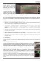
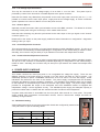
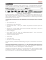
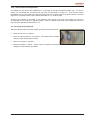
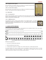
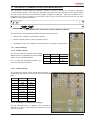
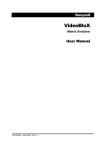
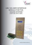
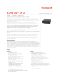
VideoBloX Matrix Switcher
User’s Manual
Revision 29 May 2002
1. INTRODUCTION
8. VIDEO OUTPUT MODULES
2. SYSTEM OVERVIEW
9. TITLED VIDEO OUTPUT MODULE
9.1. DIP Switch Settings
9.2. Adjustments
9.2.1. Display Width
9.2.2. Display Color Burst Frequency
9.2.3. Real Time Clock Frequency
9.2.4. Video Output Gain
9.3. Restoring factory Defaults
3. RACK MOUNT SYSTEM CHASSIS
3.1. Connections
3.1.1. Main Input Power Connection
3.1.2. Low Voltage Input Connection
3.1.3. Chassis Sync I?n
3.1.4. Control Expansion Connector
3.1.5. Communications Expansion
4. POWER SUPPLY MODULE
4.1. DIP Switch Setting
4.2. Reset Push Button
4.3. Indications
4.4. Sync Phase Adjustment
4.5. Chassis Expansion Driver Board
5. CPU MODULE
5.1. DIP Switch Settings
5.2. Push Buttons
5.3. LED Indications
5.4. Adjustments
5.4.1. Display Width
5.4.2. Display Color Burst Frequency
5.4.3. Real Time Clock Frequency
5.4. Jumper Settings
5.5. Fuses
5.6. Connections
6. COMBO CPU MODULE
6.1. DIP Switch Settings
6.2. Push Buttons
6.3. LED Indications
6.4. Jumper Settings
6.4.1. Restoring Factory Defaults
10. AUDIO INPUT MODULE
10.1. DIP Switch Settings
10.2. Configuration Jumpers
10.2.1. Phantom Power Jumpers
10.2.2. 20dB Pad Jumpers
10.2.3. High Pass Filter Jumpers
10.2.4. Low Pass Filter Jumpers
10.3. Adjustments
10.3.1. Gain Adjustment
10.3.2. CMRR Adjustment
11. AUDIO OUTPUT MODULE
12. CHASSIS INTERLINK INPUT AND OUTPUT MODULE
12.1. DIP Switch Settings
13. SECONDARY COMMS EXPANSION MODULE
13.1. Jumper Settings
13.1.1. RS232 Settings
13.1.2. RS422 Settings
13.1.3. Backplane Communication
14. CPU ARBITRATION CONTROLLER MODULE
14.1. Operation
14.2. Connections
14.3. Switch Settings
14.4. Front Panel Push Button Operation
7. VIDEO INPUT MODULES
7.1. DIP Switch Settings
7.2. LED Indications
7.3. Adjustments
7.4. Fuses
7.5. Connections
Copyright The Video Factory (Pty) Ltd t/a Betatech 2002
All rights reserved. No part of this document may be reproduced by any means without the permission of
Betatech.
The information in this document is believed to be accurate in all respects. However Betatech assumes no
responsibility for consequences of the use thereof. All information is subject to change without notice.
VideoBloX User’s Manual Ver. 2.00
Page 2
1. INTRODUCTION
VideoBloX is a range of compatible building blocks for use in video surveillance and monitoring systems. An
entire system would consist of a suitable mix of the following components / modules:
z
Matrix chassis which are supplied complete with built in power supply units. These chassis are
available in industry standard 19 inch 2U, 4U, 8U and 12U rack mount enclosures. The 2U chassis is
powered by a low voltage power supply, while all other chassis may be powered from low voltage supply
or main input power supply.
z
VideoBloX CPU module. This card contains a high speed embedded microprocessor and the required
support circuitry and is used for the control of the entire system.
z
Video input modules. These provide protection and signal conditioning for 16 video inputs as well as
matrix switching of these inputs. All video inputs to the system are via these modules.
z
Video output modules. These provide protection and signal conditioning for up to 16 video outputs. The
units are available in 8 channel and 16 channel versions, each of which may optionally include
independent video titling on each output.
The entire system is based on a modular approach allowing for flexibility in configuring video control systems
to suit a wide variety of applications.
2. SYSTEM OVERVIEW
The configuration of a video surveillance / monitoring control system is highly dependent on the operational
requirements of the system. The modular building block approach allows for different system configurations
to be readily set up to suit differing application requirements.
Each system must contain at least one VideoBloX chassis. It is possible to interconnect more than one
chassis either at the same location or at different locations with suitable data and video interlinks between the
various racks. The form of interlink is dependent on the system type and could be hard wired, fibre optics,
radio, microwave or other. If there are a large number of video sources at a location which is remote from
the monitoring location, then it is generally more cost effective to distribute the matrix switching system by
locating a sub-chassis at the remote site(/s). This principle can be repeated for any number of remote sites.
Regardless of the number of sub-chassis required for a system, there will generally be one chassis which is
allocated as being the system master. The master chassis must contain a CPU module.
Generally, all VideoBloX modules have their own on board local power supply units. All signal lines which run
to the field are protected against limited overvoltages. Where any processing is required, this is done to the
greatest possible extent in a distributed manner, with each module taking care of it's own housekeeping.
Local supply voltages are monitored and the module will be reset if the supply falls below the minimum
threshold. Watchdog timers monitor the operation of local CPU circuits and reset the circuits if a malfunction
is detected. Each module has a DIP switch which is used to set the module address and indications which
show the critical system operating parameters (power and communications). A broad range of diagnostics
for each module are provided.
3. RACK MOUNT SYSTEM CHASSIS
VideoBloX is housed in an industry standard 19" rack
mountable chassis. Various chassis heights are
available to allow for different sized systems. The
number of modules which may be fitted is shown in
the following table:
Chassis Height
Max Modules
Typical size
2U
3
32 into 8
4U
7
80 into 16 or 64 into 32
8U
15
192 into 32 or 160 into 64
12U
23
320 into 32 or 288 into 64
VideoBloX modules are mounted from the front of the
chassis. The modules are fitted horizontally to allow
for vertical system expansion. All modules (except the power supply module) are position independent.
VideoBloX User’s Manual Ver. 2.00
Page 3
Modules are "hot-swappable" and
may be removed and reinserted
with the power on. The power
supply module is fitted vertically
beside the other modules. This
module may not be removed with
the power switched on and is not
position independent.
A separate termination card is
inserted at the rear of the chassis.
Termination cards for BNC input /
output, D type connectors, alarm
connectors etc. are available. Although modules are position independent, it is necessary to match the
module with the termination card.
All commonly used adjustments are accessible from the front. Adjustments / switch settings which are made
once at the time of installation, or when major reconfiguration is carried out, are accessed by removing a
module.
The VideoBloX chassis incorporates the following components:
z
Backplane: The backplane provides for distribution of power and control signals as well as 64 audio or
video (or mixed) signals. The distance between modules is 1/2U.
z
Cooling System: VideoBloX is equipped with fans which provide forced cooling to ensure reliable
operation for a fully populated chassis in ambient temperatures up to 40 degrees Celsius. Highly
efficient, switch mode power supplies are used throughout, which minimises the power dissipated
internally.
z
Termination card mounting slots: Located on the rear of the VideoBloX chassis allowing for different style
termination cards to be fitted.
z
Module mounting slots: Located on the front of the VideoBloX chassis allowing for insertion of the full
range of VideoBloX modules, except the power supply unit.
z
Power supply slot: Allowing for insertion of the power supply module accessible from the front of the
VideoBloX chassis
3.1. Connections
The rear view of the 4U chassis is shown below. Note that the connections of the 8U and 12U chassis are
identical.
3.1.1. Main Input Power Connection
The main input power connection is made using a standard IEC power connector. This
should be connected to the main input power supply, which may be 50 or 60 Hz. Please
ensure that the mains voltage matches the voltage rating shown on the rear of the chassis.
The earth connection must also be mode. The mains input connector incorporates a fuse
holder which protects the main input power only. Note that the second fuse on the rear of
the chassis is for the low voltage input only.
Ideally the main input power supply should have low noise levels, minimum voltage
fluctuation and be protected against overvoltages such as those induced by lightning.
When reliable system operation is essential, the main input power supply should be derived
from an uninterruptable power supply (UPS).
Note that the chassis may alternatively be powered via the low voltage AC / DC connector
(see 3.1.2.). It is possible to connect both the main input power supply and the low voltage
supply, to ensure continuous system operation in the event of failure of one of the power
sources.
VideoBloX User’s Manual Ver. 2.00
Page 4
3.1.2. Low Voltage Input Connection
This may be connected to a low voltage supply of 12-24 VAC or 12 to 30 VDC. This power input is
protected by means of the fuse which is located adjacent to the power connector.
Note that the chassis may alternatively be powered via the main input power connector (see 3.1.1.). It is
possible to connect both the main input power supply and the low voltage supply, to ensure continuous
system operation in the event of failure of one of the power sources.
3.1.3. Chassis Sync In
Optionally connect the master video synchronisation source to this BNC connector. This allows for all video
switching to take place during the vertical sync of the master video source.
Note that video switching may also be synchronised to the mains input or the sync signal on the "Control"
connector (see 3.1.4).
Please refer to the section on the power supply module for further information on configuration / diagnostics
relating to the sync input.
3.1.4. Control Expansion Connector
This connector allows for connection of control signals between multiple VideoBloX chassis. The pin-out of
this connector is automatically modified depending on configuration for the chassis being a master or slave.
Generally, this connector may be wired pin to pin between one master and multiple slave chassis.
3.1.5. Communications Expansion Connector
This connector allows for connection of serial communications signals between multiple VideoBloX chassis.
The pin-out of this connector is automatically modified depending on configuration for the chassis being a
master or slave. Generally, this connector may be wired pin to pin between one master and multiple slave
chassis.
4. POWER SUPPLY MODULE
This module converts the main input power to an unregulated low voltage DC supply. There are two
different revisions of the power supply to provide a 115 VAC and a 240 VAC 50 / 60 Hz version. It is
additionally possible to power a VideoBloX chassis from a 12 to 24 VAC or 12 to 30 VAC supply. Power
indications are visible from the front of the chassis. The power supply is equipped with the necessary
protection and filtering to ensure regulatory compliance. It is possible to bring backup power into a chassis
so that operation is not affected by the failure of the main input power supply. The power supply module
provides an unregulated DC output to the backplane and each VideoBloX module is equipped with
independent voltage / current regulation circuitry. The VideoBloX power supply has adequate capacity to
power all modules within a chassis and also a limited number of external control keyboards.
A system reset push button is accessible from the front panel, after removal of a cover plate. The power
supply module also incorporates communication drivers, used to interconnect multiple sub-racks for
assembly of large matrices.
4.1. DIP Switch Setting
Various parameters which are common to the entire chassis are configured by means of the
4 way DIP switch as per the following tables:
Backplane Baud Rate
Switch 2
Switch 1
9600 Baud
Off
Off
19.2 KB (Default)
Off
On
57.6 KB
On
Off
115.2 KB
On
On
VideoBloX User’s Manual Ver. 2.00
Page 5
When multiple VideoBloX chassis are interconnected, use switch 4 to set the chassis which incorporates the
CPU card to be the master. All other chassis must be set up as slaves.
Use switch 3 to determine which chassis generates / receives the system synchronization signal. This signal is used to synchronize video matrix switch operations to occur during the vertical synchronization period
of the video signals.
Switch Position
Off
On
3
Chassis generates system sync signal
Chassis receives system sync signal
4
Chassis is a master
Chassis is a slave
4.2 Reset Push Button
When this button is pressed, the chassis will be reset. Should the chassis be configured as a master, then
all slave chassis will also receive a reset signal.
4.3. Indications
LED Name
Description
Tx Data
Flashes on when there is data present on the backplane transmit data line
Rx Data
Flashes on when there is data present on the backplane receive data line
RTS
Video Sync
Reset
Flashes on when the chassis is transmitting data
On when sync input is present
On when the reset signal on the backplane is active
4.4. Sync Phase Adjustment
This adjustment determines the sync phase with respect to the mains waveform. When sync is received via
the rear panel "Chassis Sync In" BNC or via the "Control" connector, this adjustment will have no effect
4.5. Chassis Expansion Driver Board
This is an optional PCB which plugs in to the power supply module. This board contains the drivers and
receivers which are necessary to interconnect master / slave chassis together. This is required when one or
more slave chassis are connected to a master chassis. For a system which uses only one chassis, this
optional board is not required.
Fitting Procedure:
z
Remove power from chassis
z
Remove 2 X fixing screws which secure power supply module to the front panel
z
Remove power supply module from chassis
z
Line up dual row connector on power supply board with expansion driver board.
z
Carefully press board into place.
z
Fasten board in place with 2 X M3 mounting screws.
z
Insert power supply into chassis, carefully lining up with the chassis connector. Press all the way in.
z
Re-fasten using 2 X fixing screws from step 2.
VideoBloX User’s Manual Ver. 2.00
Page 6
5. CPU MODULE
A VideoBloX system is controlled from a single master CPU module. For an expanded system, with multiple
chassis, it is possible to interconnect the chassis and have a single CPU module control the entire system.
Front and Rear Views of CPU Module
All system configuration is carried out by means of a PC running Windows 95 / 98 / 98SE / 2000 / XP or NT,
which connects to the CPU module. Once configuration is complete, the PC may optionally be detached or
used as a system activity logger. All configuration information is stored in non-volatile memory and is retained
during a power loss of up to one month.
The CPU module oversees the operation of all modules installed into a chassis or sub-chassis. The software
/ operating system is installed into this module. The following hardware sub-systems are located within this
module:
z
High speed processor core
z
EPROM memory to hold system firmware
z
Non-volatile RAM memory to store system variables, configuration and downloaded system code
extensions
z
Watchdog timer and supply voltage monitor to automatically restart system operation in the event of
supply brownouts or software malfunction
z
Various decoding logic
z
Power supplies for the CPU module only, including isolated supplies for the two communication
channels which connect to external equipment
z
Six serial communication channels
z
32 Alarm inputs
z
4 Alarm relay outputs
z
DIP switches for COM channel settings
Front panel indications provide basic information relating to the systems overall health and communications
activity.
It is possible to install multiple CPU modules into a single chassis. Should this be a requirement then an
additional CPU arbitration module must be installed. The arbitration module re-routes the major CPU
communications channels to the configuration PC and the field. Should a CPU failure be detected by the
arbitration module, the system can automatically switch over to the backup CPU.
Limited alarm inputs (32) and relay outputs (4) are provided on this module. Inputs and outputs may readily
be expanded by the addition of the relevant I2C expansion modules or remote expansion via the RS422
serial communications link. Up to 256 alarm inputs and 256 alarm outputs are supported.
VideoBloX User’s Manual Ver. 2.00
Page 7
The CPU module has dual processors. Six communications ports provide the following functions:
Port
Type
Description
Backplane
Open collector
Communications between CPU and various modules. Also expanded as
RS422 for interconnection between multiple racks. Expansion also used for
MVT (video titler) and various VCR / device controllers
Master
RS422
Connects to keyboards, PIT and PTZ using Betatech Bossware* protocol
Slave
Isolated RS232
Connects to PC for configuration, Operator’s GUI and logging
Aux
Isolated RS232
Connects to 3rd part equipment such as access control to allow for matrix
control
Concentrator
RS422
Reserved
Satellite
RS422
Connects to remote VideoBloX systems to allow “Networked”
* Bossware is the native protocol of the VideoBloX system.
5.1. DIP Switch Settings
The CPU has four
DIP switches which
are used to set up
various operational
parameters. These
switches
are
accessed by removal of the cover plate on the front of the CPU.
DIP switch 1 is used to set communications parameters for the RS232 PC communication / configuration port.
Switch Reference
Function
SW1/1
Least significant bit of unit address (A0)
SW1/2
Address (A1)
SW1/3
Address (A2)
SW1/4
Address (A3)
SW1/5
Address (A4)
SW1/6
Most Significant bit of unit address (A5)
SW1/7
SW1/8
PC / Config
Baud Rate
Off
Off
9600
Baud
On
Off
19.2
KBaud
Off
On
57.6
KBaud
On
On
115.2
KBaud
Note that the address is set in binary. For more information, please refer to Appendix A.
DIP switch 2 is used to set communications parameters for the RS232 auxiliary communication port.
Switch Reference
SW2/1
SW2/2
Function
Aux Port
Baud Rate
SW2/3
Reserved
SW2/4
Reserved
SW2/5
SW2/6
BossWare
Baud Rate
SW2/7
Reserved
SW2/8
Reserved
VideoBloX User’s Manual Ver. 2.00
Off
Off
Off
Off
9600
Baud
On
9600
Baud
On
Off
Off
19.2
KBaud
Off
19.2
KBaud
Off
On
On
57.6
KBaud
On
57.6
KBaud
On
On
On
115.2
KBaud
115.2
KBaud
Page 8
DIP switch 3 is used to set communications parameters for the RS422 satellite communication port and the
RS422 concentrator port.PC communication / configuration port.
Switch Reference
Function
SW3/1
Satellite
Baud Rate
SW3/2
SW3/3
Reserved
SW3/4
Reserved
SW3/5
Concentrator
Baud Rate
SW3/6
SW3/7
Reserved
SW3/8
Reserved
Off
Off
Off
Off
9600
Baud
On
9600
Baud
On
Off
Off
19.2
KBaud
Off
19.2
KBaud
Off
On
On
57.6
KBaud
On
57.6
KBaud
On
On
On
115.2
KBaud
115.2
KBaud
DIP switch 4 is used to set various parameters relating to the operation of the system as per the following
table.
Switch Reference
Function
SW4/1
Off => Skip channel on video loss
On => Include channel on video loss
SW4/2
Off => Title on Input
On => Title on Output
SW4/3
SW4/4
Video Loss
Source
Off
Off
Input
Card
On
MVT
Titler
Off
Off
On
Concentrator
SW4/5
On => Read back PTZ position (PTZ DC2000 only)
SW4/6
On => Warn user if duplicate view is selected
SW4/7
Reserved
SW4/8
On => Local matrix switch for Satellite configuration (i.e. only PTZ control is via satellite)
On
Ignore
On
5.2. Push Buttons
During normal operation, the front panel push buttons are used to select various diagnostic information
display.
Push Button
Left
Button Function
Select previous diagnostic parameter
Right
Select next diagnostic parameter
Up
Select previous diagnostic screen
Down
Select next diagnostic screen
If switches are depressed while the chassis is powered up (or reset), then additional functions are possible:
z
Left and right buttons simultaneously => restore factory defaults
VideoBloX User’s Manual Ver. 2.00
Page 9
5.3. LED Indications
The front panel LEDs are used to display power and communication activity as follows:
LED
LED Function
PWR
On => chassis has power
BP
Flashes for a change detected on the backplane, either a input card
changing between on-line / off line mode, or video being lost / restored
SLV
Flashes for a change detected on the Bossware slave channel, either
a PCK keypress or joystick movement
PC
Flashes for data received on the PC configuration port
AUX
Flashes for data received on the auxiliary port
CNC
Reserved
SAT
Flashes for data sent or received on the satellite port
5.4. Adjustments
5.4.1. Display Width Adjustment (C3)
This adjustment is used to set the horizontal width of the diagnostic video display output
5.4.2. Display Color Burst Frequency Adjustment (C5)
This adjustment is used to set the frequency of the color burst of the diagnostic video
display output. It should be set so that when a color video monitor is connected, the
diagnostic screen is shown in color. Adjustment is carried out by determining the positions
where the color information is lost and then setting the trimmer to midway between these
two positions.
5.4.3. Real Time Clock Frequency Adjustment (C131)
This adjustment may be used to trim the frequency of the real time clock in order to
provide the most accurate possible timekeeping. A frequency counter should be
connected to pin 7 of the IC marked "Real Time". The trimmer should then be set
to obtain a frequency of exactly 1 Hz.
5.4. Jumper Settings
JP 3,4 and 5 are used to select
alternate communications channels
on the backplane. Note that these
will generally be set for the primary
communications channel and will
only be changed when specialised
software is installed which utilises
the secondary communications
channel.
JP8 is used to allow CPU selection for use with the CPU arbitration module.
Jumper Position
JP8 Off
Function
The CPU is the only CPU in the chassis
JP8 Pos 1
The CPU is assigned as being CPU 1 within the chassis
JP8 Pos 2
The CPU is assigned as being CPU 2 within the chassis
VideoBloX User’s Manual Ver. 2.00
Page 10
JP10 is used to select NTSC / PAL mode of operation. Note that to change the mode, it is
necessary to change BOTH JP10 and the crystal Y1.
5.5. Fuses
The CPU card has 2 PCB mounted fuses, rated at 4A each. These fuses should only blow in the event of a
fault on the board. In such an event the CPU module should be returned to a Betatech distributor for repair.
5.6. Connections
All RS422 communications ports use the following pin-outs:
Pin
Master Mode
Slave Mode
1
RS422 TX[-]
RS422 RX[-]
2
RS422 TX[+]
RS422 RX[+]
3
RS422 RX[+]
RS422 TX[+]
4
RS422 RX[-]
RS422 TX[-]
5
RS422 common
RS422 common
6
Auxiliary power common
Auxiliary power common
7
Transmit Indicator TX[+]
Transmit Indicator RX[+]
8
Transmit Indicator TX[-]
Transmit Indicator RX[-]
9
Auxiliary power +ve
Auxiliary power +ve
All RS232 communications ports use the following pin-outs:
Pin
Pin Function
1
N/c
2
TXD
3
RXD
4
N/c
5
RS232 common
6
N/c
7
CTS
8
RTS
9
N/c
The I2C connectors have the following pin-outs:
Pin
Function
1
Common
2
I2C clock (SCL)
3
I2C data (SDA)
*4
+ 5 VDC
* => Use with caution, use a maximum of 4 VideoBloX compatible I2C expansion modules per port.
VideoBloX User’s Manual Ver. 2.00
Page 11
6. COMBO CPU MODULE
The Combo CPU is a reduced cost, scaled down version of the CPU module and additionally includes an 8
channel titled output section.
MATRIX COMBO CPU
Dip Switch Settings
Communication Activity
PWR
BP
SLV
PC
AUX
Front and Rear View of Combo CPU Module
The Combo CPU has the following limitations:
z
A single communications port is shared between the Auxliliary and Satellite ports. Only one of these
functions will therefore be possible.
z
A maximum size of 96 inputs by 8 outputs is supported.
z
Only 8 alarm inputs and 2 relay outputs are available. Alarm inputs may be expanded with local I2C
modules but the Combo CPU does not support expanded alarms brought into the system via a PIT alarm
concentrator.
z
The “Concentrator” communications port is not available.
6.1. DIP Switch Settings
The Combo CPU has two DIP switches which are used to
set up various operational parameters. These switches are
accessed by removal of the cover plate on the front of the
Combo CPU.
DIP switch 1 is used to set communications parameters for
the RS232 PC communication / configuration port.
Switch Reference
Function
SW1/1
Least significant bit of unit address (A0)
SW1/2
Address (A1)
SW1/3
Address (A2)
SW1/4
Address (A3)
SW1/5
SW1/6
SW1/7
SW1/8
PC / Config
Baud Rate
Off
Aux / Sat Port
Baud Rate
Off
Off
Off
9600
Baud
On
9600
Baud
On
Off
Off
19.2
KBaud
Off
19.2
KBaud
Off
On
On
57.6
KBaud
On
57.6
KBaud
On
On
On
115.2
KBaud
115.2
KBaud
Note that the address is set in binary. For more information, please refer to Appendix A.
VideoBloX User’s Manual Ver. 2.00
Page 12
DIP switch 2 is used to set communications parameters for the RS232 auxiliary communication port.
Switch Reference
Function
SW2/1
BossWare
Baud Rate
SW2/2
Off
Off
9600
Baud
On
Off
19.2
KBaud
Off
On
57.6
KBaud
On
On
SW2/3
Off => Skip channel on video loss
On => Include channel on video loss
SW2/4
Off => Select Auxiliary Port
On => Select Satellite Port
SW2/5
Reserved
SW2/6
Reserved
SW2/7
Reserved
SW2/8
Reserved
115.2
KBaud
6.2. Push Buttons
Operation if the Combo CPU front panel pushbuttons is similar to that of the CPU, described in section 5.2.
6.3. LED Indications
The front panel LEDs are used to display power and communication activity as follows:
LED
LED Function
PWR
On => chassis has power
BP
Flashes for a change detected on the backplane, either a input card
changing between on-line / off line mode, or video being lost / restored
SLV
Flashes for a change detected on the Bossware slave channel, either
a PCK keypress or joystick movement
PC
Flashes for data received on the PC configuration port
AUX
Flashes for data received on the auxiliary / satellite port
6.4. Jumper Settings
6.4.1. Restoring Factory Defaults
With the Combo CPU out of the rack and
disconnected from power,
z
Move jumper JP1 to position 2.
z
Leave it in this position for 10 seconds. This
clears the non-volatile memory of the Combo
CPU.
z
Return the jumper to position 1.
z
Reinstall Combo CPU in rack. When power is applied, the default settings will automatically be loaded.
VideoBloX User’s Manual Ver. 2.00
Page 13
7. VIDEO INPUT MODULES
The video input module brings 16 video signals into the VideoBloX chassis. Each of the inputs may be
routed to 1 or more of the 64 backplane channels. There are a range of different input modules providing
differing numbers of outputs, some of which have front panel termination switches and some of which have
internal termination jumpers.
VIDEO INPUT
PWR
Video Input Modules (2 front panel options)
There are a number of rear panel termination options
Video Input Modules (Standard - 16 BNC Inputs)
Video Input Modules (Looping BNC Inputs)
The looping card allows for looping of video inputs to another matrix switcher chassis or to an external video
device, such as a VCR, DVR or mulitiplexor. Note that if a looping termination card is installed, a blank cover
plate will be needed above the input card on the front of the chassis.
When a system requires more than 64 video outputs (the maximum which can be accomodated in a single
rack), cross-looping input rear termination modules may be used. These modules allow for a cross-connection of 8 video inputs from each the style ‘A’ and ‘C’ modules. When connected using coaxial ribbon cables,
each chassis receives all 16 video inputs. The ‘B’ style cross-connection module allows for interconnection
of up to 4 VideoBloX chassis.
Type A, B and C Cross-Connect Looping Input Termination Modules
VideoBloX input modules are equipped with:
z
Front panel mounted termination switch or internal termination switch (dependant on model)
z
Front panel accessible gain adjustment
z
Internal jumper selectable high frequency compensation
z
Video Loss detection. Allows triggering of event based on video loss and / or video restored.
z
Limited protection against over-voltages, such as those induced by a nearby lightning strike.
VideoBloX User’s Manual Ver. 2.00
Page 14
7.1. DIP Switch Settings
Dependant on the style of input module, DIP switches will be as per one of the following diagrams. Note that
the address is set in binary. For more information, please refer to Appendix A.
This diagram shows the DIP switch setting for the VBLX16M32 and VBLX16M64 modules.
z
Set the module address. This must be non-zero. A value of 1
addresses the card to accept video inputs 1 to 16, etc.
z
Turn on S2/1 to cause the modules to switch to outputs 65 to 128.
This will require the module to be fitted into a rack, associated with
outputs 65 to 128.
z
Turn on S2/2 to cause the module to work transparently as a slave
to another input module. In this mode, the module will not reply to
CPU messages. In this mode, it would be possible to have 3 similar matrix switchers, switching RGB video.
z
Turn on S2/3 to cause the module to automatically switch it’s 16 video inputs to 16 video outputs on power
up. In this mode, the address switch determines which group of outputs will be used. This allows for
using the modules to make large VDA’s, without the need for a CPU.
z
Turn on S2/4 to cause the module to enter test mode. In this mode, the module rapidly cycles various
inputs to outputs. This is useful for bench-top fault finding and should not normally be used in the field.
The diagrams alongside show the DIP settings on newer
revision input modules.
z
Set the module address as described above. Setting this to
zero causes the module to enter test mode. For test mode,
the “Input Group address” must also be zero.
z
The “Input Group Address” extends the address
range of the input module and may be
considered to be address selections “A8” and
“A9”. This is for use in future revisions of
software.
z
The “Output Group Address” determines which
group of 64 outputs the module will be associated with. This is for use in future revisions of
software.
z
“Switch 1 To 1” is as per “Route 1-1” above.
z
“Mute Reply” is as per “Review” above.
z
“Protocol B” is reserved for future use.
z
On 8 and 16 output cards, it is possible to route the channel 1 video sync signals to the backplane by use
of S2/8. This will then be used as a reference for video switch operations. This should only be used in
2U racks, as larger racks receive the synchronisation signal via the power supply.
VideoBloX User’s Manual Ver. 2.00
Page 15
7.2. LED Indications
The LED on the front panel of the input card illuminates to show power. Each time that a serial message is
received via the backplane and is addressed to the module, the LED will flash off briefly.
7.3. Adjustments
Each input has an adjustable gain which is used to adjust for differing levels of
the video input signal. This level should be set such that the input signal is
amplified to provide 2 volts (0.6V sync and 1.4V peak white) on the backplane,
when the backplane is terminated into an output card. Should the output card
be calibrated, then the input may be set to provide a 1 volt (0.3V sync and 0.7V
peak white) when terminated into a 75 ohm load.
The termination switch should be set to the 75 ohm position unless the input is
looped to other video products. Should the input be looped, then ensure that
the signal is terminated only at one position. The termination should always be
on the last video device.
7.4. Fuses
The input module has one PCB mounted fuse, rated at 4A. This fuse should only blow in the event of a fault
on the board. In such an event the input module should be returned to a Betatech distributor for repair.
7.5. Connections
Each video input is connected by means of a BNC connector mounted on the rear termination panel.
VideoBloX User’s Manual Ver. 2.00
Page 16
8. VIDEO OUTPUT MODULES
The video output module provides 16 video signals from the VideoBloX chassis. Each of the outputs is
associated with one of the 64 backplane channels.
8 and 16 Channel Video Output Modules - Front View
8 and 16 channel Video Output Rear Panel Termination Modules
Modules are equipped with:
z
Front panel accessible gain adjustment
z
Limited protection against over-voltages, such as those induced by a nearby lightning strike.
The output module has a range of jumpers which are populated to determine which group of 16 video
outputs the module receives from the backplane. These should not be modified by the user and output cards
should be ordered to cater for specific output channels.
VideoBloX User’s Manual Ver. 2.00
Page 17
9. TITLED VIDEO OUTPUT MODULE
The titled video output module provides 16 titled video signals from the VideoBloX chassis. Each of the
outputs is associated with one of the 64 backplane channels.
Front and Rear Views of Titled Video Output Module
Modules are equipped with:
z
24 character by 12 line text generation capability.
z
Built in real time clock.
z
Non-volatile RAM to retain camera titles during power down.
z
Limited protection against over-voltages, such as those induced by a nearby lightning strike.
9.1. DIP Switch Settings
Set the Titled Output Module DIP switches as follows:
z
Set the address to match the group of 16 outputs associated with
the module.
z
Set S1/7 On for NTSC or off for PAL. Note that the appropriate
frequency crystal must be installed in the module.
z
Turn on S1/8 to enter test mode. In this mode, text is displayed
which assists in setting the width adjustment.
9.2. Adjustments
9.2.1. Display Width Adjustment
Each titled output has an adjustment as shown alongside. This adjustment is used to set
the horizontal width of the on screen display video output. It should be adjusted so that
when the full width of the display is used (double sized characters), the spacing on the left
and right sides of the screen is uniform.
9.2.2. Display Color Burst Frequency Adjustment (C13)
This adjustment is used to set the frequency of the color burst which is common to
all on screen video display outputs. It should be set so that when a color video
monitor is connected, the on screen text is shown in color. Adjustment is carried
out by determining the positions where the color information is lost and then
setting the trimmer to midway between these two positions. Note that when a
video signal is routed through the system, the on screen text display will always be
in black and white. This adjustment must therefore be carried out in test mode.
9.2.3. Real Time Clock Frequency Adjustment
This adjustment may be used to trim the frequency of the real time clock in order to
provide the most accurate possible timekeeping.
VideoBloX User’s Manual Ver. 2.00
Page 18
9.2.4. Video Output Gain Adjustment
The default for the output level adjustment is to provide an overall normalised system gain. To set the
system for normalised gain first adjust the input gain as described in section 7.5. Then with the output
terminated into 75 ohms, adjust the rear panel gain so that the output signal level is the same as the input
signal level. Normally either of the methods described in 7.5. could be used.
Should it be required to generate a non-standard video signal level, such as boosting the signal to
compensate for long cable runs, adjust the gain in order to achieve the desired output signal once the input
gain has been adjusted as described in 7.5.
9.3. Restoring factory Defaults
With the output module out of the chassis and disconnected from power,
z
Move jumper JP2 to position 2.
z
Leave it in this position for 10 seconds. This clears the non-volatile
memory of the Titled Output module.
z
Return the jumper to position 1.
z
Reinstall module in chassis. When power is applied, the default
settings will automatically be loaded.
VideoBloX User’s Manual Ver. 2.00
Page 19
10. AUDIO INPUT MODULE
The audio input module brings 16 balanced audio signals into the VideoBloX chassis. Each of the inputs may
be routed to 1 or more of the 64 backplane channels.
Front and Rear Views of Audio Input Module
VideoBloX audio input modules are equipped with:
z
Balanced input capability
z
Front panel accessible gain adjustment
z
Front panel signal present and overload (peak) indications
z
Phantom powering option
z
20 dB pad to cater for a wide range of input signal levels.
z
High pass and low pass filter options
10.1. DIP Switch Settings
Set the Audio Input Module DIP switches as follows:
z
Set the module address. This must be non-zero. A value of 1
addresses the card to accept audio inputs 1 to 16, etc.
z
Turn on S2/1 to associate the module with output channels 65 to
128.
z
Turn on S2/2 to cause the module to work transparently as a slave
to another input module. This mode allows two cards to work
synchronously for switching stereo signals.
z
Turn on S2/3 to cause the module to automatically switch it’s 16
audio inputs to 16 audio outputs on power up. In this mode, the
address switch determines which group of outputs will be used.
z
Turn on S2/4 to cause the module to enter test mode. In this mode, the module rapidly cycles various
inputs to outputs. This is useful for bench-top fault finding and should not normally be used in the field.
10.2. Configuration Jumpers
10.2.1. Phantom Power Jumpers
Fit the two phantom power jumpers as per the legend shown alongside to provide
phantom powering for external microphones. In all other cases, these jumpers
should not be fitted.
10.2.2. 20dB Pad Jumpers
Adding the two 20 dB pad jumpers as per the legend alongside reduces the gain of
the audio input stage by 20 dB. This allows for high level audio inputs, such as line
level signals.
VideoBloX User’s Manual Ver. 2.00
Page 20
10.2.3. High Pass Filter Jumpers
Place the jumper in the position shown as “Hi Filter On” to enable the high pass filter
function. This reduces the level of signals below 300 Hz
10.2.4. Low Pass Filter Jumpers
Place the jumper in the position shown as “Low Filter On” to enable the low pass filter
function. This reduces the level of signals above 6000 Hz
10.3. Adjustments
10.3.1. Gain Adjustment
Adjust the front panel gain control to an optimum level for the input source for each channel. This level will
result in a bright LED indication for “Signal”, with only occassional flashes of the “Peak” LED when the input
signal is at the maximum expected level.
10.3.2. CMRR Adjustment
This adjustment sets the common mode rejection for the balanced inputs. It is factory
calibrated and should not be adjusted by the user. The optimum level is that where a
minimum output signal is obtained when both + and - input signals are driven by the identical
signal (inputs shorted).
11. AUDIO OUTPUT MODULE
The audio output module provides 16 audio output signals from the VideoBloX chassis. Each of the outputs
is associated with one of the 64 backplane channels.
OUTPUT
OUTPUT
Front and Rear Views of 8 and 16 Channel Audio Output Modules
Modules are equipped with:
z
Front panel accessible gain adjustment
z
Balanced (differential) signal output.
z
Limited protection against over-voltages, such as those induced by a nearby lightning strike.
The output module has a range of jumpers which are populated to determine which group of 16 audio
outputs the module receives from the backplane. These should not be modified by the user and audio
output cards should be ordered to cater for specific output channels.
VideoBloX User’s Manual Ver. 2.00
Page 21
12. CHASSIS INTERLINK INPUT AND OUTPUT MODULE
The Chassis Interlink Input and Output Modules allow for multiple chassis to be connected together to
increase the number of inputs of a matrix switching system.
Chassis Interlink Input Module
Chassis Interlink Output Module
Input and Output Interlink modules have the following features:
z
32 input / ouput channels, allowing for high density interconnects.
z
Balanced video driver and receivers allow high quality twisted pair connections for video.
The “Main” chassis of a matrix is that which incorporates the video output modules which connect to video
monitors. All other chassis are “Sub-Racks”, which use interlink modules to connect their backplane signals
to the main chassis.
There are no adjustments / DIP switches on the interlink output module. Factory fitted jumpers allow this
module to be available in two options, channel 1 to 32 and channel 33 to 64. Should a matrix be expanded
to more than 64 outputs, these two options are still used and refer to the backplane channels within each
sub-rack. Interlink outputs are connected to interlink inputs in the main chassis by means of twisted pair
ribbon cables, each carrying 16 signals.
12.1. DIP Switch Settings
Set the Interlink Input DIP switches as follows:
z
Set the “Start Address” (S2) to match the
address of the first input card within the
connected sub-chassis.
z
Set the “End Address” (S3) to match the
address of the last input card within the
connected sub-chassis.
z
Set S1/1 and S1/2 to determine which
group of 32 output signals will be
controlled by this module.
z
Turn on S1/4 to enter test mode. In this mode, the module rapidly cycles various inputs to outputs. This
is useful for bench-top fault finding and should not normally be used in the field.
VideoBloX User’s Manual Ver. 2.00
Page 22
13. SECONDARY COMMUNICATIONS EXPANSION MODULE
The Secondary Communications Expansion Module is used to access the secondary backplane
communications channel. This channel is generally used when two CPUs are fitted into the same chassis
and the second CPU has communications jumpers configured accordingly. Note that this differs from a
redundant CPU (See 14) where only one CPU is active at any one time and both CPUs use the same
backplane communications channel.
Front and Rear View of Secondary Comms Expansion Module
The Secondary Comms Expansion Module has the following features:
z
RS232 and / or RS422 communication options.
z
RS422 / RS232 master or slave connection pinout.
z
Capability to connect to backplane communications as a master or slave device.
13.1. Jumper Settings
13.1.1. RS232 Settings
JP1 and JP2 change the pinout of the RS232
DB9 connector, by swapping the TXD and RXD
signals as per the following table.
Pin 1, 4 and 6 are internally connected. Pin 7
and 8 are internally connected.
Pin
Slave
Master
2
TXD
RXD
3
RXD
RXD
5
Gnd
Gnd
13.1.2. RS422 Settings
JP3 changes the pinout of the RS422 DB9 connector, by
swapping the transmit and receive pairs as per the following
table.
Pin
Slave
Master
1
RX[-]
TX[-]
2
RX[+]
TX[+]
3
TX[+]
RX[+]
4
TX[-]
RX[-]
5
Gnd
Gnd
6
+24 VDC
+24 VDC
7
RTS[-]
RTS[-]
8
RTS[+]
RTS[+]
9
Gnd
Gnd
13.1.3. Backplane Communication Settings
Set the “BP Connection” to “Master” if the controller is
external or to “Slave” if this connection connects to a CPU
within the chassis.
VideoBloX User’s Manual Ver. 2.00
Page 23
14. CPU ARBITRATION CONTROLLER MODULE
The CPU Arbitration Module monitors the operation of the CPU in a VideoBloX matrix. Should a fault be
detected, the unit may be configured to automatically switch over to a second VideoBloX CPU.
Front and Rear View of CPU Arbitration Module
14.1. OPERATION
The Arbitration module has connectors to receive all relevant signals from the two CPUs to which it is
connected. The default mode (which will be selected with power off) is to select CPU A. Communications,
alarms, I2C expansion and diagnostic video are all routed via relays to field connections. It is possible to force
the Arbitration module to route either the connections from CPU A or those from CPU B by means of the front
panel CPU selection switch. When this switch is set to the "Auto Select" position, the system will
automatically monitor and select an appropriate CPU.
Typical Rear View of Arbitration Module and 2 CPU Modules in 4U Chassis
The VideoBloX CPU must be equipped with firmware revision 4.96 or later. The CPU has built in
functionality to monitor the status of communications activity and operation of the real time clock. The result
of the CPU health check is transmitted on the backplane communications channel.
The Arbitration module receives the system status information. Each time a valid message is received by the
Arbitration unit, the "BP" LED will flash. The received health check information is compared to the previous
status. Should a change be detected, the Arbitration module will check if the monitoring for the detected
status change is enabled. If a fault is detected an alarm will be sounded and a message displayed on the
Arbitration module. Should the CPU selection switch be in the "Auto" position, then the system will
VideoBloX User’s Manual Ver. 2.00
Page 24
automatically switch over to the alternate CPU. Switching will be inhibited if the alternate CPU currently
shows the same fault.
When a fault is detected, a buzzer will sound on the Arbitration module. The buzzer may be silenced by
pressing the "Buzzer Clear" button. Pressing the button for a second time, will remove the description of the
previous error from the Arbitration display.
To clear the Arbitration module internal error status, press and hold the "Buzzer Clear" button for 5 seconds.
The active CPU is indicated by illuminating either the "CPU A On" or "CPU B On" LEDs. Should one or more
errors be present on a CPU, the associated CPU fault LED will be illuminated.
14.2. CONNECTIONS
For a complete description of the functions and pin-outs of the connectors, please refer to section 5.
With Reference to the above rear view of the arbitration module in a 4U chassis.
z
All connections from CPU A are looped into the Arbitration connectors marked "Connect to CPU A".
z
All connections from CPU B are looped into the Arbitration connectors marked "Connect to CPU B".
z
Connections to field devices are connected to the Arbitration connectors marked "Connect to Field".
14.3. SWITCH SETTINGS
DIP switch S1 and S2 select which errors will be monitored by the Arbitration module. When a switch in on,
monitoring of the associated operation is enabled.
Switch S1 or S2 position
Monitoring Function
1
Backplane communications
2
Bossware master port communications
3
PC port communications
4
Auxiliary port communications
5
Concentrator port communications
6
Satellite port communications
7
Real time clock
8
Reserved
The remaining DIP switches are currently reserved
14.4. FRONT PANEL PUSH BUTTON OPERATION
VideoBloX User’s Manual Ver. 2.00
Page 25
The Arbitration module allows for viewing of the status of the attached CPUs. Selection of CPU is done by
pressing either the up or down arrow key.
Selection of the parameter to be displayed is done by pressing the left and right arrow keys. After
approximately 30 seconds, the system will automatically revert to the standard display mode. The following
parameters may be monitored:
Parameter
Description
Status
Zero for no faults of a hex representation of the combined fault status
Reset Count
The number of times the CPU has been restarted
Start Time
The date and time when the CPU was last restarted
End Time
The date and time when the CPU was last stopped
Backplane Comms
The error status for the backplane communications channel (see Note 1)
Master Comms
The error status for the master communications channel (see Note 1)
PC Comms
The error status for the PC communications channel (see Note 1)
Aux Comms
The error status for the auxiliary communications channel (see Note 1)
Concentrator Comms
The error status for the concentrator communications channel (see Note 1)
Satellite Comms
The error status for the satellite communications channel (see Note 1)
RTC Status
The error status for the real time clock (see Note 1)
Note 1: The display will read "OK" for no error, "Err" if an error is detected and "Masked" if an error is
detected BUT the associated function DIP switch is not enabled.
VideoBloX User’s Manual Ver. 2.00
Page 26
APPENDIX A BINARY ADDRESS VALUES
A8
A7
A6
A5
A4
A3
A2
A1
Unit Address
Off
Off
Off
Off
Off
Off
Off
Off
0 - not allowed
Off
Off
Off
Off
Off
Off
Off
On
1
Off
Off
Off
Off
Off
Off
On
Off
2
Off
Off
Off
Off
Off
Off
On
On
3
Off
Off
Off
Off
Off
On
Off
Off
4
Off
Off
Off
Off
Off
On
Off
On
5
Off
Off
Off
Off
Off
On
On
Off
6
Off
Off
Off
Off
Off
On
On
On
7
VideoBloX User’s Manual Ver. 2.00
Page 27