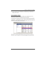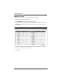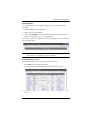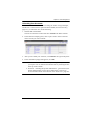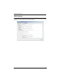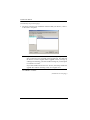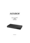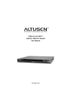
1
CC2000 Control Center Over the NET™ User Manual www.aten.com CC2000 User Manual FCC Information FEDERAL COMMUNICATIONS COMMISSION INTERFERENCE STATEMENT: This equipment has been tested and found to comply with the limits for a Class B digital service, pursuant to Part 15 of the FCC rules. These limits are designed to provide reasonable protection against harmful interference in a residential installation. Any changes or modifications made to this equipment may void the user’s authority to operate this equipment. This equipment generates, uses, and can radiate radio frequency energy. If not installed and used in accordance with the instructions, may cause harmful interference to radio communications. However, there is no guarantee that interference will not occur in a particular installation. If this equipment does cause harmful interference to radio or television reception, which can be determined by turning the equipment off and on, the user is encouraged to try to correct the interference by one or more of the following measures: Reorient or relocate the receiving antenna. Increase the separation between the equipment and receiver. Connect the equipment into an outlet on a circuit different from that to which the receiver is connected. Consult the dealer or an experienced radio/TV technician for help. FCC Caution: Any changes or modifications not expressly approved by the party responsible for compliance could void the user's authority to operate this equipment. RoHS This product is RoHS compliant. SJ/T 11364-2006 The following contains information that relates to China. ii CC2000 User Manual User Information Online Registration Be sure to register your product at our online support center: International http://eservice.aten.com Telephone Support For telephone support, call this number: International 886-2-8692-6959 China 86-10-5255-0110 Japan 81-3-5615-5811 Korea 82-2-467-6789 North America 1-888-999-ATEN ext 4988 United Kingdom 44-8-4481-58923 User Notice All information, documentation, and specifications contained in this manual are subject to change without prior notification by the manufacturer. The manufacturer makes no representations or warranties, either expressed or implied, with respect to the contents hereof and specifically disclaims any warranties as to merchantability or fitness for any particular purpose. Any of the manufacturer's software described in this manual is sold or licensed as is. Should the programs prove defective following their purchase, the buyer (and not the manufacturer, its distributor, or its dealer), assumes the entire cost of all necessary servicing, repair and any incidental or consequential damages resulting from any defect in the software. The manufacturer of this system is not responsible for any radio and/or TV interference caused by unauthorized modifications to this device. It is the responsibility of the user to correct such interference. The manufacturer is not responsible for any damage incurred in the operation of this system if the correct operational voltage setting was not selected prior to operation. PLEASE VERIFY THAT THE VOLTAGE SETTING IS CORRECT BEFORE USE. iii CC2000 User Manual Package Contents The CC2000 package consists of: 1 CC2000 USB License Key 1 Software CD 1 User Instructions* Check to make sure that all of the components are present and in good order. If anything is missing, or was damaged in shipping, contact your dealer. Read this manual thoroughly and follow the installation and operation procedures carefully to prevent any damage to the switch or to any other devices on the CC2000 installation. * Features may have been added to the CC2000 since this manual was published. Please visit our website to download the most up-to-date version. Copyright © 2008–2015 ATEN® International Co., Ltd. Manual Date: 2015/10/19 Altusen and the Altusen logo are registered trademarks of ATEN International Co., Ltd. All rights reserved. All other brand names and trademarks are the registered property of their respective owners. iv CC2000 User Manual Contents FCC, CE Information. . . . . . . . . . . . . . . . . . . . . . . . . . . . . . . . . . . . . . . . . . ii SJ/T 11364-2006. . . . . . . . . . . . . . . . . . . . . . . . . . . . . . . . . . . . . . . . . . . . . ii User Information . . . . . . . . . . . . . . . . . . . . . . . . . . . . . . . . . . . . . . . . . . . . .iii Online Registration . . . . . . . . . . . . . . . . . . . . . . . . . . . . . . . . . . . . . . . .iii Telephone Support . . . . . . . . . . . . . . . . . . . . . . . . . . . . . . . . . . . . . . . .iii User Notice . . . . . . . . . . . . . . . . . . . . . . . . . . . . . . . . . . . . . . . . . . . . . .iii Package Contents. . . . . . . . . . . . . . . . . . . . . . . . . . . . . . . . . . . . . . . . . . . iv About This Manual . . . . . . . . . . . . . . . . . . . . . . . . . . . . . . . . . . . . . . . . . .xiii Overview . . . . . . . . . . . . . . . . . . . . . . . . . . . . . . . . . . . . . . . . . . . . . . .xiii Conventions . . . . . . . . . . . . . . . . . . . . . . . . . . . . . . . . . . . . . . . . . . . .xiv Product Information. . . . . . . . . . . . . . . . . . . . . . . . . . . . . . . . . . . . . . . . . .xiv Important Note about Firmware . . . . . . . . . . . . . . . . . . . . . . . . . . . . . . . .xiv Chapter 1. Introduction Overview . . . . . . . . . . . . . . . . . . . . . . . . . . . . . . . . . . . . . . . . . . . . . . . . . . . 1 Features . . . . . . . . . . . . . . . . . . . . . . . . . . . . . . . . . . . . . . . . . . . . . . . . . . . 3 Secure Centralized Management . . . . . . . . . . . . . . . . . . . . . . . . . . . . . 3 Powerful Security . . . . . . . . . . . . . . . . . . . . . . . . . . . . . . . . . . . . . . . . . 5 Server Management Features. . . . . . . . . . . . . . . . . . . . . . . . . . . . . . . . 5 Requirements . . . . . . . . . . . . . . . . . . . . . . . . . . . . . . . . . . . . . . . . . . . . . . . 6 Server Requirements . . . . . . . . . . . . . . . . . . . . . . . . . . . . . . . . . . . . . . 6 Client Requirements . . . . . . . . . . . . . . . . . . . . . . . . . . . . . . . . . . . . . . . 7 Hardware Requirements . . . . . . . . . . . . . . . . . . . . . . . . . . . . . . . . . 7 Operating Systems . . . . . . . . . . . . . . . . . . . . . . . . . . . . . . . . . . . . . 7 Browsers . . . . . . . . . . . . . . . . . . . . . . . . . . . . . . . . . . . . . . . . . . . . . 8 Device Requirements . . . . . . . . . . . . . . . . . . . . . . . . . . . . . . . . . . . . . . 8 Licenses . . . . . . . . . . . . . . . . . . . . . . . . . . . . . . . . . . . . . . . . . . . . . . . . . . . 9 Nodes . . . . . . . . . . . . . . . . . . . . . . . . . . . . . . . . . . . . . . . . . . . . . . . . . . 9 Secondaries . . . . . . . . . . . . . . . . . . . . . . . . . . . . . . . . . . . . . . . . . . . . . 9 Chapter 2. CC2000 Server Installation Overview . . . . . . . . . . . . . . . . . . . . . . . . . . . . . . . . . . . . . . . . . . . . . . . . . . 11 CC1000 Considerations . . . . . . . . . . . . . . . . . . . . . . . . . . . . . . . . . . . . . . 11 Upgrading the CC1000 . . . . . . . . . . . . . . . . . . . . . . . . . . . . . . . . . . . . 11 Uninstalling the CC1000 . . . . . . . . . . . . . . . . . . . . . . . . . . . . . . . . . . . 11 Windows Version Installation . . . . . . . . . . . . . . . . . . . . . . . . . . . . . . . . . . 12 Before You Begin . . . . . . . . . . . . . . . . . . . . . . . . . . . . . . . . . . . . . . . . 12 Starting the Installation . . . . . . . . . . . . . . . . . . . . . . . . . . . . . . . . . . . . 12 Post-installation Check . . . . . . . . . . . . . . . . . . . . . . . . . . . . . . . . . . . . 17 Linux Version Installation . . . . . . . . . . . . . . . . . . . . . . . . . . . . . . . . . . . . . 18 Before you Begin . . . . . . . . . . . . . . . . . . . . . . . . . . . . . . . . . . . . . . . . . 18 Installing . . . . . . . . . . . . . . . . . . . . . . . . . . . . . . . . . . . . . . . . . . . . . . . 19 Post-installation Check . . . . . . . . . . . . . . . . . . . . . . . . . . . . . . . . . . . . 20 Post-Installation Setup . . . . . . . . . . . . . . . . . . . . . . . . . . . . . . . . . . . . . . . 20 Uninstalling the CC2000 . . . . . . . . . . . . . . . . . . . . . . . . . . . . . . . . . . . . . . 22 v CC2000 User Manual Uninstalling from a Windows System . . . . . . . . . . . . . . . . . . . . . . . . . 22 Uninstalling from a Linux System . . . . . . . . . . . . . . . . . . . . . . . . . . . . 22 Upgrading the CC2000 . . . . . . . . . . . . . . . . . . . . . . . . . . . . . . . . . . . . . . . 23 Preliminary Steps . . . . . . . . . . . . . . . . . . . . . . . . . . . . . . . . . . . . . . . . 23 CC2000 Secondary Servers . . . . . . . . . . . . . . . . . . . . . . . . . . . . . . . . . . . 24 CC2000 Redundant Secondary Servers . . . . . . . . . . . . . . . . . . . . . . . . . 24 Chapter 3. Browser Operation Logging In . . . . . . . . . . . . . . . . . . . . . . . . . . . . . . . . . . . . . . . . . . . . . . . . . 25 The CC Interface . . . . . . . . . . . . . . . . . . . . . . . . . . . . . . . . . . . . . . . . . . . 26 Screen Components . . . . . . . . . . . . . . . . . . . . . . . . . . . . . . . . . . . . . . 27 The Navigation Buttons. . . . . . . . . . . . . . . . . . . . . . . . . . . . . . . . . . . . 28 Tree View Considerations . . . . . . . . . . . . . . . . . . . . . . . . . . . . . . . . . . 29 Interactive Display Panel . . . . . . . . . . . . . . . . . . . . . . . . . . . . . . . . . . . . . 29 Overview . . . . . . . . . . . . . . . . . . . . . . . . . . . . . . . . . . . . . . . . . . . . . . . 29 Selecting List Items . . . . . . . . . . . . . . . . . . . . . . . . . . . . . . . . . . . . . . . 30 Preferences . . . . . . . . . . . . . . . . . . . . . . . . . . . . . . . . . . . . . . . . . . . . . . . 31 Web Options . . . . . . . . . . . . . . . . . . . . . . . . . . . . . . . . . . . . . . . . . . . . 32 Password . . . . . . . . . . . . . . . . . . . . . . . . . . . . . . . . . . . . . . . . . . . . . . 33 Notifications and Message Box . . . . . . . . . . . . . . . . . . . . . . . . . . . . . . . . 34 Chapter 4. Port Access Overview. . . . . . . . . . . . . . . . . . . . . . . . . . . . . . . . . . . . . . . . . . . . . . . . . . 35 Table Headings. . . . . . . . . . . . . . . . . . . . . . . . . . . . . . . . . . . . . . . . . . . . . 36 Action Buttons. . . . . . . . . . . . . . . . . . . . . . . . . . . . . . . . . . . . . . . . . . . . . . 37 Filter . . . . . . . . . . . . . . . . . . . . . . . . . . . . . . . . . . . . . . . . . . . . . . . . . . 37 Launch Multiviewer . . . . . . . . . . . . . . . . . . . . . . . . . . . . . . . . . . . . . . . 37 The Sidebar . . . . . . . . . . . . . . . . . . . . . . . . . . . . . . . . . . . . . . . . . . . . . . . 38 Sidebar Characteristics . . . . . . . . . . . . . . . . . . . . . . . . . . . . . . . . . . . . 38 Sidebar Filter. . . . . . . . . . . . . . . . . . . . . . . . . . . . . . . . . . . . . . . . . . . . 39 Port Operation . . . . . . . . . . . . . . . . . . . . . . . . . . . . . . . . . . . . . . . . . . . . . 40 CC Viewer . . . . . . . . . . . . . . . . . . . . . . . . . . . . . . . . . . . . . . . . . . . . . . 40 Web Access . . . . . . . . . . . . . . . . . . . . . . . . . . . . . . . . . . . . . . . . . . . . 41 Power ON / OFF . . . . . . . . . . . . . . . . . . . . . . . . . . . . . . . . . . . . . . . . . 42 SSH / Telnet Session . . . . . . . . . . . . . . . . . . . . . . . . . . . . . . . . . . . . . 42 Port Access Views . . . . . . . . . . . . . . . . . . . . . . . . . . . . . . . . . . . . . . . . . . 43 Port View. . . . . . . . . . . . . . . . . . . . . . . . . . . . . . . . . . . . . . . . . . . . . . . 43 Target View . . . . . . . . . . . . . . . . . . . . . . . . . . . . . . . . . . . . . . . . . . . . . 43 Device View . . . . . . . . . . . . . . . . . . . . . . . . . . . . . . . . . . . . . . . . . . . . 44 Department View. . . . . . . . . . . . . . . . . . . . . . . . . . . . . . . . . . . . . . . . . 44 Location View . . . . . . . . . . . . . . . . . . . . . . . . . . . . . . . . . . . . . . . . . . . 45 Type View . . . . . . . . . . . . . . . . . . . . . . . . . . . . . . . . . . . . . . . . . . . . . . 45 Favorites View. . . . . . . . . . . . . . . . . . . . . . . . . . . . . . . . . . . . . . . . . . . 46 Adding a Favorite . . . . . . . . . . . . . . . . . . . . . . . . . . . . . . . . . . . . . 46 Viewing a Favorite . . . . . . . . . . . . . . . . . . . . . . . . . . . . . . . . . . . . 47 Managing Favorites . . . . . . . . . . . . . . . . . . . . . . . . . . . . . . . . . . . . 48 Dashboard . . . . . . . . . . . . . . . . . . . . . . . . . . . . . . . . . . . . . . . . . . . . . . . . 49 User Preferences . . . . . . . . . . . . . . . . . . . . . . . . . . . . . . . . . . . . . . . . . . . 50 vi CC2000 User Manual Port Display . . . . . . . . . . . . . . . . . . . . . . . . . . . . . . . . . . . . . . . . . . . . . 50 Alias. . . . . . . . . . . . . . . . . . . . . . . . . . . . . . . . . . . . . . . . . . . . . . . . . . . 52 SN Ports Broadcast . . . . . . . . . . . . . . . . . . . . . . . . . . . . . . . . . . . . . . . 53 Chapter 5. User Management Overview . . . . . . . . . . . . . . . . . . . . . . . . . . . . . . . . . . . . . . . . . . . . . . . . . . 55 Accounts . . . . . . . . . . . . . . . . . . . . . . . . . . . . . . . . . . . . . . . . . . . . . . . . . . 56 Adding User Accounts . . . . . . . . . . . . . . . . . . . . . . . . . . . . . . . . . . . . . 56 Managing User Accounts . . . . . . . . . . . . . . . . . . . . . . . . . . . . . . . . . . 60 User Information . . . . . . . . . . . . . . . . . . . . . . . . . . . . . . . . . . . . . . 60 Group Membership . . . . . . . . . . . . . . . . . . . . . . . . . . . . . . . . . . . . 60 Access Rights . . . . . . . . . . . . . . . . . . . . . . . . . . . . . . . . . . . . . . . . 61 Adding Device Access . . . . . . . . . . . . . . . . . . . . . . . . . . . . . . . 61 Modifying Device Access . . . . . . . . . . . . . . . . . . . . . . . . . . . . . 63 Removing Device Access . . . . . . . . . . . . . . . . . . . . . . . . . . . . 63 Managing Devices . . . . . . . . . . . . . . . . . . . . . . . . . . . . . . . . . . 63 Copy / Paste Access Rights . . . . . . . . . . . . . . . . . . . . . . . . . . . . . . . . 63 Deleting User Accounts . . . . . . . . . . . . . . . . . . . . . . . . . . . . . . . . . . . . 64 Unlocking User Accounts . . . . . . . . . . . . . . . . . . . . . . . . . . . . . . . . . . 65 Groups . . . . . . . . . . . . . . . . . . . . . . . . . . . . . . . . . . . . . . . . . . . . . . . . . . . 66 Creating Groups . . . . . . . . . . . . . . . . . . . . . . . . . . . . . . . . . . . . . . . . . 66 Adding Users to Groups . . . . . . . . . . . . . . . . . . . . . . . . . . . . . . . . . . . 67 Removing Users from Groups . . . . . . . . . . . . . . . . . . . . . . . . . . . . . . . 68 Access Rights . . . . . . . . . . . . . . . . . . . . . . . . . . . . . . . . . . . . . . . . . . . 69 User Types . . . . . . . . . . . . . . . . . . . . . . . . . . . . . . . . . . . . . . . . . . . . . . . . 69 Members . . . . . . . . . . . . . . . . . . . . . . . . . . . . . . . . . . . . . . . . . . . . 70 Type Information . . . . . . . . . . . . . . . . . . . . . . . . . . . . . . . . . . . . . . 70 System Types . . . . . . . . . . . . . . . . . . . . . . . . . . . . . . . . . . . . . . . . . . . 71 Custom Types . . . . . . . . . . . . . . . . . . . . . . . . . . . . . . . . . . . . . . . . . . . 72 Authentication Services. . . . . . . . . . . . . . . . . . . . . . . . . . . . . . . . . . . . . . . 73 CC2000 Authentication . . . . . . . . . . . . . . . . . . . . . . . . . . . . . . . . . . . . 75 External Authentication Servers . . . . . . . . . . . . . . . . . . . . . . . . . . . . . 76 Adding an External Authentication Server . . . . . . . . . . . . . . . . . . 76 Service Information . . . . . . . . . . . . . . . . . . . . . . . . . . . . . . . . . . . . 77 Deleting an External Authentication Server . . . . . . . . . . . . . . . . . 80 Group Authorization. . . . . . . . . . . . . . . . . . . . . . . . . . . . . . . . . . . . 82 Chapter 6. Device Management Overview . . . . . . . . . . . . . . . . . . . . . . . . . . . . . . . . . . . . . . . . . . . . . . . . . . 85 Preliminary Procedures . . . . . . . . . . . . . . . . . . . . . . . . . . . . . . . . . . . . 86 Using VPN . . . . . . . . . . . . . . . . . . . . . . . . . . . . . . . . . . . . . . . . . . . . . . 86 Menu Structure . . . . . . . . . . . . . . . . . . . . . . . . . . . . . . . . . . . . . . . . . . 87 Devices . . . . . . . . . . . . . . . . . . . . . . . . . . . . . . . . . . . . . . . . . . . . . . . . . . . 88 Devices . . . . . . . . . . . . . . . . . . . . . . . . . . . . . . . . . . . . . . . . . . . . . . . . 88 Adding a Folder or Device . . . . . . . . . . . . . . . . . . . . . . . . . . . . . . . 91 Adding Folders . . . . . . . . . . . . . . . . . . . . . . . . . . . . . . . . . . . . . 92 Adding Devices . . . . . . . . . . . . . . . . . . . . . . . . . . . . . . . . . . . . 92 Adding an APC PDU . . . . . . . . . . . . . . . . . . . . . . . . . . . . . . . . 97 vii CC2000 User Manual Adding an Aggregate Device . . . . . . . . . . . . . . . . . . . . . . . . . 100 Adding Ports to an Aggregate Device . . . . . . . . . . . . . . . . . . 104 Adding a Blade Chassis. . . . . . . . . . . . . . . . . . . . . . . . . . . . . 105 Adding a Virtual Machine. . . . . . . . . . . . . . . . . . . . . . . . . . . . 108 Mapped IP Function. . . . . . . . . . . . . . . . . . . . . . . . . . . . . . . . 110 Adding NRGence PDUs . . . . . . . . . . . . . . . . . . . . . . . . . . . . 111 Adding a Generic Device . . . . . . . . . . . . . . . . . . . . . . . . . . . . 115 Adding a Group Device . . . . . . . . . . . . . . . . . . . . . . . . . . . . . 117 Modifying Devices . . . . . . . . . . . . . . . . . . . . . . . . . . . . . . . . . . . 117 Deleting Devices . . . . . . . . . . . . . . . . . . . . . . . . . . . . . . . . . . . . 118 Deleting Unused Nodes . . . . . . . . . . . . . . . . . . . . . . . . . . . . . . . 118 Detached Devices . . . . . . . . . . . . . . . . . . . . . . . . . . . . . . . . . . . . 119 Redundant Power . . . . . . . . . . . . . . . . . . . . . . . . . . . . . . . . . . . . 120 Locking / Unlocking Ports . . . . . . . . . . . . . . . . . . . . . . . . . . . . . . 121 Locking / Unlocking Devices . . . . . . . . . . . . . . . . . . . . . . . . . . . 121 Transfer Device Settings . . . . . . . . . . . . . . . . . . . . . . . . . . . . . . . 122 Tools . . . . . . . . . . . . . . . . . . . . . . . . . . . . . . . . . . . . . . . . . . . . . . . . . 123 Restoring Device Configurations . . . . . . . . . . . . . . . . . . . . . . . . 124 Default Access Rights . . . . . . . . . . . . . . . . . . . . . . . . . . . . . . . . . . . . 125 Device Sync . . . . . . . . . . . . . . . . . . . . . . . . . . . . . . . . . . . . . . . . . . . 126 Auto Discovery. . . . . . . . . . . . . . . . . . . . . . . . . . . . . . . . . . . . 126 Sidebar Device Configuration . . . . . . . . . . . . . . . . . . . . . . . . . . . . . . . . . 129 KVM Devices and Ports . . . . . . . . . . . . . . . . . . . . . . . . . . . . . . . . . . 129 Properties . . . . . . . . . . . . . . . . . . . . . . . . . . . . . . . . . . . . . . . . . . 129 Properties Page Action Buttons . . . . . . . . . . . . . . . . . . . . . . . . . 131 Access Rights – KVM Devices . . . . . . . . . . . . . . . . . . . . . . . . . . 132 Adding Users or Groups to the Device User/Group List . . . . 132 Modifying a User’s or Group’s Rights . . . . . . . . . . . . . . . . . . 133 Deleting a User’s or Group’s Rights . . . . . . . . . . . . . . . . . . . 133 Action Buttons . . . . . . . . . . . . . . . . . . . . . . . . . . . . . . . . . . . . 133 Access Rights – KVM Ports . . . . . . . . . . . . . . . . . . . . . . . . . . . . 134 Adding Users or Groups to the Port User/Group List . . . . . . 134 Modifying a User’s or Group’s Rights . . . . . . . . . . . . . . . . . . 135 Deleting a User’s or Group’s Access Rights . . . . . . . . . . . . . 135 Action Buttons . . . . . . . . . . . . . . . . . . . . . . . . . . . . . . . . . . . . 135 Copy-Paste Access Rights . . . . . . . . . . . . . . . . . . . . . . . . . . . . . . . . 135 Device Configuration (For KVM Devices) . . . . . . . . . . . . . . . . . . 136 Port Configuration (For Cat5e KVM Devices) . . . . . . . . . . . . . . 137 Power Devices, Stations, and Outlets. . . . . . . . . . . . . . . . . . . . . . . . 139 Properties . . . . . . . . . . . . . . . . . . . . . . . . . . . . . . . . . . . . . . . . . . 139 Properties Page Action Buttons . . . . . . . . . . . . . . . . . . . . . . . . . 139 Access Rights – Power Devices, Stations, and Outlets . . . . . . . 140 Adding Users or Groups to the Device, Station, or Outlet Access List . . . . . . . . . . . . . . . . . . . . . . . . . . . . . . . . . . . . . . . . . . . . . 140 Modifying a User’s or Group’s Rights . . . . . . . . . . . . . . . . . . 140 Deleting a User’s or Group’s Rights . . . . . . . . . . . . . . . . . . . 140 Device Configuration (For Power Devices) . . . . . . . . . . . . . . . . 141 Station Configuration (For Power Devices) . . . . . . . . . . . . . . . . . 143 Port (Outlet) Configuration (For Power Devices). . . . . . . . . . . . . 145 Port Settings . . . . . . . . . . . . . . . . . . . . . . . . . . . . . . . . . . . . . 145 Schedule Settings . . . . . . . . . . . . . . . . . . . . . . . . . . . . . . . . . 146 viii CC2000 User Manual Serial Devices and Ports . . . . . . . . . . . . . . . . . . . . . . . . . . . . . . . . . . 148 Properties . . . . . . . . . . . . . . . . . . . . . . . . . . . . . . . . . . . . . . . . . . 148 SN device session history . . . . . . . . . . . . . . . . . . . . . . . . . . . 148 Action Buttons . . . . . . . . . . . . . . . . . . . . . . . . . . . . . . . . . . . . 148 Access Rights . . . . . . . . . . . . . . . . . . . . . . . . . . . . . . . . . . . . . . . 148 Adding Users or Groups to the Device or Port Access List . . 148 Modifying a User’s or Group’s Rights. . . . . . . . . . . . . . . . . . . 149 Deleting a User’s or Group’s Rights. . . . . . . . . . . . . . . . . . . . 149 Action Buttons . . . . . . . . . . . . . . . . . . . . . . . . . . . . . . . . . . . . 149 Device Configuration (For Serial Devices). . . . . . . . . . . . . . . . . . 150 Port Configuration (For Serial Devices) . . . . . . . . . . . . . . . . . . . . 151 Port Settings. . . . . . . . . . . . . . . . . . . . . . . . . . . . . . . . . . . . . . 151 Advanced Port Settings . . . . . . . . . . . . . . . . . . . . . . . . . . . . . 152 Departments, Locations and Types . . . . . . . . . . . . . . . . . . . . . . . . . . . . 153 Adding a Department Location or Type. . . . . . . . . . . . . . . . . . . . . . . 153 Assigning Devices and Ports. . . . . . . . . . . . . . . . . . . . . . . . . . . . . . . 153 Modifying a Department, Location, or Type . . . . . . . . . . . . . . . . . . . 154 Deleting a Department, Location, or Type. . . . . . . . . . . . . . . . . . . . . 154 Online Devices Information . . . . . . . . . . . . . . . . . . . . . . . . . . . . . . . . . . . 155 Unsupported Devices . . . . . . . . . . . . . . . . . . . . . . . . . . . . . . . . . . . . . . . 156 Chapter 7. System Management Overview . . . . . . . . . . . . . . . . . . . . . . . . . . . . . . . . . . . . . . . . . . . . . . . . . 157 Menu Structure . . . . . . . . . . . . . . . . . . . . . . . . . . . . . . . . . . . . . . . . . . . . 158 CC Network. . . . . . . . . . . . . . . . . . . . . . . . . . . . . . . . . . . . . . . . . . . . . . . 159 CC Servers . . . . . . . . . . . . . . . . . . . . . . . . . . . . . . . . . . . . . . . . . . . . 159 Sessions . . . . . . . . . . . . . . . . . . . . . . . . . . . . . . . . . . . . . . . . . . . . . . 160 Security . . . . . . . . . . . . . . . . . . . . . . . . . . . . . . . . . . . . . . . . . . . . . . . 161 Login Policy . . . . . . . . . . . . . . . . . . . . . . . . . . . . . . . . . . . . . . . . 161 Lockout Policy . . . . . . . . . . . . . . . . . . . . . . . . . . . . . . . . . . . . . . . 161 User Role Restriction Policy . . . . . . . . . . . . . . . . . . . . . . . . . . . . 162 Monitor . . . . . . . . . . . . . . . . . . . . . . . . . . . . . . . . . . . . . . . . . . . . . . . 162 This Server . . . . . . . . . . . . . . . . . . . . . . . . . . . . . . . . . . . . . . . . . . . . . . . 164 Server Information . . . . . . . . . . . . . . . . . . . . . . . . . . . . . . . . . . . . . . . 164 Action Buttons . . . . . . . . . . . . . . . . . . . . . . . . . . . . . . . . . . . . . . . 166 Promote Role (Secondary to Primary) . . . . . . . . . . . . . . . . . . 166 Register . . . . . . . . . . . . . . . . . . . . . . . . . . . . . . . . . . . . . . . . . 167 Server Settings . . . . . . . . . . . . . . . . . . . . . . . . . . . . . . . . . . . . . . . . . 168 SMTP . . . . . . . . . . . . . . . . . . . . . . . . . . . . . . . . . . . . . . . . . . . . . 168 NTP . . . . . . . . . . . . . . . . . . . . . . . . . . . . . . . . . . . . . . . . . . . . . . . 170 SNMP Agent . . . . . . . . . . . . . . . . . . . . . . . . . . . . . . . . . . . . . . . . 171 SNMP Manager . . . . . . . . . . . . . . . . . . . . . . . . . . . . . . . . . . . . . 172 SNMP Trap . . . . . . . . . . . . . . . . . . . . . . . . . . . . . . . . . . . . . . . . . 173 Syslog . . . . . . . . . . . . . . . . . . . . . . . . . . . . . . . . . . . . . . . . . . . . . 174 Dial In. . . . . . . . . . . . . . . . . . . . . . . . . . . . . . . . . . . . . . . . . . . . . . 175 Dial Out . . . . . . . . . . . . . . . . . . . . . . . . . . . . . . . . . . . . . . . . . . . . 176 Primary Settings . . . . . . . . . . . . . . . . . . . . . . . . . . . . . . . . . . . . . . . . 179 VMware Settings . . . . . . . . . . . . . . . . . . . . . . . . . . . . . . . . . . . . . . . . 180 Security . . . . . . . . . . . . . . . . . . . . . . . . . . . . . . . . . . . . . . . . . . . . . . . 181 ix CC2000 User Manual IP Filtering . . . . . . . . . . . . . . . . . . . . . . . . . . . . . . . . . . . . . . . . . 181 MAC Filtering. . . . . . . . . . . . . . . . . . . . . . . . . . . . . . . . . . . . . . . . 182 Virtual Media Security Filters. . . . . . . . . . . . . . . . . . . . . . . . . . . . 183 Single Sign On . . . . . . . . . . . . . . . . . . . . . . . . . . . . . . . . . . . . . . 183 Certificate . . . . . . . . . . . . . . . . . . . . . . . . . . . . . . . . . . . . . . . . . . . . . 184 Changing a Self-Signed Certificate . . . . . . . . . . . . . . . . . . . . . . 184 Importing a Signed SSL Server Certificate . . . . . . . . . . . . . . . . . 186 License . . . . . . . . . . . . . . . . . . . . . . . . . . . . . . . . . . . . . . . . . . . . . . . . . . 187 Upgrading the License . . . . . . . . . . . . . . . . . . . . . . . . . . . . . . . . 188 License Sharing . . . . . . . . . . . . . . . . . . . . . . . . . . . . . . . . . . . . . 188 License Conflict . . . . . . . . . . . . . . . . . . . . . . . . . . . . . . . . . . . . . . 189 Tasks . . . . . . . . . . . . . . . . . . . . . . . . . . . . . . . . . . . . . . . . . . . . . . . . . . . 190 Adding a Task . . . . . . . . . . . . . . . . . . . . . . . . . . . . . . . . . . . . . . . . . . 191 Backup the Primary Server Database . . . . . . . . . . . . . . . . . . . . . 192 Export Event Log . . . . . . . . . . . . . . . . . . . . . . . . . . . . . . . . . . . . 194 Power Control a Device . . . . . . . . . . . . . . . . . . . . . . . . . . . . . . . 196 Upgrade Selected Appliance Firmware . . . . . . . . . . . . . . . . . . . 197 Backup Device Configuration/Account Information . . . . . . . . . . . 200 Export Device Log . . . . . . . . . . . . . . . . . . . . . . . . . . . . . . . . . . . . 201 Export Session History . . . . . . . . . . . . . . . . . . . . . . . . . . . . . . . . 203 Editing a Task . . . . . . . . . . . . . . . . . . . . . . . . . . . . . . . . . . . . . . . . . . 204 Deleting a Task . . . . . . . . . . . . . . . . . . . . . . . . . . . . . . . . . . . . . . . . . 204 Replicate Database. . . . . . . . . . . . . . . . . . . . . . . . . . . . . . . . . . . . . . 205 Appliance Files . . . . . . . . . . . . . . . . . . . . . . . . . . . . . . . . . . . . . . . . . . . . 206 Firmware Files. . . . . . . . . . . . . . . . . . . . . . . . . . . . . . . . . . . . . . . . . . 206 Adding Firmware Files . . . . . . . . . . . . . . . . . . . . . . . . . . . . . . . . 206 Deleting Firmware Files . . . . . . . . . . . . . . . . . . . . . . . . . . . . . . . 207 Configuration Files . . . . . . . . . . . . . . . . . . . . . . . . . . . . . . . . . . . . . . 208 Deleting Configuration Files . . . . . . . . . . . . . . . . . . . . . . . . . . . . 208 Sidebar Server Tree . . . . . . . . . . . . . . . . . . . . . . . . . . . . . . . . . . . . . . . . 209 Properties . . . . . . . . . . . . . . . . . . . . . . . . . . . . . . . . . . . . . . . . . . . . . 209 Sessions . . . . . . . . . . . . . . . . . . . . . . . . . . . . . . . . . . . . . . . . . . . . . . 210 Notification . . . . . . . . . . . . . . . . . . . . . . . . . . . . . . . . . . . . . . . . . . . . . . . 211 Chapter 8. Logs Overview. . . . . . . . . . . . . . . . . . . . . . . . . . . . . . . . . . . . . . . . . . . . . . . . . 213 CC Logs . . . . . . . . . . . . . . . . . . . . . . . . . . . . . . . . . . . . . . . . . . . . . . . . . 213 CC Log Options. . . . . . . . . . . . . . . . . . . . . . . . . . . . . . . . . . . . . . . . . 215 Notification Settings . . . . . . . . . . . . . . . . . . . . . . . . . . . . . . . . . . . . . 216 Adding and Configuring Notification Users . . . . . . . . . . . . . . . . . 217 Modifying Notification Configurations . . . . . . . . . . . . . . . . . . . . . 218 Deleting Notification Configurations . . . . . . . . . . . . . . . . . . . . . . 218 Testing Event Notifications . . . . . . . . . . . . . . . . . . . . . . . . . . . . . 218 Export Logs . . . . . . . . . . . . . . . . . . . . . . . . . . . . . . . . . . . . . . . . . . . . 218 Import Logs . . . . . . . . . . . . . . . . . . . . . . . . . . . . . . . . . . . . . . . . . . . . 220 Advanced Search . . . . . . . . . . . . . . . . . . . . . . . . . . . . . . . . . . . . . . . 221 Device Logs . . . . . . . . . . . . . . . . . . . . . . . . . . . . . . . . . . . . . . . . . . . . . . 222 Device Log Search . . . . . . . . . . . . . . . . . . . . . . . . . . . . . . . . . . . . . . 223 Device Log Options. . . . . . . . . . . . . . . . . . . . . . . . . . . . . . . . . . . . . . 224 x CC2000 User Manual Session History . . . . . . . . . . . . . . . . . . . . . . . . . . . . . . . . . . . . . . . . . . . . 225 Session History Search . . . . . . . . . . . . . . . . . . . . . . . . . . . . . . . . . . . 225 Session History Options . . . . . . . . . . . . . . . . . . . . . . . . . . . . . . . . . . 226 SNMP Trap . . . . . . . . . . . . . . . . . . . . . . . . . . . . . . . . . . . . . . . . . . . . . . . 227 SNMP Trap Search . . . . . . . . . . . . . . . . . . . . . . . . . . . . . . . . . . . . . . 227 Search Condition . . . . . . . . . . . . . . . . . . . . . . . . . . . . . . . . . . . . 227 SNMP Trap Options . . . . . . . . . . . . . . . . . . . . . . . . . . . . . . . . . . . . . 228 Reports . . . . . . . . . . . . . . . . . . . . . . . . . . . . . . . . . . . . . . . . . . . . . . . . . . 229 Access Per User . . . . . . . . . . . . . . . . . . . . . . . . . . . . . . . . . . . . . . . . 229 Device Access . . . . . . . . . . . . . . . . . . . . . . . . . . . . . . . . . . . . . . . . . . 231 Port Access . . . . . . . . . . . . . . . . . . . . . . . . . . . . . . . . . . . . . . . . . . . . 232 Device Access (Top 10) . . . . . . . . . . . . . . . . . . . . . . . . . . . . . . . . . . 234 Port Access (Top 10). . . . . . . . . . . . . . . . . . . . . . . . . . . . . . . . . . . . . 236 Asset Statistics . . . . . . . . . . . . . . . . . . . . . . . . . . . . . . . . . . . . . . . . . 237 Report Options . . . . . . . . . . . . . . . . . . . . . . . . . . . . . . . . . . . . . . . . . 238 Appendix A Technical Information Safety Instructions. . . . . . . . . . . . . . . . . . . . . . . . . . . . . . . . . . . . . . . . . . 239 General . . . . . . . . . . . . . . . . . . . . . . . . . . . . . . . . . . . . . . . . . . . . . . . 239 Rack Mounting . . . . . . . . . . . . . . . . . . . . . . . . . . . . . . . . . . . . . . . . . 241 Technical Support . . . . . . . . . . . . . . . . . . . . . . . . . . . . . . . . . . . . . . . . . . 242 International. . . . . . . . . . . . . . . . . . . . . . . . . . . . . . . . . . . . . . . . . . . . 242 North America . . . . . . . . . . . . . . . . . . . . . . . . . . . . . . . . . . . . . . . . . . 242 USB Authentication Key Specifications. . . . . . . . . . . . . . . . . . . . . . . . . . 242 CC2000 Capable ATEN/Altusen IP Products . . . . . . . . . . . . . . . . . . . . . 243 Energy Intelligence Rack PDUs . . . . . . . . . . . . . . . . . . . . . . . . . 243 Supported KVM Switches . . . . . . . . . . . . . . . . . . . . . . . . . . . . . . . . . . . . 245 Device ANMS Settings . . . . . . . . . . . . . . . . . . . . . . . . . . . . . . . . . . . . . . 245 VPNs . . . . . . . . . . . . . . . . . . . . . . . . . . . . . . . . . . . . . . . . . . . . . . . . . . . . 246 Firewalls . . . . . . . . . . . . . . . . . . . . . . . . . . . . . . . . . . . . . . . . . . . . . . . . . 247 CC2000 Proxy Function . . . . . . . . . . . . . . . . . . . . . . . . . . . . . . . . . . . . . 248 Name, Description and Range Parameters . . . . . . . . . . . . . . . . . . . . . . 249 Trusted Certificates . . . . . . . . . . . . . . . . . . . . . . . . . . . . . . . . . . . . . . . . . 252 Overview . . . . . . . . . . . . . . . . . . . . . . . . . . . . . . . . . . . . . . . . . . . . . . 252 Troubleshooting . . . . . . . . . . . . . . . . . . . . . . . . . . . . . . . . . . . . . . . . . . . 253 Appendix B The CC2000 Utility Overview . . . . . . . . . . . . . . . . . . . . . . . . . . . . . . . . . . . . . . . . . . . . . . . . . 259 System Settings . . . . . . . . . . . . . . . . . . . . . . . . . . . . . . . . . . . . . . . . . . . 260 Restore . . . . . . . . . . . . . . . . . . . . . . . . . . . . . . . . . . . . . . . . . . . . . . . . . . 261 View License . . . . . . . . . . . . . . . . . . . . . . . . . . . . . . . . . . . . . . . . . . . . . . 262 Appendix C Authentication Key Utility Overview . . . . . . . . . . . . . . . . . . . . . . . . . . . . . . . . . . . . . . . . . . . . . . . . . 263 Key Status Information . . . . . . . . . . . . . . . . . . . . . . . . . . . . . . . . . . . 263 Key Utilities . . . . . . . . . . . . . . . . . . . . . . . . . . . . . . . . . . . . . . . . . . . . 263 Key Firmware Upgrade . . . . . . . . . . . . . . . . . . . . . . . . . . . . . . . . . . . . . . 264 xi CC2000 User Manual Starting the Upgrade . . . . . . . . . . . . . . . . . . . . . . . . . . . . . . . . . . . . . 264 Upgrade Succeeded . . . . . . . . . . . . . . . . . . . . . . . . . . . . . . . . . . . . . 267 Key License Upgrade . . . . . . . . . . . . . . . . . . . . . . . . . . . . . . . . . . . . . . . 268 Overview . . . . . . . . . . . . . . . . . . . . . . . . . . . . . . . . . . . . . . . . . . . . . . 268 Online Upgrade . . . . . . . . . . . . . . . . . . . . . . . . . . . . . . . . . . . . . . . . . 269 Upgrade Succeeded . . . . . . . . . . . . . . . . . . . . . . . . . . . . . . . . . . . . . 273 Offline Upgrade . . . . . . . . . . . . . . . . . . . . . . . . . . . . . . . . . . . . . . . . . 274 Preliminary Steps . . . . . . . . . . . . . . . . . . . . . . . . . . . . . . . . . . . . 274 Performing the Upgrade . . . . . . . . . . . . . . . . . . . . . . . . . . . . . . . 275 Offline Upgrade Failure. . . . . . . . . . . . . . . . . . . . . . . . . . . . . . . . . . . . . . 280 Order Expiration . . . . . . . . . . . . . . . . . . . . . . . . . . . . . . . . . . . . . . . . . . . 281 Appendix D External Authentication Services Overview. . . . . . . . . . . . . . . . . . . . . . . . . . . . . . . . . . . . . . . . . . . . . . . . . 283 Approved Services . . . . . . . . . . . . . . . . . . . . . . . . . . . . . . . . . . . . . . . . . 283 LDAP/LDAPS – OpenLDAP Setting Example . . . . . . . . . . . . . . . . . . . . 283 Active Directory Settings Example . . . . . . . . . . . . . . . . . . . . . . . . . . . . . 285 RADIUS Settings Example . . . . . . . . . . . . . . . . . . . . . . . . . . . . . . . . . . . 286 TACACS+ Settings Example . . . . . . . . . . . . . . . . . . . . . . . . . . . . . . . . . 288 NT Domain Settings Example. . . . . . . . . . . . . . . . . . . . . . . . . . . . . . . . . 290 LDAP Group Authorization Setting Examples . . . . . . . . . . . . . . . . . . . . 291 Example 1 . . . . . . . . . . . . . . . . . . . . . . . . . . . . . . . . . . . . . . . . . . . . . 291 Example 2 . . . . . . . . . . . . . . . . . . . . . . . . . . . . . . . . . . . . . . . . . . . . . 293 Active Directory Group Authorization Setting Example . . . . . . . . . . . . . 296 MOTP Settings . . . . . . . . . . . . . . . . . . . . . . . . . . . . . . . . . . . . . . . . . . . . 298 xii CC2000 User Manual About This Manual This User Manual is provided to help you get the most from your CC2000 system. It covers all aspects of installation, configuration and operation. An overview of the information found in the manual is provided below. Generally speaking, chapters 1, 3, and 4 are sufficient for basic users. The other chapters and appendixes are only required for specialized user types. For example, System Administrators, should read the entire manual; Device Administrators, chapters 6 and 8; User Managers, chapter 7. Custom user types will want to read the chapters appropriate to their assigned roles. Overview Chapter 1, Introduction, introduces you to the CC2000 System. Its purpose, features and benefits are presented, and its front and back panel components are described. Chapter 2, CC2000 Server Installation, provides step-by-step instructions for installing the CC2000 on both a Windows and Linux system. Chapter 3, Browser Operation, explains how to log into the CC2000 with a browser, and describes how to work with the CC2000’s browser GUI interface. Chapter 4, Port Access, shows how to access and control the devices that will be managed over the CC2000 network. Chapter 5, User Management, describes how to: add, modify and delete user accounts; create user groups and assign users to them; specify device access rights for users and groups; and specify the user authentication method. Chapter 6, Device Management, explains how to add, configure, and organize the devices that will be managed over the CC2000 network. Chapter 7, System Management, provides an overview of the CC2000 organizational concept, and demonstrates how to deploy, configure, and manage the CC2000 primary and secondary servers on your installation. Chapter 8, Logs, explains the CC2000’s logging function and how to access, filter, and search the various logs that are kept by the CC2000. Appendix A, Technical Information, provides technical as well as troubleshooting information. Appendix B, The CC2000 Utility, shows how to configure a number of the CC2000’s parameters from the desktop of the computer that the CC2000 runs on, without having to invoke the browser GUI. xiii CC2000 User Manual Appendix C, Authentication Key Utility, describes how to access and update the information contained in the CC2000 Authentication Key. Appendix D, External Authentication Services, discusses the use of authentication via external third party services. It also provides examples of configuring OpenLDAP for CC2000 authentication, and configuring RADIUS for CC2000 authentication in a Linux environment. Conventions This manual uses the following conventions: Monospaced Indicates text that you should key in. [] Indicates keys you should press. For example, [Enter] means to press the Enter key. If keys need to be chorded, they appear together in the same bracket with a plus sign between them: [Ctrl+Alt]. 1. Numbered lists represent procedures with sequential steps. ♦ Bullet lists provide information, but do not involve sequential steps. → Indicates selecting the option (on a menu or dialog box, for example), that comes next. For example, Start → Run means to open the Start menu, and then select Run. Indicates critical information. Product Information For information about all Altusen products and how they can help you connect without limits, visit Altusen on the Web or contact an Altusen Authorized Reseller. Visit Altusen on the Web for a list of locations and telephone numbers: International http://www.aten.com North America http://www.aten-usa.com Important Note about Firmware Due to database changes that have been made with a previous firmware release (V2.3.222), this version of CC2000 is not compatible with any previous CC2000 releases. xiv Chapter 1 Introduction Overview The CC2000 Control Center Over the NET™ provides single portal, single login, secure, centralized, access, administration and management of your entire network – local and worldwide – anywhere; anytime. The CC2000 offers a single, integrated browser-based interface to manage all your devices. Users no longer need to learn the interface for each individual device, making system management easier and more efficient. The CC2000’s Primary / Secondary architecture allows multiple CC2000 units to be linked in a communication network to create an integrated web of devices – all of which can be accessed with a single login from a web browser. (The diagram on the following page provides a CC2000 deployment example.) The Primary-Secondary paradigm also safeguards your data transmissions through its built-in redundancy factors including: automated database backup of Primary, Secondaries and devices; and real-time database updating. Redundancy ensures smooth, uninterrupted access management of all your devices. Should any of the CC2000 servers go down, the CC2000 management system keeps functioning since the redundant secondary unit takes over to provide the required services until the downed unit comes back up. By consolidating the management of your ATEN/ALTUSEN IT devices, the CC2000 allows every device to be securely accessed and controlled by means of a single IP address. Servers and network equipment are integrated into a single tree view, making the CC2000 ideal for enterprises with data centers and branch offices, located in several remote locations. Recognizing the broad spectrum of computing environments, the CC2000’s Java software implementation allows it to work with Sun Java Runtime Environment (JRE) enabled operating systems – ensuring multi-platform integration and mutual operability. 1 CC2000 User Manual Deployment Example: Devices Secondary Secondary Secondary Secondary Primary Secondary Secondary Secondary 2 Secondary Chapter 1. Introduction Features Secure Centralized Management Complete control of your enterprise – consolidates the management of all ATEN/Altusen IT devices Single portal, single sign-on, single IP address to securely access every device on the installation All devices are integrated into a single tree view for centralized access, administration, and management of a worldwide network from anywhere at anytime Primary/Secondary topology provides redundancy – including real-time database updating Double Redundancy – the CC2000 not only provides a redundant Secondary server for the Primary server, each Secondary server can also have a redundant Secondary server. Aggregate Device – The KVM port, serial port and power outlet of an IT device can be associated and presented in the same web page, which enables IT administrators to completely control an IT device from a single user interface Multiplatform installation support – Windows / Linux Multiplatform client support (Windows, Mac OS X, Linux, Sun) Multi-browser support – Internet Explorer, Chrome, Firefox, Safari, Opera, Mozilla, Netscape Email notification of specified system events Automatic scheduling of system, configuration, and maintenance tasks Logging and auditing of system events for the CC2000 and managed devices Session logs provide serial device keystroke history ATEN/Altusen device auto-discovery with device-availability status, and alarms View, manage, and terminate active user sessions in real time User level management identification Browser-based GUI offers a multilanguage interface to minimize user training time and increase productivity Generic Device support – users can be redirected to 3rd party data center devices from the CC2000 3 CC2000 User Manual Flexible logging and report options Blade Server Integration supports Centralized Server Control, Power Management – to power on/off the server, Sensor and log Readings for Service Processor Management APC PDU (AP79xx, AP89xx, AP86xx) support Supports single sign-on for Dell DRAC 5, iDRAC 6 (standard rack server (monolithic) and blade server (modular)), IBM RSA II, HP iLO 2, Dell CMC, IBM AMM, and HP OA Energy Intelligence Rack PDU support Integrates all access rights – Web, SSH/Telnet, VNC/RDP, IPMI/SPM, KVM, serial, power to target device VMware Virtual Infrastructure includes Center Servers, ESX Servers, Virtual Machines and Citrix XenServer Panel DynaArray – view the output of multiple ports in individual panels on the same screen Power association with ATEN/Altusen PDU enables the switch’s KVM ports to associate with the PDU’s power outlets for remote power management of the servers from the switch’s interface Web-based wizard to quickly install devices Primary can pull device port names from Secondary servers; Primary can push device port names to Secondary server Advanced search function for log entries Strong session management/Integrates multi-session (ATEN iKVM, Blade server, VMware, PDU, and so on) License Saving-use Aggregate Devices to consolidate multiple ports into a single node license Data export /import to remote server or local in real time or on schedule. AES/DES encryption support for data export OOBC, PAP and CHAP authentication IPv6 support 4 NTS support – allow your device to get the accurate time from a server that the administrator assigns Chapter 1. Introduction Powerful Security Powerful security features include both internal and external authentication – external authentication support includes LDAP, LDAPS, Kerberos, Active Directory, RADIUS, TACACS+, and NT Domain Option to force users of all CC managed devices to be authenticated through the CC – users cannot log in to the devices directly Compliant with the X.509 Digital Certificate Standard Supports SSL 128-bit data encryption and RSA 1024-bit certificates to secure users logging in from browsers Flexible session time-outs Configurable user and group permissions for server access and control Supports password protection, SAS 70 compliance for configurable amount of failed login attempts and user ID lock out parameters Devices can identify themselves by Name, MAC address, or IP in the browser IP and MAC filtering Private CA support Server Management Features BIOS level support Flexible encryption design allows users to choose any combination of 56bit DES, 168-bit 3DES, 256-bit AES, 128-bit RC4, or Random for independent KB/Mouse, video, and virtual media data encryption Virtual Media – supports CAC/Smart Card readers, fingerprint readers, DVD/CD drives, USB mass storage devices, PC hard drives and ISO images Exit Macro support Mouse DynaSync – automatically synchronizes the local and remote mouse movements Panel Array Mode – simultaneous monitoring of the video output of the installations’ servers Message Box for Administrators to communicate with users Message Board for communication among remote users Scalable Video Display 5 CC2000 User Manual Requirements Server Requirements Systems that the CC2000 server will be installed on should meet the following requirements: Hardware Requirements CPU: Pentium 4, 2.60 GHz or higher Memory: At least 512MB (1GB or more recommended) Hard drive: 500MB or more free space Ethernet: At least 1 Ethernet adapter (100Mbps or higher) – Giga LAN recommended Operating System Requirements Windows: 2000, XP, 2000 Server, Server 2003, Server 2008, or Windows Vista with Java Runtime Environment (JRE) 6, Update 11, or higher (with the latest service package for each installed) Linux (with Java Runtime Environment (JRE) 6, Update 11, or higher) Red Hat Enterprise Linux V. 4 Novell SUSE Enterprise Server 9 and 10 6 Chapter 1. Introduction Client Requirements Hardware Requirements CPU: We recommend that the computers used to access the switch have at least a Pentium 4 2GHz processor, with their screen resolution set to 1024 x 768. Memory: At least 512MB (1GB or more recommended) Ethernet: At least 1 Ethernet adapter – 10Mbps or higher – 100Mbps recommended Browsers must support 128 bit SSL encryption. For the browser-based Java Applet Viewer the latest version of the Java Runtime Environment (JRE) must be installed. At least 205MB of memory must be available for the first viewer after logging in from the browser and 100MB for each additional viewer that is opened, thereafter. Operating Systems Supported operating systems for client workstations that connect to the CC2000 are shown in the table, below: OS Windows Linux Version 2000 and higher RedHat 7.1 and higher Fedora Core 2 and higher SuSE 9.0 and higher Mandriva (Mandrake) 9.0 and higher UNIX AIX 4.3 and higher FreeBSD 4.2 and higher Sun Solaris 8 and higher Supported operating systems for users that log into the CC2000 include Windows 2000 and higher, and those capable of running the Java Runtime Environment (JRE) 6, Update 11, or higher. Note: The Windows 2000 Client does not support the WinClient Viewer. 7 CC2000 User Manual Browsers Supported browsers for users that log into the CC2000 include the following: Browser Version IE 6 and higher Chrome 8.0 and higher* Firefox Safari Windows 3.5 and higher Linux 3.0 and higher Windows 4.0 and higher Mac 3.1 and higher Opera Mozilla Netscape 10.0 and higher Windows 1.7 and higher Sun 1.7 and higher 9.0 and higher Note: For newer versions of Chrome, you may need to enable the NPAPI (Netscape Plugin Application Programming Interface) manually by keying the command "chrome://flags/#enable-npapi" in the URL bar. Or you can go to Java.com (https://java.com/en/download/faq/ chrome.xml) for more details. Device Requirements All ATEN/Altusen IP products must be at a firmware level that contains the CC Management function, and the CC Management function must be enabled. Download and install the latest version of the relevant firmware from our Website, if necessary. For details on upgrading the firmware see Upgrade Selected Appliance Firmware, page 197. Note: 1. Devices must be configured to communicate on the same port that you configure for the CC2000’s Device Port (see Device port, page 15). 2. For a list of supported devices see CC2000 Capable ATEN/Altusen IP Products, page 243. 8 Chapter 1. Introduction Licenses The CC2000 license controls the number of Secondary servers and nodes permitted on the CC2000 server installation. License information is contained on the USB License Key that came with your CC2000 purchase. Upon completion of the CC2000 server software installation, a default license for one primary (no secondaries), and 16 nodes is automatically provided. To add anything more (secondary servers and nodes), you must upgrade the license. See Upgrading the License, page 188, for detailed information. Nodes A node can either be a physical port, or an aggregate device. Each node requires a license. Aggregate devices can be created when a device (router, server, Ethernet switch, etc.,) managed through the CC2000 is capable of being accessed through several ATEN/Altusen NET™ ports. By consolidating those ports into a single Aggregate Device, the Aggregate Device counts as a single node, and only requires a single license. Ports on ATEN/Altusen NET™ devices, when not part of an aggregate device, must be unlocked (see Locking / Unlocking Ports, page 121) in order to be used. Each unlocked port counts as one node. Generic devices (routers, switches, etc.) are not counted. Direct Web Access devices are not counted. Group Devices do not count as nodes. They are made up of unlocked physical ports that are grouped together. The same physical port can be added to more than one Group device, but it only requires one node license no matter how many Group devices it is added to. Like Group Devices, Folders do not count as nodes, however each physical port within a folder counts as a node. In addition, each Aggregate Device contained in a folder counts as one node. Note: See Devices, page 88 for detailed information on each of the device categories. Secondaries The license specifies how many secondaries you can register with the primary CC2000. See CC2000 Secondary Servers, page 24 for details regarding registering a Secondary with a primary. 9 CC2000 User Manual This Page Intentionally Left Blank 10 Chapter 2 CC2000 Server Installation Overview Recognizing the increasing importance of Linux in the server environment, the CC2000 Control Center Over the NET™ system makes the CC2000’s management services available on both the Windows and Linux platforms. This chapter describes how to install the CC2000 server on each of them. CC1000 Considerations Upgrading the CC1000 Users who already have CC1000 USB license keys for a minimum of 2 users can upgrade to the CC2000-LE (CC2000 Lite) version, which provides a license for 1 Primary and 128 nodes. This is accomplished by upgrading the CC1000 key firmware to the CC2000 key firmware (see Key Firmware Upgrade, page 264). After performing the upgrade, the license key changes to the CC2000 license method. Note: If you decide to go back to the CC1000 license method, you must “upgrade” the key with CC1000 key firmware (V1.2.111), at which time your CC1000 key license – with the original number of users – will be restored. Uninstalling the CC1000 If you attempt to install a standard CC2000 version over a prior CC1000 installation, a message appears on screen informing you that you must first uninstall the CC1000 in order to install the CC2000: Note: If you would prefer not to uninstall the CC1000 (and thereby lose all of its information), you must install the CC2000 on a different system. 11 CC2000 User Manual Windows Version Installation Before You Begin Before running the installation program, make sure that Sun's Java Runtime Environment (JRE) 6, Update 11, or higher has been installed on your system. If not, you will first need to download and install it. You can find the latest version on Java’s official web site: http://java.com After JRE has been installed on your system, you will be ready to install the CC2000 program. Note: Please install the latest 32-bit version of Java (regardless of whether or not your system is 32 or 64-bit). If a 64-bit version of Java is installed, certain functions may be inaccessible. Starting the Installation To install CC2000 on a Windows system, do the following: 1. Put the software CD that came with your package into the computer’s CD or DVD drive. 2. Go to the folder where CC2000Setup_Win.exe is located, and execute it. A screen, similar to the one below, appears: Click Next to move on. 12 Chapter 2. CC2000 Server Installation 3. In the screen that comes up, read the License Agreement, then click to enable the I accept... radio button: 4. Click Next to continue. 5. The following dialog box appears: 6. Key in the CC2000’s software serial number (the serial number can be found on the CD case), then click Next to continue. Note: We recommend that you save your software serial number in a safe place in case you need to use it for reinstallation. 13 CC2000 User Manual 7. In the Choose Installation Folder dialog box, specify the CC2000’s installation folder. If you don’t want to use the default entry, click Choose... to browse to the location that you want, then click Next to continue. 8. In the Choose Shortcut Folder dialog box, click one of the radio buttons to specify where you would like to create product icons, then click Next to continue. 9. In the Configuration dialog box that comes up, fill in the fields according to the information provided in the table, below. 14 Chapter 2. CC2000 Server Installation Heading Explanation Server name The dialog box presents the default name for the server – as defined in the Windows Computer Name setting. You can choose a different name to identify the server on the CC2000 installation, if you wish. The name can be from 2–32 bytes in any supported language. Note: 1. The following characters may not be used: " ' \ 2. This name is only for CC2000 server purposes – it doesn’t change the actual computer name. CC port The port that the CC2000 server uses to communicate with other CC2000 servers. The default is 8001. Note: 1. This is the CC Port referred to on the This Server web page (see Server Information, page 164). 2. Although each CC2000 server on the system can use its own port setting, for ease of management we recommend that all CC2000 servers use the same port setting. Device port The port that the CC2000 server uses to communicate with the devices (ATEN/Altusen IP products) on the installation. The default is 8000. Each CC2000 can have a separate Device port number, but in order to communicate with the devices connected on its network segment, those devices must be configured to use the same port as the one set here. HTTP port The port that the CC2000 server uses for web communication. The default is 80. If you use a different port, users must specify the port number in the URL of their browsers. HTTPS port The port that the CC2000 server uses for secure web communication. The default is 443. If you use a different port, users must specify the port number in the URL of their browsers. 15 CC2000 User Manual 10. After the fields have been filled, click Next to continue. Note: You can change any of these settings following the installation. See Server Information, page 164, for details. 11. The dialog box changes to inform you that files are being copied to the installation folder. Once the files have been copied, click Continue to move on. 12. The Pre-Installation Summary screen appears: If you wish to change anything, click Previous to go back, If the information is correct, click Install. 13. When the installation utility brings up a screen informing you that the installation has completed successfully, click Done to exit the installer. 16 Chapter 2. CC2000 Server Installation 14. At the completion of the installation, a CC2000 entry is created in the Windows Start menu: Post-installation Check After the installation completes successfully, the CC2000 program starts automatically (and starts automatically with every bootup). To check that the CC2000 has started, navigate through the following folders: Control Panel → Administrative Tools → Services. Look down the list to the CC2000 entry. If the CC2000 is running it will appear in the services list. You should see a screen similar to the one, below: The entry for the Status field should say Started. If it does not, right click anywhere on the CC2000 entry line and select Start from the pop up menu. 17 CC2000 User Manual Linux Version Installation Before you Begin The procedure for installing CC2000 on a Linux system is similar to that for Windows, but there are Java considerations to take note of first. If Java isn’t already installed on your system, you will need to download it from the Java web site: http://java.com Installation instructions are provided on the Java download page. Note: Please install the version of Java that matches your system’s architecture. For example, if you use a 64-bit version of Linux, please install the latest 64-bit version of Java. Some Linux distributions install an earlier version of Java than the JRE 6, Update 11, or higher required by the CC2000 program. To determine the Java version on your system, open a terminal and enter the following: java -version If the version it displays refers to a Java version that is earlier than JRE 6, Update 11, you must install a JRE version that is Version 6, Update 11 or higher. (See the previous point regarding downloading and installing Java.) Make sure your PATH and JAVA_HOME environment variables point to the new version in your /root/.bash_profile file. For example: JAVA_HOME=/usr/java/jre1.6.0_0-b11 PATH=$JAVA_HOME/bin:$PATH:./ BASH_ENV= $HOME/.bashrc USERNAME= "root" export JAVA_HOME PATH BASH_ENV USERNAME Even after you install an appropriate Java version and set the new PATH and JAVA_HOME environment variables, the distribution may still not recognize the new version and continue to use its original Java version. If the problem exists on your installation, correct it by doing the following: 1. Copy the CC2000Setup_Linux.bin file from the distribution CD to a folder on your hard disk. 2. Open a terminal and go to the directory where the CC2000Setup_Linux.bin file is located. 3. Enter the following commands: 18 Chapter 2. CC2000 Server Installation export LAX_DEBUG=1 sh CC2000-Setup-ForLinux.bin Note: If the installation program starts, cancel it. 4. In the screen output, look for the line (it will be in bold) that starts: Using VM......... to see which Java your distribution is defaulting to. 5. If the Using VM entry shows a path to a file named java in the old Java version directory, go to that directory and either delete the java file or rename it. 6. Log out and log back in. Installing After making sure that the appropriate version of the JRE has been installed, do the following: 1. Put the software CD that came with your package into the computer’s CD or DVD drive. 2. Go to the folder where CC2000Setup_Linux.bin is located, and run it. Note: 1. You must run the installation program as the root user. 2. Make sure that the installation file has executable permissions 3. For some versions of Linux, the program must be run in a terminal. A screen, similar to the one below, appears: 19 CC2000 User Manual Click Next to move on. 4. From here, the installation procedure is the same as the one for Windows. Refer to the Windows installation procedure (see page 12), for details on how to proceed. Post-installation Check After the installation completes successfully, the CC2000 program starts automatically (and starts automatically with every bootup). To check that the CC2000 has started, start, stop, and restart, the service by issuing the following commands (as root) from a terminal console: /etc/init.d/cc2000service start#to start the service /etc/init.d/cc2000service stop#to stop the service /etc/init.d/cc2000service restart#to restart the service /etc/init.d/cc2000service status#to check the service status To check on the Java version your system is running, do the following: 1. Open the Start menu. 2. Navigate to the CC2000 entry (Programs → CC2000), and select Java Version Checker. Post-Installation Setup 20 Chapter 2. CC2000 Server Installation The CC2000 software comes with a default demo license that allows the server to be a primary server with no secondaries and 16 nodes (all of which must be on the same network as the server). For anything beyond this minimum, you will need a license key that allows secondary servers and additional nodes. Once the software is installed on the server, the next step is to specify whether the server will be a Primary or Secondary. If this server is going to be a Primary, insert the CC2000’s USB license key into a USB port; log into the server (see Logging In, page 25); go to the License page, and click Upgrade (see Upgrading the License, page 188, for details). The number of Secondaries and nodes that are allowed depends on your license key purchase. Note: After upgrading the license remove the key and place it somewhere safe, since you will need it for future upgrades. If this installation is going to be a Secondary server, there is no need to insert a license key – you simply need register it with the primary. See Register, page 167, for details. 21 CC2000 User Manual Uninstalling the CC2000 Uninstalling from a Windows System To uninstall the CC2000 from a Windows system, do the following: 1. Open the Start menu. 2. Navigate to the CC2000 entry (Programs → CC2000), and select Uninstall CC2000. Note: The removal program does not remove a number of the CC2000 files and folders that were created during operation. For a complete removal (necessary if you plan on reinstalling), you must remove them yourself from the location that the CC2000 was installed at (the default folder is C:\CC2000). Uninstalling from a Linux System To uninstall the CC2000 from a Linux system, as root, execute the following command: /install-path/Uninstall_CC2000/Uninstall_CC2000 Where /install-path/ represents the path and directory that you specified for the CC2000’s location when you installed the program. Note: The removal program does not remove a number of the CC2000 files and folders that were created during installation. For a complete removal (necessary if you plan on reinstalling), you must remove them yourself. The default is /home/CC2000. 22 Chapter 2. CC2000 Server Installation Upgrading the CC2000 If the CC2000 program has already been installed, it is not necessary to perform a full install. You can upgrade to the latest CC2000 version by running the CC2000-Upgrade program: CC2000Upgrade_Win.exe (for Windows) CC2000Upgrade_Linux.bin (for Linux) Note: When you upgrade, you must upgrade the primary and each of the secondaries. New versions of the Upgrade Program are put up on our website for download as they become available. Check the website to get the most up-to-date version. Preliminary Steps These steps make sure that the installation database is at the most current level across all of the CC2000 units. If a problem should occur after the upgrade, you can use the backup created with them to restore the database to its latest working level. We recommend you take the following backup steps on each CC2000 unit before you begin. 1. Replicate the database of each of the secondaries; use Run Now for the schedule setting. (See Replicate Database, page 205.) 2. After replication completes; go back and set the schedule to a time that will not take place during the upgrade time (next week, next month, etc.). 3. On the primary unit, do a Database Backup (see page 192). Once you have finished these preliminary steps you can upgrade the primary and each of the secondaries. When you run the upgrade program, simply follow the installation Wizard to complete the procedure. 23 CC2000 User Manual CC2000 Secondary Servers A complete CC2000 installation can comprise 1 Primary and up to 31 Secondaries servers located anywhere throughout the world. The Primary server becomes automatically designated when you upgrade the demo license that came with your CC2000 software. See License, page 187, for details. Once the Primary server has been set, you can then register each of the other CC2000 servers as Secondaries with the Register function. See Register, page 167, for details. CC2000 Redundant Secondary Servers To provide CC2000 server redundancy – where a backup (alternate) CC2000 automatically takes over from a failed primary (preferred) one – do the following: 1. Install two CC2000 servers on the same network segment. 2. Under Device Management, for each device on the segment, specify the IP addresses of the preferred and alternate CC2000s on the device’s ANMS settings page (see Device Configuration (For KVM Devices), page 136). Now, should the device fail to connect with the preferred CC2000 server (due to network failure, CC2000 failure, etc.), the device will connect with the alternate CC2000. Once it connects with the alternate CC2000, the device will thereafter seek the alternate as its first connection choice. The alternate remains the first choice until such time as the device cannot connect with it, and then looks to connect with the original preferred server. Note: Redundant Secondaries are not a special category of CC2000 server. They are no different than any other Secondary servers in the CC2000 management system. They are only redundant in the sense that they provide a fall-back in case the device’s preferred CC2000 fails. This is similar to specifying a preferred and alternate DNS server for a TCP/IP network. 24 Chapter 3 Browser Operation To ensure multi-platform operability, access to the CC2000 is available through most standard web browsers. Once users log in and are authenticated, the CC2000’s browser GUI comes up. This chapter explains the login procedure, and describes the CC2000’s browser GUI components. Logging In To log into the CC2000, do the following: 1. Open the browser and specify the IP address of the CC2000 in the browser's URL location bar. Note: If the system administrator has configured the HTTP or HTTPS port setting as something other than the CC2000 defaults, you must include http:// or https:// before the IP address, and specify the port number along with the IP address. For example: http://192.168.1.20:8082 Where 8082 is the http port number, and a colon is inserted between it and the IP address. 2. If any Security Alert dialog boxes appear, accept the certificate – it can be trusted. See Trusted Certificates, page 252 for details. After a moment, the Login page appears: 25 CC2000 User Manual 3. Provide your CC2000 Username, Password, PIN and OTP*, then click Login. Note: 1. There is a pre-installed system administrator account that can be used to log in for the first time to begin creating users and groups, adding devices, configure the system, etc. The Username for this account is administrator; the password is password. For security purposes, we strongly recommend you change this to something unique. See Managing User Accounts, page 60 for details. 2. When using MOTP authentication, you should key in the PIN or OTP assigned to you. For information related to MOTP, refer to page 73. The CC Interface After you have successfully logged in, the CC web page appears: The CC web page components are described in the table on the next page. 26 Chapter 3. Browser Operation Screen Components The CC’s screen components are described in the table, below: No. Item Description 1 Tab Bar The tab bar contains the CC2000’s main operation categories. The items that appear in the tab bar are determined by the user’s type, and the authorization options that were selected when the user’s account was created. 2 Page Menu Bar The page menu bar contains operational subcategories that pertain to the item selected in the tab bar. The items that appear in the menu bar are determined by the user’s type, and the authorization options that were selected when the user’s account was created. 3 Sidebar The Sidebar provides a tree view listing of items that relate to the various tab bar and menu bar selections. Clicking an item in the Sidebar brings up a page with the details that are relevant to it. 4 About About provides information regarding the current version of the CC2000. 5 Logout Click this button to log out of your CC2000 session. 6 Welcome Message If this function is enabled (see Preferences, page 31), a welcome message displays here. 7 Navigation Buttons These buttons move you through the Sidebar. Their usage is discussed in the next section of this chapter. 8 Interactive Display Panel This is your main work area. The screens that appear reflect your menu choices and Sidebar item selection. The use of this panel is discussed later in this chapter – see Interactive Display Panel, page 29. 27 CC2000 User Manual The Navigation Buttons The navigation buttons move you through the items in the Sidebar as follows: Button Action Moves to the item in the tree that is one level out and one step up from the current selection (its parent item). In the diagram below: If the focus were on OutletA, it would move to PN0108RPSwitch. Moves to the item in the tree that is on the same level of depth and one step up from the current selection (its sibling item). In the diagram below: If the focus were on OutletB, it would move to OutletA. If the focus were on PN0108RPSwitch, it would move to KN4132-23. Moves to the item in the tree that is on the same level of depth and one step down from the current selection (its sibling item). In the diagram below: If the focus were on KN4132-23, it would move to PN0108RPSwitch. If the focus were on OutletA, it would move to OutletB. Moves to the item in the tree that is one level in and one step down from the current selection (its child item). In the diagram below: If the focus were on PN0108RPSwitch, it would move to OutletA. One of the advantages of using the navigation buttons instead of clicking on an item in the Sidebar lies in the fact that you stay on the same Panel Menu page as you move from item to item. Note: When you make a menu choice, a Panel Menu bar with further choices appears in the Interactive Display Panel. See Interactive Display Panel, page 29, and the table on page 30. If, for example, you made a change to OutletA that you also wanted to make to OutletD, by using the navigation buttons, you could conveniently get to the desired location in OutletD without having to click through all the Panel Menus to get there. If you access an item by clicking on it in the Sidebar, however, the opening page for that item appears. To make the same change to OutletD that you made to OutletA, you would have to start at the beginning and click through all the Panel Menus to get to the desired location. Note: If an item’s icon contains a question mark, it indicates there is a mismatch between the device’s information and the information for it stored in the CC2000’s database. See Update, page 131, for information on resolving the problem. 28 Chapter 3. Browser Operation Tree View Considerations Only items a user is authorized to access appear in the Sidebar tree view. A plus (+) sign in front of an item means that there are additional items nested inside of it. Click the plus sign to expand the view and show the nested items. The plus sign changes to a minus sign (-)when an item is expanded. Click the minus sign to collapse the view and hide the nested items. For devices, if the device is on line, its icon is in color; if it is off line, its icon is gray. Note: User’s can configure the way devices and ports display in the Sidebar tree view. See User Preferences, page 50, for details. Interactive Display Panel Overview The Interactive Display Panel (also referred to as the main panel) is your main work area. The screens that appear reflect your menu choices and Sidebar item selection. The reason it is called an interactive display panel, is that in addition to displaying the contents of your menu choices, it is also a work area where you can make configuration settings and perform actions on selected devices. An explanation of a typical interactive display panel is given below: 29 CC2000 User Manual (Continued from previous page.) No. 1 Item Panel Menu Bar Description Refines the menu category into smaller related groupings. If there are secondary Panel Menu pages, hovering over the Panel Menu title causes a popup menu to appear. Click on the menu item to go to the desired secondary page. The items that appear in the Panel Menu bar are determined by the user’s type, and the authorization options that were selected when the user’s account was created. 2 Panel Menu Title Bar Describes the Panel Menu category. If there are secondary Panel Menu pages, an arrow icon indicates so. Click the Down-Arrow icon page in the sequence; click the Up-Arrow the previous page in the sequence. 3 Action-Input Area to go to the next icon to go to A button or input box displays here directing you to take an action (Save, Delete, Add, Next, etc.), with regard to the current page. Selecting List Items Many of the pages displayed in the Interactive Display Panel contain a list of items (devices, users, groups, configuration files, etc.), that you will select to perform some operation on. For example: You can select an individual item by clicking to put a check in the checkbox in front of its name. You can select a group of items by clicking to put a check in the checkbox in front of each of their names. You can select all of the items by clicking to put a check in the checkbox at the top of the column. 30 Chapter 3. Browser Operation Preferences Users can set individual preferences for their browser sessions by clicking the Preferences tab on the Tab Bar. The Interactive Display Panel opens to the default page – Web Options. The Panel Menu bar shows the available categories: Web Options and Password. 31 CC2000 User Manual Web Options For Language: Click the Use Browser Settings radio button to have the CC2000’s pages display in the same language that your browser is set to. Note: If your browser is set to a non-supported language, the CC2000 looks to what your server’s operating system is set to. If the operating system is set to a supported language it will use that language to display its pages. If the operating system is set to a non-supported language, the CC2000 defaults to English. Click the Use radio button to drop down a list of supported languages and have the CC2000’s pages display in the language you select. Note: The language selected here, if different from the browser’s setting, will only take effect after login. The login page will follow the sequence described in the note for Use Browser Settings. For Login Page: You can choose to have the CC open to the default page when you log in – which is the first page of the first available tab on the Tab Bar – or you can choose to have the CC open to the page you were on the last time you logged out. 32 Chapter 3. Browser Operation For Welcome Page: If you want the Welcome Message to appear on screen, select Show; if you don’t want it to appear, select Hide. If you want a Screen Name to appear with the Welcome Message, key it into the Display screen name text box. Note: 1. This provides a way of changing the screen name specified in your User Account. When you change the name here, the Screen Name entry in the User Accounts settings will automatically change to what you specify here (see Adding User Accounts, page 56). 2. The Screen Name will not display unless you choose to Show the Welcome Message. To disable mouse-over hints from appearing, click to put a check mark in the Disable hints checkbox. When you have made your choices, click Save. Password If you wish to change your password, do the following: 1. Check Change Password. This enables the password input fields. 2. Key in your old password in the Old password field. 3. Key in your new password in the New password field. 4. Key in your new password again in the Confirm password field. 5. Click Save. 33 CC2000 User Manual Notifications and Message Box The Message section under the Preferences tab has a notification system that allows an administrator to send notifications to any or all CC2000 users. Note: This is an Administrator-only function. For all users, there is an instant messenger that provides an online chat function for all users that are currently logged in to the CC2000. When users receive a message, the mail icon will appear in the lower right corner of the page. When read, the icon changes to a chevron. Click on the green chevron at the lower right corner of the Message Box to enable/disable the instant messenger: Note: The chat function is available throughout the interface. 34 Chapter 4 Port Access Overview The Port Access page is used to access and control the devices, ports and outlets that are managed over the CC2000 network. The page’s Menu Bar provides different organizational views of those items, as shown in the screenshot, below: Click the view on the Menu Bar that you want to see the items organized by. From there, you can operate the items as described in the sections that follow. Note: If no access rights have been assigned to a user, the Port Access tab and page do not display – even for System Administrators. 35 CC2000 User Manual Table Headings An explanation of the column headings is provided in the table, below. Note: 1. The headings at the top of the table don’t all appear for each view. Which ones appear vary depending on the view selected. 2. You can change the sort order of the items by clicking on the column headings. Heading Explanation Name The name given to the port when it was added to the CC2000 installation. Alias If you gave the port an alias, the alias name appears here. Port The port’s port number on the device it belongs to. Port Type Indicates the kind of device that the port belongs to. Device Name The name of the device that the port belongs to. Device Type The type of device that the port belongs to (SNxxx, PNxxx, KNxxx, Blade, etc.). Options For KVM ports, indicates the port’s Access Mode. See Mode, page 138, for details. For Serial ports, indicates the port’s Operating Mode. See Port Settings, page 151, for details. For Power outlets, indicates the port’s Power Management Configuration. See Port Settings, page 145, for details. This item is blank for Target device ports. Status For KVM ports, indicates whether the port is online or offline. For Serial ports, indicates whether the port is online or offline. For Power outlets, indicates whether the outlet port’s power socket is On or Off. Note: This category does not apply to Blade Chassis or individual blades, therefore N/A (not applicable) displays in this field for Blade Chassis, and Unknown displays for individual blades. IP Address For physical devices – the device’s IP Address displays here. MAC Address For physical devices – the device’s MAC Address displays here. Operation The default action for accessing the device/port appears in this cell. Click the arrow at the right of the table cell to see what other actions (if any), are available. Click your choice to open a session for the device/port. The various device/port operation choices are described in the Port Operation section that follows. Link 36 Click to go to the device’s Device Management → Port page. Chapter 4. Port Access Action Buttons There are two buttons on the main panel: Filter at the bottom of the page, and Launch Multiviewer at the top right of the page. Filter Filter allows you to control which items appear in the main panel list. Key in a string and click Filter (or tap [Enter]). Only items that have that particular string in their names display in the list. For example, if TD is your string, only items with names containing TD, such as TD-AGG-01, will be displayed. Sort by: To sort the devices displayed in the main panel, use the Sort by menu to select a criteria to sort by: Name, Alias, Type, IP Address, or MAC Address. You can use the Sort by feature with or without applying the filter. Items/Page: Use this drop down menu to select how many devices you want to display on the page. Options are: 25, 50, 75, 100, and 400. To prevent extremely slow loading, the maximum number of devices that can be displayed per page is 400. To clear the filter and bring back the complete list, erase the contents of the input box and click Filter, again. Launch Multiviewer If you want to launch viewers for more than one port at a time, check the checkbox in front of the name of the ports you want to access, then click Launch Multiviewer. 37 CC2000 User Manual The Sidebar Devices, ports and outlets that have been configured on the CC2000 are listed in a tree structure in the Sidebar at the left of the screen: Sidebar Characteristics The characteristics of the Sidebar tree structure are the following: Users are only allowed to see the devices, ports and outlets that they have access permission for. Ports/outlets and child devices can be nested under their parent devices. Click the + in front of a device to expand the tree and see the ports/ outlets nested underneath it. Click the - to collapse the tree and hide the nested ports/outlets. For faster port access the tree is collapsed and must be expanded for node access. For every 2000 nodes the tree will be divided into a separate folder, so that the page loads faster. Switches and ports that are online have their monitor screen icons in Green; the monitor screens are Gray for devices and ports that are offline. Clicking an item in the tree brings up its Status and Operation page. 38 Chapter 4. Port Access Double clicking an active device or port opens the viewer for it. Right clicking an active device or port opens a pop-up that allows you to select a viewer to access it with (see Port Operation, page 40, for details). Sidebar Filter Filter allows you to control the number and type of devices, ports and outlets that display in the Sidebar. When you click the funnel icon at the bottom left of the Sidebar panel it brings up the Filter dialog, which looks similar to the image, below: The meanings of the choices are explained in the following table: Choices All Explanation This is the default view. With no other filter options selected, all of the devices, ports and outlets that are accessible to the user are listed in the Sidebar. Drop down the list box to see all of the available choices and select one of them instead of All. Only the items that match your selection display in the tree. Online If you enable Online (by putting a check in the checkbox) only items that are online display in the tree. Search If you key in a search string and click Search, only device, port, and outlet names that match the search string display in the tree. Wildcards (? and *) are acceptable, so that more than one item can show up in the list. For example, if you key in Web*, both Web Server 1 and Web Server 2 show up in the list. To dismiss the Filter dialog, click the downward-pointing chevron at the bottom left of the Sidebar panel. 39 CC2000 User Manual Port Operation Depending on the item chosen, various port operation methods are available to access and control it. Click the arrow at the right of the Operation cell to select an operation method, as explained in the following sections. CC Viewer Clicking CC Viewer opens a KVM or Serial viewer directly to the device running on the selected port. It is just like what you would see if you logged into the device directly and then selected that port on the device’s GUI. A window with that device’s port session opens on your desktop. For example, TD-AGG-01 in our screenshot on page 43, is an aggregate device that contains ports from a KN2124v KVM switch, a PN0108 PDU, and an SN0108 serial device. When I click CC Viewer, I get a window with the KN2124v’s first port in the aggregate device selected: To switch ports in the viewer, open the hidden Control Panel (by hovering over the top center of the viewer window), and select the Port List icon. The port list choices include all the ports belonging to the device. 40 Chapter 4. Port Access In the list, select the device the port belongs to (SN0108 in the screenshot), then click the port you want to access. The device or port name (port ID) displays in the CC Viewer title bar. The viewer window of each port has a hidden Control Panel. To switch to a different port on the device, bring up the port list and click the desired port. If the target device is associated with a PDU, additional power controls appear in the CC Viewer Control Panel. When you have finished with your session, open the Control Panel and select the Exit icon. Note: The CC Viewer does not support OpenJDK. Web Access Clicking Web Access opens a browser session for the device on your desktop just as if you had opened your browser and logged into from the URL bar: 41 CC2000 User Manual Power ON / OFF For Aggregate and Power devices you can choose All ON or All OFF to turn all the outlets belonging to that device on or off. For Power outlets, you can choose ON or OFF. If the port’s status is ON, the choice is OFF – click OFF to turn the power to the outlet off. Note: The change doesn’t show in the table until you leave the page and come back to it. SSH / Telnet Session Choose to open an SSH or Telnet session to the selected port. You get an SSH or Telnet viewer window just as if you had logged into the serial device (SN0108, for example), with your browser and had chosen Telnet on the Main Web page. 42 Chapter 4. Port Access Port Access Views Port View When Port Access is selected on the tab bar, the default page is Port View. This page lists all of the ports that have been deployed under the CC2000 management system, independently of their devices: To only see a particular port, click on it in the Sidebar. Target View Target devices include Aggregate Devices, Blade Chassis (and individual blades), and Virtual Machines. The Target page default view has All selected at the top of the Sidebar, and the Status and Operation page displayed in the Interactive Display panel: To only see the ports for a particular device, click on the device in the Sidebar. 43 CC2000 User Manual Device View Device view displays all of the devices that have been deployed under the CC2000 management system: To only see the ports for a particular device, click on the device in the Sidebar. Department View Department view displays all of the departments that have been created under the CC2000 management system, and the ports that have been assigned to each: To only see the ports belonging to a particular department, click on the department in the Sidebar. 44 Chapter 4. Port Access Location View Location View displays all of the locations that have been created under the CC2000 management system, and the ports that have been assigned to each: To only see the ports belonging to a particular location, click on the location in the Sidebar. Type View Type View displays all of the device types that have been created under the CC2000 management system, and the ports that have been assigned to each: To only see the ports belonging to a particular device type, click on the type in the Sidebar. 45 CC2000 User Manual Favorites View The Favorites page is similar to a bookmarks feature. Devices and ports that you frequently access can be saved under favorite names of your choosing here. Simply open this page and select the name – rather than hunting for devices and ports in the Sidebar. This feature is especially handy on large, crowded installations. When you select Favorites on the menu bar, the default page comes up, listing all of the devices and ports that have been deployed under the CC2000 management system: Note: Filter and Launch Multiviewer work the way they do on the other View pages. Adding a Favorite To create a Favorite and populate it with ports, do the following: 1. Drop down the Select Operation list and choose Add Favorites. 46 Chapter 4. Port Access 2. In the page that comes up, give the Favorite a name, click the checkboxes of the ports you want to include, then click Save. When the operation completes, your Favorite displays in the main panel, and it is also listed in the Sidebar. Viewing a Favorite There is a filter panel at the bottom of the sidebar that lets you control the items that display on this page: Use of the filter is described in the table, below: Choices Default Explanation This is the default view. With no other filter options selected, all of the ports that are accessible to the user are listed in the Sidebar and display in the main panel. If any Favorites have been created, you can drop down the list box and select the one you want to view. When you select a Favorites, only the items that you have chosen for it display in the Sidebar and main panel. Online If you enable Online (by putting a check in the checkbox) only the ports whose attached devices are online appear in the Sidebar and the main panel. Search If you key in a search string and click Search, only port names that match the search string display in the Sidebar and main panel. Partial entries are acceptable, so that key in Web, any ports that contain the string Web anywhere in their name, show up in the Sidebar and main panel. 47 CC2000 User Manual Managing Favorites To add or remove ports from a Favorite. do the following: 1. Select the Favorite in the filter list. 2. Click Edit Ports (at the top-right of the panel). A page comes up showing all of the ports available to the user, with the ports that are currently included in the Favorite having a check in their checkboxes: 3. Check any ports you want to include in the Favorite; uncheck any ports you want to remove from the Favorite. 4. click Save. 48 Chapter 4. Port Access Dashboard The Dashboard page provides a quick view of all devices by category. The Dashboard lets you see the status of each device by color and gives a link to its Port Status and Operations page. Use the drop down menu at the top right corner of the page to select devices by category. When you select a category, the devices in that category will appear highlighted by the color used in the drop down menu for that type. Devices with a white background are not in the category selected. Online devices appear with white text and a dark background: Offline devices appear with black text and a light background: Unmonitored devices that do not have a protocol to support an on/off status, such as a URL, will always appear Online. Double Click any device to bring up its Port Status and Operations page. 49 CC2000 User Manual User Preferences The last item on the Menu Bar, User Preferences, is different from the other Menu Bar items in that it doesn’t provide an organizational view of the devices and ports. It has two Panel Menu items: Port Display, and Alias. Port Display lets you configure how the device tree appears in the Sidebar; Alias lets you give nicknames to your devices and ports. Port Display The Port Display page is the default that opens when you select User Preferences. An explanation of the display settings is given in the following table: Item Display Settings Explanation Drop down the list to select which view you want the page to open to when you click the Port Access tab. If you choose Show complete tree, all the nested devices and ports will display when you click to expand the tree. If you choose Hide physical devices or ports that are included in group devices, physical ports that are included in group devices will not display under their originating devices when you click to expand the tree. View Settings 50 If you select Allow group devices to expand in By Device, ports nested under aggregate or group devices also appear in the tree view. Otherwise, there is no plus sign in front of the group device, and its ports cannot be displayed. Chapter 4. Port Access Item Viewer Client Settings Explanation If you choose Auto-detect system, the CC2000 will check to see if you logged in with IE or with another browser. If you logged in with IE, it will open the Windows Client Viewer when you access a device or port. If you logged in with a browser other than IE, it will open the Java Client Viewer. If you choose Always use java Client, the CC2000 will open the Java Client Viewer no matter which browser you logged in with. Checking Use Win32 PuTTY Telnet/SSH client for single port operation will open the PuTTY Telnet/SSH client software when connecting to a serial device via CC2000. 51 CC2000 User Manual Alias Selecting Alias on the Panel Menu, brings up a page that allows you to give your devices, ports, and outlets a nickname to make it more convenient to remember which items you are managing: The default view only shows devices. To give an alias to a port or outlet, click the arrowhead in front of the device’s name to show them. Key the alias into the Alias field that corresponds to the device, port, or outlet. When you return to an organizational view page, the alias appears in the Sidebar instead of the device or port name. Note: The alias only appears for the particular user that creates it. Other users see the original name (or an alias that they have created). 52 Chapter 4. Port Access SN Ports Broadcast Selecting SN Ports Broadcast on the Panel Menu, brings up a page that allows you to select ports on a serial device to receive broadcast commands, by selecting the boxes. Selecting multiple Broadcast Ports allows you to access and make changes on a single serial port and the same change will be made across all Broadcast Ports. For broadcasting to work, you must access a Broadcast Port using the SNViewer and turn Broadcast on from the Control Panel. See the SN0148 user manual, Control Panel Functions, page 38 for details. Broadcast timeout: If there is no user input for the amount of time set here, the Broadcast function (to other ports) is automatically ended. Key in a value from 0–240 seconds. A setting of 0 (zero) has the same effect as disabling the function. Selecting Broadcast Ports will put a check in all serial ports and broadcast changes as such. Selecting Broadcast among all ports will put a check in all serial ports for a particular serial device. You can also expand the serial device to select individual ports for broadcasting. Note: The CC2000 will only list serial devices which are connected to a switch that supports broadcast ports. 53 CC2000 User Manual This Page Intentionally Left Blank 54 Chapter 5 User Management Overview The User Management page is used to perform the following functions: Add, modify and delete user accounts Create user groups and assign users to them Specify device access rights for users and groups based on system default or custom defined user types Specify whether the user's authentication will be performed via the CC2000 (internal) or via an external authentication server When you click the User Management tab, the CC2000 opens to the default Accounts page, which looks similar to the screen, below: All users and groups, are listed in the Sidebar and in a table in the Interactive Display Panel. To access any user or group, simply click on the name in either location. Note: The User Management page is for System Administrators and User Administrators. Other user types can omit this chapter. 55 CC2000 User Manual Accounts The Accounts page is used to add, modify and delete user accounts. The default Accounts page looks similar to the one below: Adding User Accounts To add a user, do the following: 1. Select Users in the Sidebar. 2. Click Add at the top-right of the main panel. The Add User - Account Information page appears: 56 Chapter 5. User Management 3. Enter the required information in the appropriate fields. A description of each of the fields is given in the table below: Field Login name Description Internal (CC2000) Accounts: A maximum of the equivalent of 16 English alphanumeric characters is allowed. The minimum number of characters is based on the CC2000’s account policy settings (see CC2000 Authentication, page 75). External Authentication: The Login name should be one that exists on the external authentication server. Note: These external servers provide authentication services only – they do not provide authorization services. Authorization is provided through the CC2000 management system, therefore the access rights need to be set in the CC2000. Description Additional information about the user that you may wish to include. A maximum of 256 Bytes is allowed. User type Drop down the list to select the User Type you want to assign the new user to. See p. 69 for information about User Types. Authentication server For authentication by the CC2000, leave the selection as is. For authentication by an external authentication service, drop down the list to select the one you wish to use. Note: Before you can make this selection, an external authentication server must first be added. See External Authentication Servers, page 76, for details. User base RDN If the authentication server is an LDAP server, the user’s base RDN setting must be in this field. Session Timeout If you don’t want to have a session time out after the user has been idle for a specified amount of time, select the No timeout radio button. If you do want to have a session time out after the user has been idle for a specified amount of time, select the Timeout after radio button. Valid settings are from 1–99 mins. The default is 3 mins. Note: This setting pertains to Web log in sessions. Unexpected disconnection timeout If the user unexpectedly disconnects (i.e. closes the browser), the CC2000 times out the user’s session after the amount of time specified here. The timeout interval is from 3–10 minutes; default is 3 minutes. 57 CC2000 User Manual 4. Click Next at the top-right of the main panel. If CC2000 was chosen for authentication, The Add User - Account Status page appears: Note: If an external authentication server was chose for authentication, the account status information is maintained on that server, so this page doesn’t appear. Instead, you go directly to the Add User - Personal Information page (see step 5). A description of each of the fields is given in the table below: Field Password Description Enabling Use "password" as default sets password as the user’s password. If you do not enable Use "password" as default, enter the user’s password in the Password field. A maximum of the equivalent of 16 English alphanumeric characters is allowed. The minimum number of characters is based on the CC2000’s account policy settings (see CC2000 Authentication, page 75). To be sure there is no mistake in the password, enter it again in the Confirm Password field. The two entries must match. 58 Chapter 5. User Management Field Restrictions Description Disable account temporarily cancels a user’s account without deleting it – so that the account can easily be reinstated at a future time. If User cannot change password is enabled, the user can’t change his own password. Otherwise, the user can use the Preferences tab to change his own password. See Password, page 33 for details. If User must change password at next login is enabled, the user must change his password the next time he logs in. Enabling Password never expires, prevents the user’s password from expiring after a given period of time. This overrides the system-wide configuration set on the CC2000’s account policy settings (see CC2000 Authentication, page 75). Note: Enabling some restrictions automatically disables others. Account Expires Clicking the Never radio button sets it so that the account never expires. To have the account expire on a certain date, click the Expires on radio button; then click the calendar icon to select the expiration date. 5. Click Next at the right of the panel. The Add User - Personal Information page appears. The fields on this page are optional. You can leave them blank, or fill in as much as you like. 6. When you have finished with the Add User - Personal Information page, click Save at the top-right of the main panel to bring up the Add Access Rights page. This page lets you set the user’s access rights to the devices and ports that exist on the installation. See Access Rights, page 61 for information on the configuration settings. 7. When you have finished setting the user’s access rights, click Save at the top-right of the main panel to add the user to the Users list, and bring up the Access Rights Summary page. See Access Rights, page 61, for details about adding access rights. Note: To add additional users, you must start by clicking Users in the Sidebar. 59 CC2000 User Manual Managing User Accounts To manage a user account do the following: 1. Select Users in the Sidebar. 2. Either click the user’s name in the Sidebar, or click the user’s name in the main panel. The user’s Account Information page appears: This page is similar to the adding a user account page, except there are three Panel Menu items at the top: User Information, Group Membership, and Access Rights. User Information This Panel Menu item contains all three pages (Account Information, Account Status, and Personal Information), that were in the Adding a User Account procedure (see page 56). They are used to modify a user’s account – such as changing the user’s password. To modify the information on these pages, you can either move through them sequentially, by clicking the arrow icons, or you can go directly to a page by hovering over the menu and selecting the page from the popup menu that appears. Group Membership Clicking this Panel Menu item brings up a page that shows a list of all the groups a user belongs to. You can click on the group name in the list to go to the group’s Group Information page. See Groups, page 66 for details about this page. 60 Chapter 5. User Management Access Rights To configure a user’s access rights to devices, ports, and outlets, do the following: 1. Select Accounts on the Menu Bar. 2. Select the User in the Sidebar. 3. Select Access Rights on the Panel Menu Bar in the Interactive Display Panel to bring up the user’s Access Rights page. If no devices have been assigned to the user, the page that comes up looks like the one shown below: Note: Access rights do not have to be individually assigned in all cases. See Copy / Paste Access Rights, page 63, for details. Adding Device Access To add devices that the user can access, do the following: 1. Click Add at the top right of the panel. A screen with a list of all the devices on the installation, appears: 2. Check the devices, ports, and outlets that you want the user to be able to access. 61 CC2000 User Manual 3. For each selected device, port, and outlet, click on the arrow in the Configuration Rights column to set the user’s configuration rights for that item. Allowed means the user can configure the device or port settings; Denied means that the user cannot configure the device or port settings. 4. For each selected device, port, and outlet, click on the arrow in the Access Rights column to set the user’s access rights for that item. An explanation of the access rights is given in the table, below: Rights Port Type Explanation Full access and VM (Read / Write) KVM The user can access the device (or specified ports on the device), view the screen and can perform I/ O operations on it with the keyboard and mouse. The user also has read/write rights to use the virtual media function. Full access and VM (Read Only) The user can access the device (or specified ports on the device), view the screen and can perform I/ O operations on it with the keyboard and mouse. The user also has read only rights for the virtual media function. Full access The user can access the device (or specified ports on the device), view the screen and can perform I/ O operations on it with the keyboard and mouse. View only The user can access the device (or specified ports on the device), and view the screen, but cannot perform any operations on it. No access The user has no access to the device (or specified ports on the device). The device (or the specified ports) will not show up in the Port Access Sidebar or List. Allowed The user is allowed to configure the power status of the device (or specified ports on the device). Denied The user is not allowed to configure the power status of the device (or specified ports on the device). The device (or the specified ports) will not show up in the Port Access Sidebar or List. Telnet SSH Administrator 62 Serial The device (or specified ports on the device) must be accessed over a Telnet connection. The device (or specified ports on the device) must be accessed over an SSH connection. ATEN The administrator can perform all configurations Generic; and operations. Web SSO Chapter 5. User Management Rights Port Type User View only ATEN Generic; Web Access No access Explanation The user can perform all operations. The user can view the screen, but cannot perform any operations. The user has no access. The Web Access option does not appear as an Operation choice on the Port Access page. 5. When you have finished making your selections, click Save. 6. To add access for additional devices, bring up the user’s Access Rights page and repeat the procedures described above. Modifying Device Access To change the access rights to a device, port, or outlet, bring up the user’s Access Rights page; make the configuration rights and access rights changes to the desired items; then click Save. Removing Device Access To remove access to a device, port, or outlet, bring up the user’s Access Rights page; click to place a check in the box in front of the device you want to remove; then click Delete. Managing Devices You can bring up the Management page of any device, port, or outlet, by clicking on it in the Device Name or Port Name list. Copy / Paste Access Rights The access rights copy-paste function is enabled between compatible nodes (i.e. user to user). To use this function, in the sidebar tree, right-click on a user’s name and select copy access right. Right-click on another user and select paste access right. 63 CC2000 User Manual Deleting User Accounts To delete a user account do the following: 1. Select Users in the Sidebar. 2. In the Interactive Display panel, click to put a check in front of the user whose account you wish to delete. Note: You can delete more than one user by checking as many names as you require. You can delete all deleteable accounts by checking the box at the top of the column. 3. After you have made your selection, click Delete at the right of the panel. 4. In the confirmation popup that appears, click OK. 64 Chapter 5. User Management Unlocking User Accounts If a user has been locked out due to exceeding the number of login attempts, and the Force manual unlock option has been enabled (see Lockout Policy, page 161), to unlock the user, do the following: 1. Select Users in the Sidebar. The user account that is locked will show Locked in the Status column. 2. In the Interactive Display panel, click to put a check in front of the user whose account you wish to unlock. 3. After you have made your selection, click Unlock at the right of the panel. 4. In the confirmation popup that appears, click OK. Note: 1. You can unlock more than one user by checking as many names as you require. You can unlock all locked accounts by checking the box at the top of the column. 2. If all users – including the System Administrator – get locked out, the System Administrator can use the CC2000 Utility to restore his account and then unlock the locked out users. See Restore, page 261. 65 CC2000 User Manual Groups Groups allow administrators to easily and efficiently manage users and devices. Since device access rights apply to anyone who is a member of the group, administrators need only set them once for the group, instead of having to set them for each user individually. Multiple groups can be defined to allow some users access to specific devices while restricting other users from accessing them. Creating Groups To add a group, do the following: 1. Select Groups from the User Management menu bar. The Group List page appears: 2. Click Add at the top-right of the main panel. The Group Information page appears: 3. Key in a Name and a Description (optional) for the group. Note: 1. The Name can be the equivalent of from 2–32 English alphanumeric characters, but cannot contain the following: / \ [ ] :;|=,+*?<>@"' 2. The Description can be up to 256 Bytes 66 Chapter 5. User Management 3. Click Save to create the group. The group now appears in the Sidebar and the Group Information list in the Interactive Display Panel. Note: You can add users to the group before performing this step. See the next section for details on adding users to groups. Adding Users to Groups To add a user to a group, do the following: 1. Select Groups from the User Management menu bar. 2. Either in the Sidebar or the Interactive Display panel, click the group’s name. The Group Information page appears. 3. Select the user you wish to add to the group from the Available list, then click Add to move the user from the Available list to the Selected list. 4. Repeat step 3 for any other users you wish to add to the group. Note: A shortcut for adding multiple users is to select the ones you want in the Available column using Ctrl+Click or Shift+Click before clicking Add to move all the selected ones at once. 5. When you have finished adding users, click Save to complete the procedure. Note: If a user has permissions in addition to the ones assigned to the group, the user keeps those permissions in addition to the group ones. 67 CC2000 User Manual Removing Users from Groups To remove a user from a group, do the following: 1. Select Groups from the User Management menu bar. 2. Either in the Sidebar or the Interactive Display panel, click the group’s name. The Group Information page appears. 3. Select the user you wish to remove from the group from the Selected list, then click Remove to move the user from the Selected list to the Available list. 4. Repeat step 3 for any other users you wish to remove from the group. Note: A shortcut for removing multiple users is to select the ones you want in the Selected column using Ctrl+Click or Shift+Click before clicking Remove to move all the selected ones at once. 5. When you have finished removing users, click Save to complete the procedure. 68 Chapter 5. User Management Access Rights To configure the access rights for a group, do the following: 1. Select Groups from the User Management menu bar. The Group List page appears. 2. Select the group that you want to configure the access rights for. 3. In the Group Information page that comes up, select Access Rights on the Panel Menu bar: The procedures for configuring Group access rights are similar to the ones described for User Accounts. See Access Rights, page 61, for details. User Types There are two major categories of user types: System and Custom. By default, the CC2000 supports six user types. These are referred to as System user types because they are built in to the system. The roles assigned to members of these user types are fixed and cannot be changed. The Custom user type category, by contrast provides you with the convenience and flexibility of assigning various combinations of roles that best suit your installation’s requirements. When you click User Types on the menu bar, the User Type List appears in the Interactive Display panel, showing all the user types that have been configured: 69 CC2000 User Manual Members Clicking a user type in the Sidebar or in the Interactive Display panel brings up the Members Panel Menu page showing all the users that belong to that type. Clicking a user’s name brings you to that user’s Account Information page. To add a user to the type, click Add at the top-right of the main panel. In the page that comes up, select the user you would like to add, then click OK. To change the user’s type, check the box in front of the user’s name, then click Change at the top-right of the main panel. In the page that comes up, select the new type for the user, then click OK. Type Information When you are in the Members page, you can click Type Information to see a description of that user type, as well as, the roles that are assigned to it: Note: The only change you can make on this page is in the Description field where you can provide additional information about the user type. 70 Chapter 5. User Management System Types The roles performed by members of the System category are fixed. The roles associated with each type are summarized in the table below: Super Admin System Admin System configuration and settings √ √ ◊ Backup and restore database √ √ ◊ Set / Change Primary-Secondary relationship √ √ ◊ System tasks √ √ ◊ View license status and session information √ √ ◊ Authentication services √ √ √ ◊ User / Group management √ √ √ ◊ User / Group device access rights √ √ √ ◊ Device management √ √ Log configuration and setting √ √ √ √ View logs / reports √ √ √ √ Users can change their own passwords √ √ √ √ Assigned Roles User Admin Device Admin User Auditor √ ◊ ◊ √ √ Note: 1. The differences between the Super Administrator and The System Administrator are as follows: The Super Administrator is authorized for all roles automatically, and includes access to all devices, ports, and outlets. The roles are fixed and can’t be changed. Each of the System Administrator’s roles can be assigned manually, and access to devices, ports, and outlets must be assigned manually. The Super Administrator’s user type can’t be changed; the System Administrator’s type can be changed. 2. With regard to the Auditor type: The Auditor type can access all tabs and pages, but is restricted to View Only rights. Under the Log tab, the Auditor type can export and print logs in addition to viewing them, but cannot change any settings. Under the Preferences tab, the Auditor type can change his/her Color Scheme, Web Options, and Password settings. 71 CC2000 User Manual Custom Types The CC2000 provides the ability to create custom user types, with any combination of roles assigned to them, which may better suit your requirements than the pre-defined System types. To create a custom user type, do the following: 1. Select Types from the User Management menu bar. 2. In the Sidebar, click Custom Types. The User Type List appears, showing all the Custom user types that have been configured. 3. Click Add at the top-right of the panel. In the page that comes up, key in a name and description for the new type, then check the roles you want the new user type to perform. Note: 1. The Name can be the equivalent of from 2–32 English alphanumeric characters, but cannot contain the following: " ' \ 2. The Description can be up to 256 Bytes. 3. Some roles may appear gray (and are unselectable) due to the user role restriction policy. See User Role Restriction Policy, page 162. 4. When your selections have been made click Save. 72 Chapter 5. User Management Authentication Services The CC2000 provides an internal Username / Password authentication service. In addition, the CC2000 supports the following third party external authentication servers: LDAP, LDAPS, Active Directory, RADIUS, TACACS+, Windows NT Domain and MOTP*. Note: 1. Authentication refers to determining the authenticity of the person logging in; authorization refers to assigning permission to use the device’s various functions. 2. These external servers provide authentication services only – they do not provide authorization services. Authorization is provided through the CC2000 management system. 3. The CC2000 supports Mobile One-Time Password (MOTP) servers that can be used as 3rd party authentication servers to improve security. If you want to use MOTP authentication, please contact your local distributor. For more information, see MOTP Settings, page 298, or visit our web site: www.aten.com/CC2000-OTP By adding an external authentication server to the CC2000 management system (see page 76 for details), when you add a user account, you can select the external authentication server from the list of authentication servers (see Adding User Accounts, page 56). Note: For LDAP, LDAPS, and Active Directory there is an additional authentication method in which the user attempting to log in does not have an account on the CC2000. In this case, the CC2000 checks the external server to see if it contains an account with the username and password of the user attempting to log in. If it does, the CC2000 checks to see if the user belongs to a group that corresponds to a group that exists on the CC2000. If it does, the CC2000 lets the user log in and assigns him the access rights of the group. See Group Authorization, page 82, for details (Continues on next page.) 73 CC2000 User Manual (Continued from previous page.) When you click Authentication Services on the menu bar, the Authentication Server List appears in the Interactive Display panel, showing all the authentication services that have been configured: 74 Chapter 5. User Management CC2000 Authentication With regard to the CC2000’s internal authentication services, there are some configuration settings you can make to the password policy function. All user accounts must follow the requirements you set here. To configure the CC2000’s password policy, do the following: 1. Select Authentication Services from the User Management menu bar. 2. Either in the Sidebar or in the Interactive Display Panel, click CC2000. The Properties page appears 3. Make the configuration choices you desire. (Refer to the table, below, for an explanation of the fields.) Minimum username length The username length can be the equivalent of from 1–16 English alphanumeric characters. The default is 6 characters. Minimum password length The password length can be the equivalent of from 0–16 English alphanumeric characters. The default is 6 characters. A setting of 0 means that no password is required. Since this leaves your installation in a highly insecure state, we strongly recommend against a setting of 0. Password expiration For security purposes you can force users to renew their passwords at specific time intervals. To do so, enable Password expiration, then specify the number of days that the password will expire after. Once a password expires, a new one must be set. Passwords start expiring from the time an account is created, or a new password is set. Passwords must contain For security purposes, enable this setting to force the both letters and numbers user to include both letters and numbers in the password. Passwords must contain For security purposes, enable this setting to force the user to include both upper and lower case letters in the both upper and lower password. case letters 4. When you have finished, click Save. 75 CC2000 User Manual External Authentication Servers Adding an External Authentication Server In order to use a third party external authentication server, you must first add it to the Authentication Server list. To do so: 1. Select Authentication Services from the User Management menu bar to bring up the Authentication Server list: 2. Click Add at the top-right of the main panel. In the Add Authentication Service page that appears, drop down the Server type list to select the service you want to add; give it a name and description, then click Next at the top-right of the panel. 3. The page that comes up next depends on the service you have chosen. Follow along with the Wizard’s pages, keying in the information required for the external authentication server you selected. When you have finished, click Save. Note: 1. The Server name can be the equivalent of from 2–32 English alphanumeric characters, but cannot contain the following: " ' 2. The Description can be up to 256 bytes. 76 Chapter 5. User Management Service Information An explanation of the information required for each of the services is provided, below. 1. LDAP/LDAPS Heading Connection Settings Information Get the information for these fields from the LDAP administrator. The port default is 636, but check with the LDAP/LDAPS administrator to see if it may be something else. For example settings see LDAP/LDAPS – OpenLDAP Setting Example, page 283. SSL Mode Click the Do not use SSL radio button to use LDAP. Click the Use SSL in Trust All mode radio button to use LDAPS. LDAP User Schema Get the information for these fields from the LDAP administrator. For example settings see LDAP/LDAPS – OpenLDAP Setting Example, page 283. Browsing Method When adding or modifying user accounts (see Adding User Accounts, page 56), you can click the Browse button to browse all users in User RDN to choose the Login name. Select Browse with user credentials to allow the user to browse LDAP/LDAPS using credentials configured on the server. If this is selected the user doesn’t have to input his credentials each time he browses. Select User must input credentials when browsing to have the user input his credentials each time he browses the LDAP/LDAPS. 77 CC2000 User Manual 2. Active Directory Heading Information Connection Settings Get the information for these fields from the Active Directory administrator. For example settings see Active Directory Settings Example, page 285. SSL Mode Click a radio button to choose whether or not to use SSL in Trust All mode. Browsing Method Select Browse with user credentials to allow the user to browse the Active Directory using credentials configured on the server. If this is selected the user doesn’t have to input his credentials each time he browses. Select User must input credentials when browsing to have the user input his credentials each time he browses the Active Directory. 3. RADIUS and TACACS+ Heading Connection Settings Information Get the information for these fields from the service administrator. The default for RADIUS is 1812; the default for TACACS+ is 49, but check with the service administrator to see if it may be something else. For example settings see RADIUS Settings Example, page 286 and TACACS+ Settings Example, page 288. Authentication Settings Get the information for these fields from the service administrator. For example settings see RADIUS Settings Example, page 286 and TACACS+ Settings Example, page 288. 1. Drop down the list to select the Authentication type your RADIUS server is configured for. 2. In the Shared Secret field, key in the character string that you use for authentication with the RADIUS server. 3. Key the shared secret in again in the Confirm Shared Secret field. 78 Chapter 5. User Management 4. Windows NT Domain Get the information for the Domain Name from the service administrator. For example settings see NT Domain Settings Example, page 290. 5. MOTP (Mobile One-Time Password)* Heading MOTP Connection Settings Information Get the information for the IP and Port fields from the service administrator. The default MOTP port is 1812, but check with the service administrator to see if it has been changed. Select Radius agent for the Agent type. For more help with MOTP settings, see MOTP Settings, page 298. Authentication Settings Get the most up to date information for these fields from the service administrator. For more help with MOTP settings, see MOTP Settings, page 298. 1. The Authentication type is set to PAP by default which the MOTP is configured for. 2. In the Shared Secret field, key in the character string that you use for authentication with the MOTP server. 3. Key the shared secret in again in the Confirm Shared Secret field. 79 CC2000 User Manual Heading Two Factor Information This section allows you to select the authentication method used for logging in to the CC2000. 1. If you select OTP only, when you login to the CC2000, only the Username and OTP fields are used to authenticate the user. The Password/PIN field can be ignored. 2. If you select PIN + OTP, when you login to the CC2000, the MOTP server will authenticate the Username, PIN and OTP fields. You do not need to key in a CC2000 password in the Password/PIN field on the CC2000 login page. 3. If you select External password + OTP, when you login to the CC2000, the MOTP server will authenticate the Username, Password and OTP fields. You do not need to key in a PIN in the Password/PIN field on the CC2000 login page. Note: 1. The MOTP server is for One-Time Password (OTP) token authentication only. If you want to adopt the OTP function, you need to install a MOTP server first. 2. If you want to purchase a MOTP server, please contact a local distributor for information. Deleting an External Authentication Server To delete an external authentication server, do the following: 1. Select Authentication Services from the User Management menu bar to bring up the Authentication Server list: 2. In the Interactive Display panel, click to put a check in front of the external authentication server you wish to delete. Note: 1. You can delete more than one server by checking as many names as you require. 80 Chapter 5. User Management 2. You can delete all deleteable servers by checking the box at the top of the column. 3. If a user account has been created on the CC2000 that uses an external authentication server, the server cannot be deleted. 4. After you have made your selection, click Delete at the right of the panel. 5. In the confirmation popup that appears, click OK. 81 CC2000 User Manual Group Authorization For LDAP, LDAPS, and Active Directory there is an additional authentication method in which the access rights for a specified group are set. This function is used to make it easier to authorize users with accounts on an external authentication server. Instead of having to authorize the user on a rights-byrights basis, the administrator assigns the user to a group, and the user inherits the rights that the group has. To add a group for group authorization, do the following: 1. Under User Management → Authentication Services, select the external authentication server from the Sidebar or the main panel list. The server’s Properties page comes up. 2. Select Group Authorization (on the Panel Menu bar). The Group Authorization page appears: Note: 1. The screenshot shows a page that appears if an LDAP service was chosen. The LDAP Group Related Schema settings fields do not appear if Active Directory was selected. 2. For the LDAP Group Related Schema settings, get the information for these fields from the LDAP administrator. For example settings see LDAP Group Authorization Setting Examples, page 291. 3. The default setting for OpenLDAP is Group has Member attribute – see Example 1, page 291. This method adds members to groups on the LDAP server. The alternative setting is User has Member Of attribute – see Example 2, page 293. With this method groups are added to the users’ accounts on the LDAP server. 82 Chapter 5. User Management 4. There are two methods to add users to an authorization group: Click Add. In the page that comes up either key in the user’s RDN, or retrieve it with the Browse button, then click Save. – or – Click Find User to see a list of all users in the server’s database, then select the user from the list. 5. In the Properties page that comes up, key in the Basic Information and Session Timeout information. Note: This page is similar to the adding user account page, see Adding User Accounts, page 56 for settings details. 6. In the Sidebar, or the main panel, select the group you just added. 7. Select Access Rights on the Panel Menu bar, then click Add. A list of available devices appears. See Access Rights, page 61 for information on how to assign access rights on this page. 8. After you have made your access rights selections, click Save (at the topright of the panel). 83 CC2000 User Manual This Page Intentionally Left Blank 84 Chapter 6 Device Management Overview The Device Management page is used to add, configure, and organize the devices that will be managed over the CC2000 network. When you click the Device Management tab, the CC2000 opens to the default Devices page, which looks similar to the screen, below: All devices and device folders that have been configured for use on the CC2000 server and have been added into its database are listed in the Sidebar and in a table in the Interactive Display Panel. To access any device item, simply click on it in either location. Note: The Device Management page is for System Administrators and Device Administrators. Other user types can omit this chapter. 85 CC2000 User Manual Preliminary Procedures Before devices can be managed, they must first be added into the system. This involves four basic steps: 1. Connecting the devices to the same network segment as the CC2000. You must do this for the Primary and each of the Secondaries. 2. Once the devices have been connected to the same network segment as the CC2000, the CC2000 managing that segment must be made aware of them. This can be done either by enabling the CC Management function on the device’s ANMS page (see page 245), or with the Initialize devices IP/Port function on the Tools menu (see page 123). Each of the Secondaries, then notifies the Primary of the devices connected to it. Note: 1. Secondaries can make sure that the devices that are connected to them have been successfully recognized by clicking the Show Available Devices button (at the top-right of the panel). 2. Clicking the Primary’s Show Available Devices button lists all the available devices including all of the ones connected to its Secondaries. (This gives the same result as dropping down its Add device list.) 3. Devices that already have been added to the CC2000 management system do not show in the list of available devices. 3. Next, from the Primary CC2000 unit, the devices recognized in step 2 must be added to the CC2000’s management system (see page 92). 4. Finally, devices can be created either as actual physical port devices (by unlocking each port), or by combining various ports into logical device constructs (Aggregate Devices, Group Devices, etc.). See Adding an Aggregate Device, page 100, for details. Using VPN In some installations you may prefer to use a VPN (virtual private network) environment for your CC2000 management functions. In this configuration, it is not necessary for the device to be recognized by the CC2000 that manages its network segment. It can be recognized directly by the Primary unit. This is accomplished by enabling the CC Management function (on the device’s ANMS page – see page 245) and keying in the IP address of the CC2000 Primary you want the device to be recognized by. See VPNs, page 246, for more details. 86 Chapter 6. Device Management Menu Structure The Device Management menu structure is described in the table below: Tab Device Management Page Menu Devices Sidebar Device Tree Panel Menu Page Devices 88 Tools 123 Default Access Rights 125 Device Sync 126 Properties (KVM) 129 Access Rights (KVM) 132 Device Configuration (KVM) 136 Port Configuration (KVM) 137 Properties (Power)* 139 Access Rights (Power)* 140 Station Configuration (Power)* 143 Outlet Configuration (Power)* 145 Properties (Serial) 148 Access Rights (Serial) 148 Device Configuration (Serial) 150 Port Configuration (Serial) 151 Departments, Locations, Types 153 Unsupported Devices 156 * This item only appears when an outlet belonging to a Power Over the NET™ device is selected. 87 CC2000 User Manual Devices The Devices menu has three Panel Menu items: Devices, Tools, and Device Sync. Its default page is the main page of the Devices Panel Menu. The Devices Panel Menu is discussed in the following section; the Tools Panel Menu is discussed on page 123; the Device Sync Panel Menu is discussed on page 125. Devices The Devices Panel Menu is used to add, modify, delete, and organize devices and device folders. All device items that have been configured for use on the CC2000 server and have been added into its database are listed in the Sidebar. On Primary units, device types that can be added and configured are found under the Add drop down list at the top of the main panel. Note: The drop down list is only active on Primary units, since devices can only be added into the CC2000 management system from Primary units. For Secondary units, clicking the Show Available Devices button lists the devices connected to them that can be recognized. The device types, and an explanation of their purposes are given in the following table: Type Device Purpose Select this type to add ATEN/Altusen NET™ devices into the CC2000 management system. CC2000 supports CN, CS, KH, KL, KN, PN, SN and PE series devices. The “PE series” here only refers to the ARM-based products (see Energy Intelligence Rack PDUs, page 243, for details). If you want to add PE series products that are not ARM-based, see Adding NRGence PDUs, page 111, for details. Note: When devices are added all of their ports are locked by default and must be unlocked. See Locking / Unlocking Ports, page 121, for details. This allows you to add devices containing ports beyond the number allowed by the license. You can then select specific ones to unlock – thereby gaining access to critical ports while remaining within the license restrictions. APC PDU 88 Select this type to add an APC Power Distribution Unit (PDU) into the CC2000 management system. The CC2000 supports simple device configuration, WebSSO, and power management for the following models: AP79xx, AP89xx, AP86xx. See Adding an APC PDU, page 97. Chapter 6. Device Management Type Purpose Aggregate Device Select this to create a logical device consisting of ports selected from ATEN/Altusen NET™ devices and some SPMs (e.g. IPMI, HP iLO2, HP iLO3, IBM RSA II, Dell DRAC 5, Dell iDRAC 6) that have been added to the CC2000 management system. This type of device is used to manage a device with multiple connection methods (KVM, power, and serial ports, for example), without having to use a separate connection for each. Each Aggregate Device counts as one node regardless of the number of ports it contains, so that creating aggregate devices and adding ports to them allows you to manage a number of ports beyond what the physical license restrictions permit. See Adding an Aggregate Device, page 100, for details. Note: 1. A port that has been made part of an aggregate device can only be used with that device. It cannot be assigned to any other device without being removed from the aggregate device. 2. Once a port has been made part of an aggregate device, it is no longer treated as an individual port, and cannot be locked or unlocked manually. If at some point you want to treat this port as a physical port, or add it to a group device you must first delete it from the aggregate device. Blade Chassis Select this to add a blade chassis. Virtualization Select this to add a VMware / Citrix virtual machine. NRGence PDUs Select this type to add PE Series Energy Intelligence PDUs into the CC2000 management system. The “PE series” here excludes ARMbased PE series products. See Energy Intelligence Rack PDUs, page 243, for details. If you want to add PE series products that are ARM-based see Adding Devices, page 92, for details. Generic Device Third party generic devices (routers, switches, etc.) can consist of any device that contains an Ethernet interface and can be accessed by its URL or IP Address via HTTP/HTTPS, or Telnet/SSH. Since these devices have no provision for CC management, they cannot be authenticated through the CC2000, and are not part of the CC2000’s single sign on configuration. Generic devices do not occupy device node licenses. There is no proxy support for these devices (see page 248) When you select this type of device the CC2000 redirects to the device, itself. You must log in to the device using its own authentication procedure. Note: Generic Devices do not count against the number of licensed nodes. 89 CC2000 User Manual Type Group Device Purpose Group devices are also created as a composite of ports that exist on actual ATEN/Altusen NET™ devices. The differences between Group and Aggregate Devices are as follows: Once a physical port is added to an Aggregate device, it cannot be used with any other Aggregate Device – whereas a physical port can be added to any number of Group Devices Note: 1. Group Devices do not count against the number of licensed nodes. 2. A physical port that is added to more than one Group Device only counts as one license no matter how many Group Devices it is added to. Folder Device folders provide another method (in addition to Departments and Locations) of organizing related devices into useful categories. (Putting all PN0108s into one folder, for example.) Doing so makes it easy to configure and maintain similar types of objects. Note: 1. Folders are containers for devices, and as such do not count against the number of licensed nodes. 2. Since Folders are organizational tools for device management, they do not show up in the Port Access Sidebar or main panel list. 90 Chapter 6. Device Management Adding a Folder or Device To add a folder or device, do the following: 1. Click Add at the top right of the panel to drop down the list of items that can be added: Note: Before dropping down the list, you can click Show Available Devices for a list of the physical devices that are available. 2. Click on the item in the list that you would like to add. Depending on your selection, a page appears to provide the interface to set it up. The sections that follow describe the procedures involved for setting up each of the devices listed. 91 CC2000 User Manual Adding Folders Creating folders is an organizational option (in addition to Departments and Locations) that allows you to organize your enterprise-wide devices into useful categories. When you select Folder as an item to be added, the Add Folder page comes up: Fill in a name (PN9108-All, for example), and a description (optional) for the folder, then click Save. The new folder is added to the Sidebar and the Device List table. To place devices inside a folder, first select the folder in the Sidebar, then go through one of the Add procedures, described below. Note: 1. The only way that devices can be placed inside of folders is to add them after the folder you want to place them in has been selected. 2. Folders can be nested. Simply go through the adding a folder procedure after selecting the parent folder in the Sidebar. Adding Devices This item refers to adding ATEN/Altusen NET™ devices into the CC2000 management system. CC2000 supports CN, CS, KH, KL, KN, PN, SN and PE series devices. The “PE series” here only refers to the ARM-based products (see Energy Intelligence Rack PDUs, page 243, for details). If you want to add PE series products that are not ARM-based see Adding NRGence PDUs, page 111, for details. Note: 1. Before attempting to add an ATEN/Altusen NET™ device to the CC2000 server, make sure it has been recognized. See Preliminary Procedures, page 86, for details. 2. If you want to see a list of devices that are available to be added, click Show Available Devices (at the top-right of the panel) 92 Chapter 6. Device Management When you select Device as an item to be added, the Choose Device page comes up listing all the online devices that can be added: To add a device, do the following: 1. Click to put a check in the checkbox in front of the device you wish to add. 2. Click Next. The Configure Device Properties page come up: 93 CC2000 User Manual 3. Fill in the fields according to the information provided in the table, below: Field Basic Information Information Name: Provide a name to identify the device. The default is the name given to the device under its independent configuration. If you change the name here, the change only takes place in the CC2000 database. The name on the original configuration remains the same. Model: The CC2000 recognizes the device model and fills in this field automatically. It cannot be edited. If the device is a Cat5e KVM switch, the KVM Adapter Cable model displays here. MAC Address: The CC2000 fills in this field automatically. It cannot be edited. Department: For organizational purposes you can establish department categories (R&D, for example), and assign devices to them. If you wish to assign this device to a department, drop down the list of departments (you have previously created – see Departments, Locations and Types, page 153), and click on the one you want the device to belong to. Location: For organizational purposes you can establish location categories (West Coast, for example), and assign devices to them. If you wish to assign this device to a location, drop down the list of locations (you have previously created – see Departments, Locations and Types, page 153), and click on the one you want the device to belong to. Type: For organizational purposes you can specify the type of device that this is. If you wish to do so, drop down the list of types (you have previously created – see Departments, Locations and Types, page 153), and click on the one you want. Description: If you wish to provide extra information to describe the device, enter it here. This field is optional. Contact Information The name and telephone number of the device administrator. These fields are optional. Trap Destination The email address of the person you want to receive trap notifications. This field is optional. Restrictions Hide IP Address: As an added security measure, if this feature is enabled, it keeps the device’s IP address from appearing in the Port Access Status and Operation List when users log in via their browser. Hide MAC Address: As an added security measure, if this feature is enabled, it keeps the device’s MAC address from appearing in the Port Access Status and Operation List when users log in via their browser. 94 Chapter 6. Device Management Field CC2000 Options Information Disable other authentication: As an added security measure, if this feature is enabled, the device will only accept logins through the CC2000. While the device is connected to the CC2000 system, users cannot log in to the device using the device’s own authentication system, and they can only manage the device through the CC2000’s interface. Note: 1. If the device becomes disconnected from the CC2000 system, users will be able to log into the device using its own authentication system. 2. If the checkbox is unchecked it means that other authentication is enabled and users can log into the device using its own authentication system. Enable device log information to be sent to the CC2000: If this feature is enabled, the CC2000 acts as the device’s log server – receiving and storing the device’s tick event information, and having it available for retrieval. Enable Trap notification to be sent to the CC2000: If this feature is enabled, the CC2000 receives notification of Trap events that take place on the device, and stores it for retrieval and auditing purposes. Enable monitor data to be sent to the CC2000. If this feature is enabled, environment data that is being monitored is sent to the CC2000 to be recorded in its log files. After enabling this feature, drop down the list to set the Time interval between transmissions. Device session timeout: If this feature is enabled If there is no input from the user for the amount of time set with this function, the session is terminated. The setting range is 2– 99 minutes. A setting of 0 (zero) disables this function. The default is 3 minutes. 4. When you have finished, click Save to complete the procedure. You go to the Configure Child Properties page, where you can configure properties, as shown below: 95 CC2000 User Manual 5. When you have finished filling in the fields, click Save. The Access Rights Summary page comes up: 6. Drop down the list to select the user or group you want to set the access rights for. 7. Click the arrow in the Access Rights column; check the appropriate boxes; then click Save. 8. Repeat steps 6 and 7 for any additional users and/or groups. 9. Click Save to complete the procedure. Note: 1. After adding a device, its ports are locked. See Locking / Unlocking Devices, page 121, for details. 2. For Cat5 KVM switches, only the ports that are have a KVM adapter cable attached, and are online are recognized and are added to the Device List. This is because each adapter cable has its own independent identity and if it is not online there is no way for it to be recognized. Once a port has been added, it will appear in the list even if it is off line. 96 Chapter 6. Device Management Adding an APC PDU When you select APC PDU as an item to be added, the Add APC PDU page comes up: To add an APC PDU, do the following: 1. Fill in the fields according to the information provided in the table, below: Field Auto Detect Information If you are adding one of the specifically mentioned types and enable Auto detect, the CC2000 will check if the device is online. Only a user with administrator privileges can enable this function. Detect Interval Set the detect interval by entering a value in seconds. This is how often the system automatically checks that the APC PDU is online. IP Key in the APC PDUs IP address Click Test Connection to confirm that the IP has been correctly detected. Connect Method Select either SSH or Telnet from the drop-down menu. Port Key in the access port used to connect to it (via browser). The default SSH port is 22; Telnet is 23. Username / Password Key in a username and password that will be required to access the APC PDU (via Telnet only). Timeout The amount of time to wait for a connection request to complete before cancelling the request. Server Select the CC2000 unit that the APC PDU server is connected under. 2. When you have finished with this page, click Next. The Configure Device Properties page comes up: 97 CC2000 User Manual 3. Fill in the fields according to the information provided in the table, following: Field Device Information Information Name: Provide a name to identify the device. Description: If you wish to provide extra information to describe the device, enter it here. This field is optional. Department: For organizational purposes you can establish department categories (R&D, for example), and assign devices to them (see Departments, Locations and Types, page 153). If you wish to assign this device to a department, drop down the list of departments (you have previously created), and click on the one you want the device to belong to. Location: For organizational purposes you can establish location categories (West Coast, for example), and assign devices to them (see Departments, Locations and Types, page 153). If you wish to assign this device to a location, drop down the list of locations (you have previously created), and click on the one you want the device to belong to. Type: Drop down the list to select the type of device it is. Contact Information The name and telephone number of the device administrator. These fields are optional. 4. Click Next to go to the Configure Network Connectivity page, where you can enable web / SSH / Telnet sessions: 98 Chapter 6. Device Management 5. When you have finished, click Save to complete the procedure. You go to the Configure Child Properties page, where you can configure properties, as shown below: 99 CC2000 User Manual Adding an Aggregate Device When you select Aggregate Device as an item to be added, the Add Aggregate Device page comes up: Note: See Aggregate Device, page 89, for further details. To add an Aggregate Device, do the following: 1. Select the Aggregate Device Model from the drop-down menu. Then, Fill in the fields according to the information provided in the table, below: Field Auto Detect Information If you are adding one of the specifically mentioned Aggregate Device Model types and enable Auto detect, the CC2000 will check if the device is online. Only a user with administrator privileges can enable this function. Detect Interval Set the detect interval by entering a value in seconds. This is how often the system automatically checks that the Aggregate Device is online. IP Key in the Aggregate Device’s IP address Click Test Connection to confirm that the IP has been correctly detected. Connect Method Select either SSH or Telnet from the drop-down menu. Port Key in the access port used to connect to it (via browser). The default SSH port is 22; Telnet is 23. Username / Password Key in a username and password that will be required to access the Aggregate Device. Login name Key in the information so the CC2000 knows where to put the login field / name and password information under certain single sign-on password field situations Timeout The amount of time to wait for a connection request to complete before canceling the request. Server Select the CC2000 unit that the Aggregate Device server is connected under. 100 Chapter 6. Device Management 2. In the Configure Device Properties page, provide a name to identify the aggregate device in the Name field. 3. (Optional) Provide a further description of the aggregate device in the Description field. 4. (Optional) Drop down the Department, Location, and/or Type list(s) and click on the one(s) you want the aggregate device to belong to. 5. (Optional) Provide the name and telephone number of the device administrator in the Contact Information field. 6. (Optional) Set the Power Control Options as outlined, below: Click the box to enable confirmation for power operation Click the box to enable delay for power operation, and set the Power on delay/ Power off delay fields in seconds. Note: If the SPMs does not support this function, option will not work. 7. When you have finished with this page, click Next. The Configure Network Connectivity page comes up: 101 CC2000 User Manual 8. Fill in the fields according to the information in the table, below: Field Network Information Explanation Select network: If the server for the aggregate device only has one network interface, select Primary, then move on to configure the remaining fields. If it has more than one network interface, after you finish configuring the Primary one, come back to choose the additional ones and configure each of them in turn. Name: For convenience, each of the network interfaces can be named. IP Address: Enter the Aggregate Device’s IP address here. Access Type: Drop down the list to select the access type. The choices are Generic, Dell DRAC 5, Dell iDRAC 6, HP iLO2, HP iLO3, and IBM RSA II. Only the Generic option supports VNC and RDP connectivity. Server: Select the CC2000 unit that the Aggregate Device server is connected under. Web Session URL: To access the Aggregate Device server via the Web, key in the URL that will bring up its management page. Enable SSO: Check this box to enable single sign on functionality, and then select which credentials to use. Select Use login user credentials to use the same account username and password as the CC2000 user account. Select Use following credentials and enter new credentials in the fields below. Login name, Password: Fill in these fields according to the Aggregate Device server’s authentication and authorization procedures. Note: Due to frequent updates applied to browsers, JRE, and SPM firmware, some compatibility problems may occur that affect support for SPM and SSO with the CC2000. Login name Key in the information so the CC2000 knows where to put the login field / name and password information under certain single sign-on situations password field SSH/Telnet Session IP address, Login name, Password, SSH / Telnet port: To access the Aggregate Device server via an SSH / Telnet session, key the appropriate information into these fields according to the Aggregate Device server’s authentication and authorization procedures. Note: An SSH session also requires entering login string information VNC Session Port: Enter the port number for the VNC session Enable SSO: Check this box to enable single sign on functionality, and then enter View only and Full control passwords. RDP Session RDP Port: Enter the port number for the VNC session Enable SSO: Check this box to enable single sign on functionality, and then select which credentials to use. 102 Select Use login user credentials to use the same account username and password as the CC2000 user account. Select Use following credentials and enter new credentials in the fields below. Chapter 6. Device Management Field Explanation SPM (Service SPM Method: Select from the drop-down menu. Options are IPMI, Dell Processor DRAC 5, Dell iDRAC 6, HP iLO2, HP iLO3, and IBM RSA II. Management) Port: Enter the port number for the SPM session. Login name, Password: Fill in these fields according to the SPM server’s authentication and authorization procedures. Timeout: Set the amount of time to wait for a connection request to complete before cancelling the request. 103 CC2000 User Manual Adding Ports to an Aggregate Device To add ports to your Aggregate Device, do the following: 1. Select your Aggregate Device in the Device List or the Sidebar. The Port List page comes up. 2. Click Add (at the top-right of the panel). The Add Ports page appears, listing all available ports that can be added: 3. You can combine any of the ports that are listed on the page in the Aggregate Device. Put a check in the checkbox in front of the ports that you want, then click Save. 4. If a port is already part of another aggregate or group device, a dialog box appears to notify you that it will be removed from the original device when added to this aggregate device and asks you to confirm that this is what you want to do. Click OK to accept the change or Cancel to abort. 5. When you return to the Port List page. The selected ports are automatically unlocked and are listed as being associated with the Aggregate Device. The ports are also nested under the Aggregate Device in the Sidebar. 104 Chapter 6. Device Management Adding a Blade Chassis When you select Blade Chassis as an item to be added, the Add Blade Chassis page comes up. 1. Fill in the fields according to the information provided in the table, below: Field Information Model Drop down the list to select the model type you are adding. If it is not one of the three specifically mentioned types, select Generic with iKVM if the chassis supports this function; or Generic without iKVM if it doesn’t. Auto detect If you are adding one of the specifically mentioned Aggregate Device Model types and enable Auto detect, the CC2000 will check if the device is online. Detect Interval Set the detect interval by entering a value in seconds. This is how often the system automatically checks that the blade server is online. IP / Method / Port If Auto detect is not being used, key in the blade server’s IP address and the access port used to connect to it (via Telnet or SSH). Select the connection method. The default port is 22 (SSH). Click Test Connection to confirm that the IP and port settings have been correctly detected. Username / Password Key in a username and password that will be required to access the blade server (via Telnet or SSH). Only a user with administrator privileges can enable this function. Note: Use an account with administrator privileges to get needed information. Login name field / Key in the information so the CC2000 knows where to put the login password field name and password information under certain single sign-on situations Timeout The amount of time to wait for a connection request to complete before canceling the request. Server Select the CC2000 unit that the Aggregate Device server is connected under. 105 CC2000 User Manual 2. When you have finished with this page, click Next. The Configure Device Properties page comes up. 3. Fill in the fields according to the information provided in the table, below: Field Device Information Information Name: Provide a name to identify the device. Description: If you wish to provide extra information to describe the device, enter it here. This field is optional. Department: For organizational purposes you can establish department categories (R&D, for example), and assign devices to them (see Departments, Locations and Types, page 153). If you wish to assign this device to a department, drop down the list of departments (you have previously created), and click on the one you want the device to belong to. Location: For organizational purposes you can establish location categories (West Coast, for example), and assign devices to them (see Departments, Locations and Types, page 153). If you wish to assign this device to a location, drop down the list of locations (you have previously created), and click on the one you want the device to belong to. Type: Drop down the list to select the type of device it is. Contact Information The name and telephone number of the device administrator. These fields are optional. Power Control Options Set the Power Control Options as outlined, below: Click the box to enable confirmation for power operation Click the box to enable delay for power operation, and set the Power on delay/ Power off delay fields in seconds. 4. When you have finished with this page, click Next. The Configure Network Connectivity page comes up. The Maximum number of slots field is for information purposes and can’t be configured on supported chassis. It can only be set on generic chassis. For the Blade switching hotkey, this information is filled in automatically with the details of the assigned model. The remainder of the fields are the same as the ones discussed under Adding an Aggregate Device. See page 102 for details 106 Chapter 6. Device Management 5. When you have finished with this page, click Next. The Configure Blade Properties page comes up: 6. For each blade, you can specify its Department, Location, and Type, and provide a brief Description. 7. When you have finished with this page, click Save. The Add Ports page comes up: 8. Check any ports the blade chassis connects to, then click Save. 107 CC2000 User Manual Adding a Virtual Machine When you select Virtualization as an item to be added, the Add Virtual Server page comes up. 1. Fill in the fields according to the information provided in the table, below: Field Information Virtualization Model Select either VMware or Citrix from the drop-down menu. Auto Detect Enable this function so the system automatically checks that the virtual machine is online. Only a user with administrator privileges can enable this function. Detect Interval Set the detect interval by entering a value in seconds. This is how often the system automatically checks that the virtual machine is online. IP / Port Key in the virtual machine’s IP address and the access port used to connect to it (via browser). The default port is 443. Click Test Connection to confirm that the IP and port settings have been correctly detected. Mapped IP This function is not available in the Add VM tool, only in the Admin settings. It is enabled after an already-installed VM is selected in the sidebar. See Mapped IP Function, page 110. Username / Password Key in a username and password that will be required to access the virtual machine (via browser). Login name Key in the information so the CC2000 knows where to put the field / login name and password information under certain single signpassword field on situations Server Select the CC2000 unit that the Aggregate Device server is connected under. 2. When you have finished with this page, click Next. The Configure Device Properties page comes up: 108 Chapter 6. Device Management 3. This page is similar to the one described under Adding an Aggregate Device. Fill in the fields according to the information provided on page 100, then click Next. The Configure Network Connectivity page comes up. 4. This page is similar to the one described under Adding an Aggregate Device. Fill in the fields according to the information provided in the table starting on page 102, then click Next. The Server and Virtual Machine Properties page comes up: 5. Drop down the lists to select Department, Location, and Type, then click Save. 109 CC2000 User Manual Mapped IP Function Once a VM has been installed, the Mapped IP function becomes enabled. Select the VM in the sidebar and open the Administrative Settings tab: The Mapped IP function is for VMware remote console support (VMRC through router/firewall). 110 To enable the function, enter the router’s external IP address in the Mapped IP field. Chapter 6. Device Management Adding NRGence PDUs When you select NRGence PDUs as an item to be added, the NRGence PDU page comes up: 1. Fill in the fields according to the information provided in the table, below: Field Information NRGence PDU Model The “PE series” here refers to Energy Intelligence PDUs that are not ARM-based products (see Energy Intelligence Rack PDUs, page 243, for details). Note: To add PE series ARM-based products see Adding Devices, page 92, for details. Auto detect Enable this function to allow the system to automatically check if the device is online. Only a user with administrator privileges can enable this function. Detect interval Set the detect interval by entering a value between 30 and 300 seconds. This sets how often the system automatically checks that the device is online. Specify IP Key in the IP address of the device. Click the Test connection button to confirm that the IP address has been detected. Scan subnet / IP address Key in a range of subnet IP addresses that can help search for the device. Port Key in the port number used to access the device. The default port is 161. SNMP version Select the SNMP version to use: v1, v2c, or v3. Write community Key in the community value(s) if required by the SNMP version. 111 CC2000 User Manual Field Information User name Key in the User name if required by the SNMP version. Security Level Select the security to use: “No Auth, No Priv”, “Auth, No Priv” or “Auth, Priv”. Auth Protocol / Auth Password If Auth is selected, then the Auth protocol can be chosen. There are two choices MD5 and SHA. The Auth password is required and cannot be less than 8 characters. Privacy protocol/ Privacy password If Priv is selected, then the privacy protocol can be chosen. There are four choices: DES, AES-128, AES-192 and AES256. The privacy password is required and cannot be less than 8 characters. Context Name Enter a context name for the device. This field can be left blank. Timeout Key in the server timeout value. The range is between 10 and 120. Server Select the server to use. 2. When you have finished with this page, click Next. The Configure Device Properties page appears. 112 Chapter 6. Device Management 3. Fill in the fields according to the information provided in the table, below: Field Device Information Information Name: Provide a name to identify the device. Description: If you wish to provide extra information to describe the device, enter it here. This field is optional. Department: For organizational purpose you can establish department categories (R&D, for example), and assign devices to them (See Departments, Locations and Types, page 153, for details). If you wish to assign this device to a department, use the drop-down menu of departments (you have previously created) and click the one you want the device to belong to. Location: For organizational purposes you can establish location categories (West Coast, for example), and assign devices to them (See Departments, Locations and Types, page 153, for details). If you wish to assign this device to a location, use the drop-down menu of locations (you have previously created) and click the one you want the device to belong to. Type: Use the drop-down menu to select the device type. Contact Information Enter the name and telephone number of the administrator. These fields are optional. 4. When you have finished with this page, click Next. The Configure Child Properties page appears, where you can configure the properties, as shown below: 113 CC2000 User Manual 5. When you have finished with this page, click Save. The Access Rights Summary page appears: 6. Use the Select User/Group drop-down menu to select a user or group that you want to set the access right for. 7. Click the arrow in the Configuration Rights and Access Rights column; check the appropriate boxes; then click Save. 8. Repeat steps 6 and 7 for any additional users or groups. 9. Click Save to complete the procedure. Note: After adding a device, its ports are locked. See Locking / Unlocking Ports, page 121. 114 Chapter 6. Device Management Adding a Generic Device When you select Generic Device as an item to be added, the Add Generic Device page comes up: Note: See Generic Device, page 89, for an explanation of generic devices. 1. Fill in the fields according to the information provided in the table, below: Field Device Information Information Name: Provide a name to identify the device. Description: If you wish to provide extra information to describe the device, enter it here. This field is optional. Department: For organizational purposes you can establish department categories (R&D, for example), and assign devices to them (see Departments, Locations and Types, page 153). If you wish to assign this device to a department, drop down the list of departments (you have previously created), and click on the one you want the device to belong to. Location: For organizational purposes you can establish location categories (West Coast, for example), and assign devices to them (see Departments, Locations and Types, page 153). If you wish to assign this device to a location, drop down the list of locations (you have previously created), and click on the one you want the device to belong to. Type: Drop down the list to select the type of device it is. 115 CC2000 User Manual Field Contact Information Network Information Information The name and telephone number of the device administrator. These fields are optional. Fill in the fields according to the following information: If the Generic Device is to be accessed via a web browser, key its web (or IP) address in the URL field. If the Generic Device is to be accessed via Telnet or SSH, key in the IP Address in the IP Address field and the Telnet and/or SSH port numbers in their corresponding fields. If the Generic Device has all three methods available, you can fill in all or any of them that you wish. Restrictions As an added security measure, if Hide IP Address is enabled, the device’s IP address won’t appear in the Port Access Status and Operation List. This setting is optional. 2. When you have finished with this page, click Save. You return to the Device List page. The Generic Device now appears in the list and in the Sidebar. To give users and groups access rights to the device, do the following: 1. Select the newly added Generic Device in the main panel or the Sidebar, then select Access Rights on the Panel Menu bar. The User/Group List page comes up. 2. Click Add (at the top-right of the panel). The Qualified User/Group List page appears, listing the users who can be given access rights to the device: 3. Put a check in the box if front of the user or group name, then click the arrow at the right of the Access column to drop down a list of access rights choices. 116 Chapter 6. Device Management 4. Put a check in front of the rights you want the user or group to have, then click Save (at the top-right of the panel). You return to the Device List page. The Generic Device now appears in the list and in the Sidebar. Note: The items that appear in the access rights panel depend on the settings choices that were made when the generic device was created (see Network Information, page 116). Adding a Group Device When you select Group Device as an item to be added, the Add Group Device page comes up. The procedure for adding Group Devices is essentially the same as that for adding Aggregate Devices. Follow the steps described in that section (see page 100) to add a Group device and assign ports to it. Note: 1. Refer back to Group Device, page 90, for an explanation of the differences between Aggregate and Group devices. 2. A port can belong to any number of Group devices. When a port is made part of a Group Device it retains the locked/unlocked status of the original physical port. If you lock or unlock any of these ports, all the ports – including the original physical port – change to the new locked/unlocked status, Modifying Devices To modify a device’s settings, do the following: 1. Select Devices either in the Sidebar (if it is available), or on the main menu bar (the orange bar). 2. Select the device you want to modify either from the Sidebar list, or in the main panel list. 117 CC2000 User Manual 3. Make your changes using the links that become available on the Panel Menu bar (the black bar). See Sidebar Device Configuration, page 129 for details concerning these Panel Menus. Deleting Devices To delete a device, do the following: 1. Select Devices either from the Sidebar list, or on the main menu bar (the orange bar). 2. Click to put a check in front of the device you wish to delete. Note: You can delete more than one device by checking as many of them as you require. You can delete all of them at once by checking the box at the top of the column. 3. After you have made your selection, click Delete (at the top-right of the panel). 4. In the confirmation popup that appears, click OK. Note: When you delete an Aggregate Device, all of its ports return to their original physical devices with their status changed to locked. Deleting Unused Nodes All unused nodes can also be deleted from the sidebar. To delete an unused node, do the following: 1. In the Device tab, select the node in the sidebar, and click Delete (at the top-right of the panel). Note: Only detachable nodes, such as dongles, PN stations, etc., can be deleted in this way; outlets cannot. 118 Chapter 6. Device Management Detached Devices In addition to the device types described above, there is another category of device, a Detached Device, which represents devices or ports that have been detected to have some sort of conflict with other valid devices or ports. Examples: 1. On a CC2000 managed Cat5e KVM switch, if there are Adapter Cables connected to ports 4 and 6, and you remove the adapter from port 4, the CC2000 will assume that the device connected to port 4 is off line. 2. If on the CC2000 managed Cat5e KVM switch you unplug the adapter cable from port 6 and plug it into port 4, the cable’s Adapter ID will not match the device information for port 4 stored in the CC2000’s database. The CC2000 will recognize the new Adapter ID for port 4 and will treat the original port 4 Adapter ID as a detached device. 3. If you plug the Adapter Cable originally connected to port 4 in Example 2, into any other port on the KVM switch, the CC2000 will recognize the cable’s Adapter ID and update its database accordingly, and the cable will not be treated as a detached device. Detached devices can be found at the bottom of the tree. You can look at the device to try to resolve the conflict. Detached devices that haven’t been resolved within 10 days are automatically removed. 119 CC2000 User Manual Redundant Power This page section becomes available in the Ports Panel Menu when a device has a Power Over the NET™ (PNxxxx) device associated with it. It is provided so that a second PON outlet can be configured for devices with redundant power supplies – with the second (redundant) outlet connected to the device’s redundant power port. Should the power over the first outlet fail, power to the device will continue through the redundant outlet. To configure a redundant outlet, do the following: 1. Click Add (at the top-right of the panel). 2. In the list of available outlets that comes up, put a check in front of the outlet you want to be the redundant one, then click Save. 3. When you return to the Redundant Power page, put a check in the Enable redundant power checkbox, and set the Power on delay and Power off delay parameters according to the information given in the table, below: Power on delay Sets the amount of time the PNXXXX waits after the Power Button is clicked before it turns on the computer attached to the corresponding outlet. Power off delay Sets the amount of time the PNXXXX waits after the Power Button is clicked before it shuts down the computer attached to the corresponding outlet. See the Power Management Configuration section of the PN’s User Manual for further details. 4. click Save (at the top-right of the panel). 120 Chapter 6. Device Management Locking / Unlocking Ports When physical devices are added to the CC2000 management system, their ports are locked by default – to make a port available, it must be unlocked. When a port is selected, two buttons appear at the top-right of the Port Properties page: Lock and Unlock. To unlock a port, select it in the Sidebar or Interactive Display Panel, and click Unlock. The ability to lock and unlock ports allows you to have pre-configured device nodes set up on your installation that are in excess of the amount licensed. If the total number of device nodes on the installation exceeds the number you have been licensed for, you can choose which device nodes to exclude by selecting them and clicking Lock. You can utilize them when necessary by locking different ones to create room, and then unlocking them. Note: Ports are automatically unlocked when they are added to an Aggregate Device, but if you only want to use one or two of the device’s physical ports, it is not necessary to go through the procedure involved in creating an Aggregate Device to do so. Simply select the target port(s) and click Unlock. Locking / Unlocking Devices When physical devices are added to the CC2000 management system, their ports are locked by default – to make a port available, it must be unlocked. You can lock/unlock all ports on a device using the buttons described below. The Lock, Unlock, and Unlock All buttons are found at the top of the Devices page and on each Device’s Properties page. The buttons allow you to lock and unlock all ports on the selected device. When a locked device is expanded from the sidebar, all ports will appear with an X. To lock and unlock individual ports see the Locking / Unlocking Ports section above for details. To lock or unlock a device, select the device(s) from the Devices main page by checking the box; or click the device from the sidebar; and click the Lock or Unlock button. Using the Unlock All button will unlock all devices on the CC2000 - from top to bottom, until the available node licenses run out. 121 CC2000 User Manual Transfer Device Settings The Transfer button is found at the top of each device’s Properties page. The button allows you to transfer the device settings and access rights from the selected device to another. After clicking the Transfer button a page appears displaying the available devices (the model must be the same) to transfer the settings to. Choose a device by selecting the radio button and click OK. An alert will appear asking you to confirm the transfer. The CC2000 will transfer all device settings (excluding Device ID, model name and port number) and access rights to the device. The transfer does not affect the settings of the source device and it only applies to the device/dongle with the same model name and physical location (port); unmatched port/dongle settings and access rights will be ignored. 122 Chapter 6. Device Management Tools When you click Tools on the Panel Menu bar, the following page comes up: Clicking an icon performs a specific task. The task that each of the icons performs is described in the table, on the next page. Icon Task Broadcast IP address and port number to the devices: Before a device can communicate with the CC2000, its ANMS settings have to specify the CC2000’s IP address and device management port number. Clicking this icon causes the CC2000 to broadcast its IP address and device management port number to the devices connected to it on its network, which automatically sets them on the devices (instead of having to set them manually on the device, itself). This is done the first time that you connect a device to the CC2000 network, or if a device has been reset to its default settings. Note: 1. This function uses UDP to broadcast the information. Therefore the devices must be on the same network segment (VPN will not work). UDP uses port 18768 – make sure that the network settings for computers that the CC2000 is installed on have this port open. 2. For heightened security, once the broadcast is done and the information has been sent to the device, the device will not accept UDP broadcasts from any other CC2000. 3. If you change CC2000s, you must use the ANMS settings page to specify the IP Address and port number (see Device Configuration (For KVM Devices), page 136). Broadcast changed IP address and port number to the devices: This feature is used when the CC2000’s IP address and/or device management port number changes. Clicking this icon causes the CC2000 to broadcast its new IP address and/or device management port number to the devices connected to it on its network – automatically updating their ANMS settings accordingly. Note: 1. This function uses UDP to broadcast the information. Therefore the devices must be on the same network segment (VPN will not work). 2. For heightened security, the receiving devices will only accept UDP broadcasts from the CC2000 that originally initialized them. 123 CC2000 User Manual Icon Task Restore device configuration: This feature is used to restore a device’s configuration and/or account information to one saved on a previously backed up configuration file (See Backup Device Configuration/Account Information, page 200). See the section, below, for the restoration procedure. Device Name Sync: If device name changes have taken place, this feature is used to manually sync the names between the devices and the CC2000.See Default Access Rights, page 125 for automatic syncing details. Restoring Device Configurations To restore a device’s configuration and/or account information to one saved on a previously backed up configuration file, do the following: 1. In the Device Management → Devices → Tools, Panel Menu, click Restore device configuration. A list of saved configuration files comes up: 2. Select the file you would like to restore, then click Next. The Restore Configuration page comes up: 3. Key the password you used when the file was created in the Password field. 4. Click the appropriate checkbox to restore only the device account information; only the device configuration settings; or both. 5. Click the checkbox in front of the name of the device you want to restore, then click Restore. When the restoration is complete, a message appears informing you of the result. 124 Chapter 6. Device Management Default Access Rights The Default Access Rights page allows you to set the default access rights for all new devices added to the CC2000 installation. 125 CC2000 User Manual Device Sync When you click Device Sync on the Panel Menu bar, the following page comes up: This page lets you configure automatic syncing of names between the CC2000 and the installed devices. Check the boxes for the features you want to enable, then click Save. Auto Discovery When you select Auto Discovery, two items appear allowing you select the Default Settings to scan subnets or Search Devices to search for a specific IP address to add third party servers which support service processors (e.g. HP iLO3, APC's PDUs, and Virtualization servers), as shown here: 126 Chapter 6. Device Management 1. Fill in the fields according to the information provided in the table, below: Field Information Start IP (v4) Enter the IP address in an IPv4 format to set the beginning of a search scope. Search number (1~255) Enter a number (1~255) to set the end of a search scope. Server Use the drop-down menu to select the CC2000 server that the device is connected to. Search via SNMP v1/v2c If you check this box, fill in the related SNMP information for the Port, SNMP version, Write community and Timeout. This will search for devices that use the SNMP v1/2c protocol. Search via SNMP v3 If you check this box it will search for devices that use the SNMP v3 protocol. Search via If you check this box, use the drop-down menu to select the HTTP/HTTPS Protocol and enter the Service port number. This will search for devices that match the HTTP or HTTPS settings. 2. Click Search and a table will appear with the results. Use the radio buttons to select what type of devices to display in the table (ATEN devices, NRGence PDUs or Other server or devices): When Restrictions and CC2000 Options are selected, the ATEN Devices table will change as the condition(s) is changed. Note: Searches take an extended period of time when the CC2000 software is installed on a Windows XP platform. The Description column reveals one of three results: Result Empty Information No such device or server found. 127 CC2000 User Manual Result Information IP Matched A device or server has been found in CC2000 with the same IP address but of a different type. Matched A device or server has been found in CC2000 that matches both the IP address and type. 3. Click the check box for the device or server you would like to add. 4. Click Next. 5. Use the instructions found in this chapter to configure the device type you are adding. 128 Chapter 6. Device Management Sidebar Device Configuration Certain aspects of a device’s configuration are established when the device is created. There are additional settings for managing your devices that become available when you select a device item in the Sidebar or from the Device List in the main panel. Clicking a device item in the Sidebar or from the Device List in the main panel invokes several Panel Menu items that allow you to refine the device item’s configuration settings. The items offered, as well as the setting items offered under the Panel Menus, vary depending on which device is selected. An explanation of the Panel Menus and their settings is provided in the sections below. Note: Access rights can be configured on an individual, port-by-port, basis. Giving a user access and configuration rights to a device does not necessarily mean giving the user rights to every port on the device. KVM Devices and Ports Selecting a KVM device, such as the IP8000 or KN4132, or one of its ports, brings up a page with two entries on the Panel Menu bar: Properties, and Access Rights. Each of these items is discussed in the sections that follow. Properties The settings found on the Properties page for devices are similar to the ones described in the Adding Devices section. See the table on page 94, for details. The Port Properties page looks similar to the screen shown below: 129 CC2000 User Manual An explanation of the property items is given in the table, below: Item Explanation Basic Information Name: Provide a name to identify the port. The default is the port name it was given under its original device configuration. If you change the name here, the change only takes place in the CC2000 database. The name on the original configuration remains the same. Model: The CC2000 recognizes the device model and fills in this field automatically. It cannot be edited. If the device is a Cat5e KVM switch, the KVM Adapter Cable model displays here. Port ID: Port IDs are unique and permanent – they cannot be edited. The CC2000 fills in this field automatically. For Cat5e KVM switch ports, the ID is derived from the KVM Adapter Cable ID. Port Number: The CC2000 ascertains which port on the KVM switch is the one being configured and fills in this field automatically. It cannot be edited. Department: For organizational purposes you can establish department categories (R&D, for example), and assign ports to them. If you wish to assign this port to a department, drop down the list of departments (you have previously created – see Departments, Locations and Types, page 153), and click on the one you want the port to belong to. Location: For organizational purposes you can establish location categories (West Coast, for example), and assign ports to them. If you wish to assign this port to a location, drop down the list of locations (you have previously created – see Departments, Locations and Types, page 153), and click on the one you want the port to belong to. Type: For organizational purposes you can specify the type of device that this is. If you wish to do so, drop down the list of types (you have previously created – see Departments, Locations and Types, page 153), and click on the one you want. Description: If you wish to provide extra information to describe the port, enter it here. This field is optional. Contact Information The name and telephone number of the device administrator. These fields are optional. System Macro If system macros have been made, drop down the list to select the one you want. When you close the KVM viewer the macro will be sent to the server connected to this port and the server will run it. Note: This item only appears on ports that have servers connected to them. Trap Destination 130 The email address of the person you want to receive trap notifications. This field is optional. Chapter 6. Device Management Properties Page Action Buttons When a top-level (non-nested) ATEN/Altusen device is selected in the Sidebar or the Interactive Display Panel, a series of action buttons appear at the topright of the Interactive Display Panel. The purpose of these buttons are explained in the following table: Button Purpose Update All Clicking this button brings up a page listing all of the items nested underneath the top-level device. This page allows you to configure (or reconfigure) the Department, Location, Type, Description, and Trap Destination of each nested (child) item. Lock All If the total number of device nodes on the installation exceeds the number you have been licensed for, you can choose which device nodes to exclude by locking them. Click this button to lock all of the device’s ports. See Locking / Unlocking Ports, page 121 for more information. Unlock All If any of the device’s ports have been locked, click this button to unlock all of them. Save If you make any changes on the Properties page, click Save to save them and move on. Update If the installation information for a device doesn’t match the information for it stored in the CC2000’s database – for example, if an adapter is moved to a different port, or a new adapter is connected to a port – a question mark is added to its icon in the Sidebar and the Update button is enabled. Selecting the device in the Sidebar and clicking Update causes the CC2000 to update the device’s installation information in its database. Move Click this button to move the device into a different folder. Select the target folder in the dialog box that comes up, then click OK. When a port is selected only the Lock, Unlock and Save buttons appear at the top-right of the page. These buttons allow you to lock and unlock the ports individually. See Locking / Unlocking Ports, page 121 for more information. 131 CC2000 User Manual Access Rights – KVM Devices When a KVM device is selected in the Sidebar or the Interactive Display Panel, you can set the configuration and access rights for it by clicking the Access Rights Panel Menu item. Clicking this item brings up a page that shows a list of all the users and groups that have been given access to it. Adding Users or Groups to the Device User/Group List To give a user or group access to the device, do the following: 1. Click Add. A list of qualified users and groups appears. 2. Click to put a check in the checkbox in front of the names of the users or groups that you want to access the device or port. 3. Set the configuration rights for the users or groups: Allowed – The user or group can configure the device’s settings. Denied – The user or group cannot configure the device’s settings. 4. Set the access rights for the users or groups: Administrator – When accessing the device, the user or group has administrator privileges on it (according to the device’s authorization policy). User – When accessing the device, the user or group has user privileges on it (according to the device’s authorization policy). View Only – When accessing the device, the user or group can only view its ports – they cannot perform any actions on them. No Access – The user or group cannot access any of the device’s ports. 5. When you have finished making your configuration rights settings, click Save. The new users and groups are added to the device’s User/Group list. 132 Chapter 6. Device Management Modifying a User’s or Group’s Rights To modify a user’s or group’s rights to the device, do the following: 1. In the Configuration Rights column that corresponds to the user or group you want to modify, click on the arrow; make your new selection; then click Close. 2. In the Access Rights column that corresponds to the user or group you want to modify, click on the arrow; make your new selection; then click Close. 3. click Save (at the top-right of the panel). Deleting a User’s or Group’s Rights To remove a user’s or group’s rights to the device, do the following: 1. Click to put a check in the checkbox in front of the names of the users or groups that you want to remove. 2. Click Delete (at the top-right of the panel). Action Buttons In addition to Add, Delete, and Save, there is an Update All button (at the topright of the panel). Clicking that button takes you to a page that lets you set the configuration and access rights for all users and groups on the selected device or port. 133 CC2000 User Manual Access Rights – KVM Ports When a port is selected in the Sidebar or the Main panel list you can set the rights for which users will be allowed to configure and access it by clicking the Access Rights Panel Menu item. Clicking this item brings up a page that shows a list of all the users and groups that have been given access to it. Adding Users or Groups to the Port User/Group List To give a user or group access to the port, do the following: 1. Click Add. A list of qualified users and groups appears. 2. Click to put a check in the checkbox in front of the names of the users or groups that you want to access the port. 3. Set the configuration rights for the users or groups: Allowed – The user or group can configure the port’s settings. Denied – The user or group cannot configure the port’s settings. Note: This setting is only available with ports on Cat5e KVM switches. 4. Set the access rights for the users or groups: Full access and VM (Read / Write) / Read Only– The user can view the remote screen and can perform operations on the remote system from his keyboard and monitor. The user has read/write or ready only rights to use the virtual media function. Note: This setting is only available on KN2124v, KN2140v, KN4124v, and KN4140v switches. Full access – The user can view the remote screen and can perform operations on the remote system from his keyboard and monitor. View only – The user can only view the remote screen; he cannot perform any operations on it. No access – The port does not appear in the user’s Port Access Sidebar or Status and Operation List (see Port Access, page 35). 5. When you have finished making your access rights settings, click Save. The new users and groups are added to the port’s User/Group list. 134 Chapter 6. Device Management Modifying a User’s or Group’s Rights To modify a user’s or group’s rights to the port, do the following: 1. In the Configuration Rights column that corresponds to the user or group you want to modify, click on the arrow; make your new selection; then click Close. 2. In the Access Rights column that corresponds to the user or group you want to modify, click on the arrow; make your new selection; then click Close. 3. click Save (at the top-right of the panel). Deleting a User’s or Group’s Access Rights To remove a user’s or group’s access rights to a port, do the following: 1. Click to put a check in the checkbox in front of the names of the users or groups that you want to remove. 2. Click Delete (at the top-right of the panel). Action Buttons In addition to Add, Delete, and Save, there is an Update All button (at the topright of the panel). Clicking that button takes you to a page that lets you set the configuration and access rights to the port for all users and groups. Copy-Paste Access Rights The access rights copy-paste function is enabled between compatible nodes (i.e. outlet to outlet). To use this function, in the sidebar tree, right-click on an outlet and select copy access right. Right-click on another outlet and select paste access right. 135 CC2000 User Manual Device Configuration (For KVM Devices) The purpose of Device Configuration is to allow you to configure the device from within the CC2000, without having to access the device directly. Changes on these pages actually get made on the device, itself. Note: If the link between the CC2000 and the device should be broken for some reason, device configuration changes made on these pages will not be transmitted to the device. To make device configuration changes you can log in to the device directly (see CC2000 Options, page 95, for details). This Panel Menu item contains several secondary pages. To modify the information on these pages, you can either move through them sequentially, by clicking the arrow icons ( and ) at the left of the main panel in the gray bar, or you can go directly to a page by hovering over the menu and selecting the page from the popup menu that appears. Note: The Device Configuration Panel Menu doesn’t appear if the device is offline 136 Chapter 6. Device Management The secondary Panel Menu pages correspond to the administration functions described in the device’s User Manual. For configuring the settings, refer to the manual’s Device Management chapters to obtain the necessary information. When you have finished making your configuration settings, click Save. Note: 1. On the CC2000’s secondary Panel Menu ANMS settings page, in addition to the entry labeled Preferred CC Server Settings, there is an entry called Alternate CC Server Settings. The Preferred settings correspond to the ANMS settings on the device (see Device ANMS Settings, page 245) Changes to this setting take place on the device. The Alternate settings entry allows you to set an IP address and port for a CC2000 redundant Secondary server (see CC2000 Redundant Secondary Servers, page 24). Although this setting does not appear on the device’s ANMS page, it will take effect on the device if the preferred server becomes unavailable. 2. On the CC2000’s secondary Panel Menu Customization settings page, there is an entry called Port timeout. This field sets a time threshold for users on ports whose Access Mode has been set to Occupy (see Mode, page 138). This corresponds to the Access Mode setting on the original device. If there is no activity from the user occupying the port for the amount of time set here, the user is timed out and the port is released. The first user to send keyboard or mouse input after the port has been released gets to occupy the port. Input a value from 0 to 255 seconds. The default is 3 seconds. A setting of 0 causes the port to be released the instant there is no input. Port Configuration (For Cat5e KVM Devices) The purpose of Port Configuration is to allow you to configure the port from within the CC2000, without having to access the device directly. Changes on these pages actually get made on the device, itself. Note: If the link between the CC2000 and the device should be broken for some reason, device configuration changes made on these pages will not be transmitted to the device. To make device configuration changes you can log in to the device directly (see CC2000 Options, page 95, for details). 137 CC2000 User Manual This Panel Menu page is used to set the I/O attributes of the selected port: The meanings of the attribute headings are described in the table, below: Heading Meaning Port Name This is the name given to the port. Exit Macro If system macros have been made, drop down the list to select the one you want. When you close the KVM viewer the macro will be sent to the server connected to this port and the server will run it. Cable Specifies the length of the Cat5e cable that is used to connect the computer to the port. OS Specifies the operating system that the computer on the connected port is using. Language Specifies the OS language being used by the computer on the connected port. Mode This corresponds to the Access Mode setting on the original device (Share, Occupy, Exclusive). It defines how the port is to be accessed when multiple users have logged on. Exclusive: The first user to switch to the port has exclusive control over the port. No other users can view the port. The Timeout function does not apply to ports which have this setting. Occupy: The first user to switch to the port has control over the port. However, additional users may view the port’s video display. If the user who controls the port is inactive for longer than the time set in the Timeout box, port control is transferred to the next user to move the mouse or strike the keyboard. Share: Users simultaneously share control over the port. Input from the users is placed in a queue and executed chronologically. To configure the settings, refer to the device’s User Manual to obtain the necessary information. When you have finished making your configuration settings, click Save. 138 Chapter 6. Device Management Power Devices, Stations, and Outlets Selecting a Power device or one of its outlets, brings up a page with two entries on the Panel Menu bar: Properties, and Access Rights. Each of these items is discussed in the sections that follow. Note: 1. When you select a Power Device (PN9108) in the Sidebar, and expand the entries below it, the first station shown below the PN9108 entry is actually the PN9108, itself. The second station is the power station (PN9108 or PN0108) that is daisy chained from the first station. 2. Although additional PN9108s can be daisy chained from a first station PN9108, since they can all be accessed with a single sign on through the CC2000, it isn’t necessary to daisy chain them to achieve management through a single IP address. They therefore can be deployed independently, rather than being daisy chained. 3. The CC2000 doesn’t support the PN0108 directly. Since PN0108s are not capable of Internet access they are only supported when daisy chained to PN9108s. Properties The settings found on the Properties page for the device, station, or outlet are similar to the ones described in the KVM Devices and Ports section. See page 129 for details. Properties Page Action Buttons The action buttons on the devices, stations, and outlets pages are the same, and perform the same functions as those found on the KVM properties pages. See Properties Page Action Buttons, page 131, for details. 139 CC2000 User Manual Access Rights – Power Devices, Stations, and Outlets Access rights can be configured for the entire device (nested stations and outlets), station-by-station, or outlet-by-outlet. After selecting the device, station, or outlet, clicking this Panel Menu item brings up a page that shows a list of all the users and groups that have been given access to it. Adding Users or Groups to the Device, Station, or Outlet Access List Configuration and access rights for devices, stations and outlets, can be set for users and groups. To set the rights for users or groups, do the following: 1. Click Add. A list of qualified users and groups appears. 2. Click to put a check in the checkbox in front of the names of the users or groups that you want to access the device, station, or outlet. 3. Set the configuration rights for the users or groups. (See page 132 for details.) 4. Set the access rights for the users or groups. (See page 132 for details.) 5. When you have finished making your access rights settings, click Save. The new users and groups are added to the device, station, or outlet User/ Group list. Modifying a User’s or Group’s Rights To modify a user’s or group’s rights to the device, station, or port, do the following: 1. In the Configuration Rights column that corresponds to the user or group you want to modify, click on the arrow; select the new value; then click Close. 2. In the Access Rights column that corresponds to the user or group you want to modify, click on the arrow; select the new value; then click Close. 3. click Save (at the top-right of the panel). Deleting a User’s or Group’s Rights To remove a user’s or group’s rights to a device, station, or outlet, do the following: 1. Click to put a check in the checkbox in front of the names of the users or groups that you want to remove. 2. Click Delete (at the top-right of the panel). 140 Chapter 6. Device Management Device Configuration (For Power Devices) This Panel Menu item is similar to the one for KVM device configuration discussed on page 136, except it has different secondary pages: The purpose of these secondary pages is to allow you to configure the device from within the CC2000, without having to access the device directly. Note: 1. If the link between the CC2000 and the device should be broken for some reason, device configuration changes made on these pages will not be transmitted to the device. When this happens, you can log in to the device directly to make the changes. See CC2000 Options, page 95, for details. 2. The Device Configuration item does not appear if the device is offline, or if the device is on a port nested under another device. 141 CC2000 User Manual The secondary pages correspond to the administration functions described in the device’s User Manual. For configuring the settings, refer to the manual’s Administration chapter to obtain the necessary information. When you have finished making your configuration settings, click Save. Note: 1. On the CC2000’s secondary Panel Menu ANMS settings page, in addition to the entry labeled Preferred CC Server Settings, there is an entry called Alternate CC Server Settings. The Preferred settings correspond to the ANMS settings on the device (see Device ANMS Settings, page 245) Changes to this setting take place on the device. The Alternate settings entry allows you to set an IP address and port for a CC2000 redundant Secondary server (see CC2000 Redundant Secondary Servers, page 24). Although this setting does not appear on the device’s ANMS page, it will take effect on the device if the preferred server becomes unavailable. 2. On the CC2000’s secondary Panel Menu ANMS settings page, there is an entry labeled Event Trap and Notification. There are four events listed, as described in the following table: Event Description System Power On When the Power device is powered on. System Restart When the Power device is restarted. Outlet Fault When a problem with an outlet port occurs (an overcurrent situation, or the relay has failed). UPS Fault When a problem with the UPS device (connected between the power source and the Power device in a simple signal configuration) occurs. Refer to the first UPS section of the device’s User Manual for further information. Put a check in the checkbox to enable the item events you wish to be notified of when the specified events occur. 142 Chapter 6. Device Management Station Configuration (For Power Devices) Since Power devices can be daisy chained, the chained stations are nested under the Power device’s entry in the Sidebar. The Properties and Access Rights pages for this Panel Menu item have already been discussed, starting on page 139. This Panel Menu item is similar to the one for Power device configuration discussed on page 141, except it has different secondary pages: The secondary pages correspond to the administration functions described in the device’s User Manual. For configuring the settings, refer to the manual’s Administration chapter to obtain the necessary information. When you have finished making your configuration settings, click Save. Note: 1. The Station Configuration Panel Menu does not appear if the device is offline, or if the device is on a port nested under another device. 2. The changes you make to the User Management settings affects the Power device’s internal authentication operations. It does not affect the authentication procedures of the CC2000. 3. If the link between the CC2000 and the device should be broken for some reason, station configuration changes made on these pages will not be transmitted to the device. When this happens, you can log in to the device directly to make the changes. See CC2000 Options, page 95, for details. 143 CC2000 User Manual The User Management secondary Panel Menu page lets you Add, Edit, and Remove user access to the ports on the station. To Add a user, do the following: 1. Click the Add button (at the top-right of the panel). The User Management page comes up: 2. Key in the Username and Password in the User Properties fields 3. Skip the User Type entry – it is fixed and can’t be changed. 4. The Outlet Access Rights default is Denied for all outlets. For each outlet that you want the user to have access to, first select it in the list, then click the Allowed radio button. 5. When you have finished with this page, click Save. To edit a user’s information, do the following: 1. From the User Management secondary Panel Menu page, click Edit (at the top-right of the panel). 2. When the User Management page comes up, make your changes, then click Save. To remove a user’s port access rights, do the following: 1. From the User Management secondary Panel Menu page, click to select the radio button in front of the user’s name. 2. Click Remove (at the top-right of the panel). For configuring the remaining secondary pages, refer to the Configuration section of the device’s User Manual. Depending on the device, the section will be found under Power Management Configuration, or Device Control. When you have finished making your configuration settings on each of these pages, click Save (at the top-right of the panel). 144 Chapter 6. Device Management Port (Outlet) Configuration (For Power Devices) Power outlets are nested under each of their stations. Each outlet’s settings can be configured independently – on an outlet-by-outlet basis. The Port Configuration Panel Menu has two secondary items: Port Settings and Schedule Settings. Note: 1. The Port Configuration Panel Menu does not appear if the device is offline, or if the device is on a port nested under another device. 2. If the link between the CC2000 and the device should be broken for some reason, port configuration changes made on these pages will not be transmitted to the device. When this happens, you can log in to the device directly to make the changes. See CC2000 Options, page 95, for details. Port Settings To bring up the port settings page for a particular outlet, select it in the sidebar, then click Port Configuration on the Panel Menu bar. A page, similar to one of the ones shown below comes up: 145 CC2000 User Manual If you want to make changes to the settings, refer to the configuration sections of the device’s User Manual for an explanation of the fields. Depending on the device, the sections will be found under Outlet Level Configuration (PN7XXX Series), Power Management Configuration (PN9108), or Device Control (PN0108). When you have finished making your changes on this page, click Save. Schedule Settings The Schedule Settings page allows you to set up a scheduled Power On/Off configuration for each of the outlets. To bring up the schedule settings page for a particular outlet, select it in the sidebar; hover over Port Configuration on the Panel Menu bar; then select Schedule Settings on the secondary menu that appears. If the outlet is on a PN0108 or PN9108, the page that comes up looks similar to the screen below: 146 Chapter 6. Device Management If the outlet is on a PN7xxxx Series PDU, the page that comes up looks similar to the screen below: Refer to the Schedule section of each device’s User Manual for a description of how to set up a scheduled Power On/Off configuration for the outlets. When you have finished making your changes on the Port Configuration page, click Save. Note: The schedule settings for power device outlets made on the CC2000 replace any schedule settings made locally on the device, itself. 147 CC2000 User Manual Serial Devices and Ports Selecting a Serial device, such as the SN0108, brings up a page with the following entries on the Panel Menu bar: Properties, Access Rights, and Device Configuration. When you select a port on the Serial device, the Device Configuration heading changes to Port Configuration. Properties With the exception of one additional menu item, Enable SN device session history to be sent to the CC, the settings found on the Properties page for the device, or port are similar to the ones described in the Adding Devices section. (See the table on page 94, for details.) SN device session history If Enable SN device session history to be sent to the CC is selected, the serial device’s session history will be sent to, and stored on the CC2000 server, where it will becomes part of the CC2000’s searchable database. Action Buttons These buttons perform the same functions as they do on KVM ports. See Properties Page Action Buttons, page 131, for details. Access Rights Access rights can be configured for the entire device or port-by-port. After selecting the device, or port, clicking this Panel Menu item brings up a page that shows a list of all the users and groups that have been given access to it. Adding Users or Groups to the Device or Port Access List To give a user or group access to the device or port, do the following: 1. Click Add. A list of qualified users and groups appears. 2. Click to put a check in the checkbox in front of the names of the users or groups that you want to access the device or port. 3. Set the configuration rights for the users or groups: Allowed – The user or group can configure the device’s settings. Denied – The user or group cannot configure the device’s settings. 4. If a Device was selected, set the access rights for the users or groups: These are the same as the ones described for KVM devices. See Set the access rights for the users or groups:, page 132, for details 5. If a Port was selected, set the access rights for the users or groups: Telnet – The user or group must access the port via a Telnet session. SSH – The user or group must access the port via an SSH session. 148 Chapter 6. Device Management 6. When you have finished making your access rights settings, click Save. The new users and groups are added to the device or port User/Group list. Modifying a User’s or Group’s Rights To modify a user’s or group’s rights to the device, station, or port, do the following: 1. In the Configuration Rights column that corresponds to the user or group you want to modify, click on the arrow; select Allowed or Denied; then click Close. 2. If a Device was selected, in the Access Rights column that corresponds to the user or group you want to modify, click on the arrow; select Administrator, User, View only, or No access. 3. If a Port was selected, in the Access Rights column that corresponds to the user or group you want to modify, click on the arrow; select Telnet, SSH, (or both of them); then click Close. 4. click Save (at the top-right of the panel). Deleting a User’s or Group’s Rights To remove a user’s or group’s rights to a device, station, or port, do the following: 1. Click to put a check in the checkbox in front of the names of the users or groups that you want to remove. 2. Click Delete (at the top-right of the panel). Action Buttons In addition to Add, Delete, and Save, there is an Update All button (at the topright of the panel). Clicking that button takes you to a page that lets you set the configuration and access rights for all users and groups on the selected device or port. 149 CC2000 User Manual Device Configuration (For Serial Devices) The Device Configuration page is similar to the one for Power Devices, Stations, and Outlets (see Device Configuration (For Power Devices), page 141), but there are some differences in the secondary Panel Menu pages: The purpose of these secondary pages is to allow you to configure the device from within the CC2000, without having to access the device directly. The secondary pages correspond to the administration functions described in the device’s User Manual. For configuring the settings, refer to the manual’s Administration chapter to obtain the necessary information. When you have finished making your configuration settings, click Save. Note: 1. The Device Configuration Panel Menu does not appear if the device is offline, or if the device is on a port nested under another device. 2. If the link between the CC2000 and the device should be broken for some reason, you can access the device directly (with its URL), but you must uncheck the Disable other authentication function if it has been selected (see CC2000 Options, page 95). 150 Chapter 6. Device Management Port Configuration (For Serial Devices) Serial COM ports are nested under each of their devices. Each port’s settings can be configured independently – on a port-by-port basis. Port Configuration has two secondary Panel Menu items: Port Settings and Advanced Port Settings. Port Settings To bring up the settings page for a particular port, select it in the sidebar, then click Port Configuration on the Panel Menu bar. A page, similar to the one below, comes up: Refer to the Port Property Settings section of the device’s User Manual for an explanation of the fields. When you have finished making your changes on this page, click Save. 151 CC2000 User Manual Advanced Port Settings This page provides a way for you to be notified about problems that occur on a device’s COM ports on a port-by-port basis. To configure notification, do the following: 1. Select the port in the sidebar; hover over Port Configuration on the Panel Menu bar; then select Advanced Port Settings on the menu that appears. A page, similar to the one below, comes up: 2. Refer to the Port Alert Settings section of the device’s User Manual for an explanation of the fields. When you have finished making your changes on this page, click Save. 152 Chapter 6. Device Management Departments, Locations and Types For convenience, and ease of management, the Departments, Locations, and Types pages provide three more ways of organizing your devices. To use this organizational scheme, you would first create appropriate categories (such as R&D and Manufacturing under Departments; East Coast Operations under Locations; and Power under Types), and then assign devices to them (from the device’s Properties page), as described in the sections that follow. Adding a Department Location or Type To create a Department, Location, or Type, do the following: 1. Select Department, Location, or Type on the Menu Bar. The Department, Location, or Type List page comes up: 2. Click Add (at the top-right of the panel). The Add Department (or Location or Type) page comes up: 3. Fill in the Name and Description fields, then click Save. Assigning Devices and Ports To assign a device or port to a Department, Location, or Type, do the following: 1. Select Devices on the Menu Bar. 2. In the Sidebar, select the device or port you want to assign to a Department, Location, or Type. Its Properties page comes up (see page 93). 3. Drop down the list of Departments, Locations, or Types and click on the one(s) you want the device or port to belong to. 153 CC2000 User Manual Modifying a Department, Location, or Type To change the name or description of a Department, Location, or Type, do the following: 1. Select Department, Location, or Type on the Menu Bar. 2. In the Sidebar or Main Panel, select the Department, Location, or Type you want to modify. 3. On the Panel Menu bar, select Properties. 4. Make your changes, then click Save. Deleting a Department, Location, or Type To delete a Department, Location, or Type, do the following: 1. Select Department, Location, or Type on the Menu Bar. The Department, Location, or Type List page comes up. 2. Click to put a check mark in front of the name of the Department, Location, or Type you wish to remove, then click Delete (at the top-right of the panel). 154 Chapter 6. Device Management Online Devices Information The Online Devices Information tab is a convenient way to view information of devices that are being managed by the CC2000. Clicking in the tab brings up a list of devices/dongles deployed in the installation and displays their IP address and firmware version, as shown below: Note: 1. This is a view-only tab – no actions can be performed. 2. The Root Devices list is sortable by Name, Type, and IP 155 CC2000 User Manual Unsupported Devices Unsupported devices are ATEN/Altusen devices whose firmware level is not compatible with the CC2000’s current firmware level. Clicking Unsupported Devices on the Menu Bar brings up a page that lists all such devices deployed on the CC2000 installation: To make these devices available for management under the CC2000, their firmware must be upgraded to the latest version. To do this, do the following: 1. Add the device’s firmware upgrade file to the CC2000. See Appliance Files, page 206, for details on how to do this. 2. Once the device’s firmware upgrade file is stored on the CC2000, its checkbox on this page becomes active. Click to put a check mark in the checkbox. 3. Following Step 2, the Firmware Upgrade button, (at the top-right of the panel), becomes active. 4. Click Firmware Upgrade to upgrade the device’s firmware. Once the firmware upgrade completes, the device is removed from the Unsupported Devices list, and now appears in the Available Devices list (see Adding a Folder or Device, page 91). 156 Chapter 7 System Management Overview A CC2000 installation is comprised of CC2000 compatible devices residing on a network segment that are connected – over-IP – to a CC2000 server that also resides on that same network segment. By connecting individual CC2000 server segments through their IP addresses into an integrated worldwide network, the CC2000 Control Center Over the NET™ provides secure, centralized, single IP address login access, to all your data center equipment from anywhere there is an internet connection, at any time. For administrative and deployment purposes, one of the CC2000 servers is considered the Primary server; the others are considered Secondaries. When you click the System Management tab, the CC2000 opens to the default CC Network page, which looks similar to the screen, below: Note: The System Management page is for System Administrators. Other user types can omit this chapter. 157 CC2000 User Manual Menu Structure The System Management menu structure is described in the table below: Tab Page Menu System CC Network Management This Server Panel Menu CC Servers Panel Menu Submenus Page Properties 159 Sessions 210 Sessions 160 Security 161 Monitor 162 Server Information Server Settings 164 SMTP 168 NTP 170 Syslog 171 Dial In 175 Dial Out 176 Primary Settings1 179 VMware Settings 180 Security 181 Certificate 184 License 187 Tasks 190 Appliance Files 206 Note: 1. This item only appears on the menu of CC2000 Secondary servers. 158 Chapter 7. System Management CC Network The CC Network menu offers four Panel Menu choices: CC Servers, Sessions, Security, and Monitor. The default CC Network page is CC Servers, and looks similar to the one below: CC Servers The Sidebar provides a tree view listing of all the CC2000 servers that exist on the installation. A green check on the icon means that the server is currently accessible; a red X means that it is not currently accessible. The Interactive Display Panel provides a table listing of the CC2000 servers, along with some basic information about them. If this page is being viewed from a Primary, any Secondaries can be deleted by putting a check in the box before its name, and clicking Delete at the top-right of the main panel. If this page is being viewed from a Secondary server, you can use the DB Sync button at the top-right corner of the page to manually initiate a database replication from the Primary CC2000 server. Note: Servers can only be deleted from a Primary server. 159 CC2000 User Manual The meanings of the Server table headings are given below: Heading Meaning Server Name The name given to the server when it was installed (see Server Information, page 164). Server Type /IP Local indicates the CC2000 that you have logged into. For other CC2000s on the installation, the term Remote and the CC2000’s IP address appears. Role The two major roles in the CC2000 management system are Primary and Secondary. In addition, there is a third role, Substitute Primary, in which one of the Secondaries temporarily takes over the Primary’s role should the Primary become disconnected from the system (due to network problems, for example). The substitute Primary returns to its Secondary status when the Primary comes back on line. Note: 1. The CC2000 that acts as the Substitute Primary is automatically chosen by the CC2000 management system. The choice is based on the CC2000 registration sequence (the earliest CC2000 to register with the Primary becomes the substitute Primary). 2. The substitute Primary performs the Primary’s role in regard to providing centralized management control – it cannot be used to add or delete devices; it can not register Secondary servers; Secondaries cannot replicate their databases to the substitute Primary. Status Indicates whether the CC2000 is online or offline Sessions Clicking the Sessions Panel Menu item that appears when CCNetwork is selected on the Page Menu, or in the Sidebar, lists all the sessions currently taking place on all the CC2000s on the installation (Primary and Secondaries), and provides information concerning the “who, where and when” of each. Note: 1. To only see the sessions for a particular CC2000 server, use the navigation buttons at the top-right of the main panel to select it. 2. To end a session, you must do it from the CC Servers → Sessions Panel Menu (which is different from this Sessions – see page 210). 160 Chapter 7. System Management Security The Security Panel Menu offers three setting categories: Login Policy; Lockout Policy; and User Role Restriction Policy: Login Policy Select Allow single login if you don’t want users to be able to log in more than once at the same time. Select Allow duplicate logins if you want users to be able to log in with the same account more than once at the same time. This is the default. Lockout Policy To lock users out after a specified number of failed login attempts, click to put a check in the Lockout users after invalid login attempts checkbox enable the lockout function. The default is enabled. Note: If you don’t check this box, users can attempt to log in an unlimited number of times with no restrictions. For security purposes, we recommend that you enable the lockout policy. Key the number of login failures you wish to allow before the user gets locked out in the Maximum login failures field. The value specified here must be at least 1. The default is 5. Key the amount of time (in minutes) a locked out user must wait before being allowed to log in again in the Timeout field. The value specified here must be at least 1. The default is 30. Enabling Require manual unlock, means that users will not be able to log in after their account has been locked until they contact an administrator to have the administrator manually unlock the account. See Unlocking User Accounts, page 65, for details. The default is disabled (no check in the checkbox). 161 CC2000 User Manual User Role Restriction Policy This setting category allows an administrator to create user accounts with either no role restrictions or with one of three pre-set role restriction policies. Options are as follows: No role restrictions Restrict system management roles (1–5) Restrict system and user management roles (1–8) Restrict all roles (1–12) Note: For full details of roles 1–12, please see the table under System Types, page 71. Monitor The Monitor Panel Menu item offers another way of accessing one of the CC2000 servers on your installation: The page opens to a live map view. It allows you to see at a glance all the CC2000 servers on the installation, and their online/offline status. The Primary is at the top; the Secondaries are in a row (or rows) below the Primary. The online status is indicated by whether the icon shows a green traffic light or not. 162 Chapter 7. System Management Click an icon to bring up the server’s Properties page. This is the same page that comes up when you click the server’s name in the Sidebar, or on the CC Server Interactive Display panel list (see the screenshot on page 159). Note: When this page is open, the Timeout setting for the user (see Adding User Accounts, page 56), is ignored – the user will not be timed out. You can create map views and save them as Favorites: click Add; key a name in the Favorite Name field; then click Save. To return to a view, select it from the drop down list. To delete a view, select it from the drop down list, then click Delete. 163 CC2000 User Manual This Server The This Server Page Menu refers to the CC2000 you are currently logged into – other CC2000 servers on the installation are ignored. The menu offers five Panel Menu choices: Server Information, Server Settings or Primary Settings, VMware Settings, Security, and Certificate. Note: 1. Changes to other servers on the installation can only be made by logging into them directly. 2. Only Primary servers have a Server Settings Panel Menu entry; Secondary servers have a Primary Settings Panel Menu entry, instead (see page 179 for details). Server Information The default page is Server Information, and looks similar to the one below: 164 Chapter 7. System Management This page allows you to configure the CC2000 server’s settings. The meanings of the field headings are described in the table, below: Field Description Name* You can change the CC2000 server’s name by editing this field. Description You can change the CC2000 server’s description by editing this field. The description can be from 2–32 Bytes in any supported language. Role Indicates whether this server is a Primary or Secondary. Note: You can change a Secondary into a Primary with the Promote Role button at the top-right of the panel (see page 166). HTTP* The port that the CC2000 uses to communicate with internet browsers. HTTPS* The secure port that the CC2000 uses to communicate with a browser over the internet. CC Port* The port that the CC2000 uses to communicate with other CC2000 servers on the installation. Device Port* The port that the CC2000 uses to communicate with devices on the installation. Viewer Port The port that the CC2000 uses for the viewers to communicate with when Multiviewer is in effect. See Launch Multiviewer, page 37. Enable Proxy If you need to use the proxy function, check this box, then specify the proxy port in the indicated field. See CC2000 Proxy Function, page 248. Location Choose whether you want to specify the server’s location by its address, or by its coordinates, then fill in the appropriate address or latitude and longitude information in the indicated fields. Click the Map button to bring up a navigable world map, then click on the appropriate spot on the map to set the location. * See page 15 for details. When all your configuration settings have been made, click Save. 165 CC2000 User Manual Action Buttons In addition to the Save button, there are two other action buttons at the top-right of the panel: Promote Role, and Register. Their functions are described in the sections below: Promote Role (Secondary to Primary) The Promote Role button at the top-right of the panel, is used to transform a Secondary CC2000 to a Primary. When you click this button, the change takes place automatically, with the former Primary now becoming a Secondary, and all other online Secondaries automatically recognizing the new Primary. Note: 1. This button is only active on Secondary units. 2. You must switch to a different page and come back to this one in order to see the change. 3. We recommend that all CC2000 servers on the installation be online at the time of role promotion. If any Secondaries are offline at the time of role promotion, they must perform the Primary Settings procedure again. (See Primary Settings, page 179, for details.) If the old Primary is offline at the time of role promotion, it must Register with the new Primary when it comes back on line. See the next page for details. 166 Chapter 7. System Management Register The Register button at the top-right of the panel, is used to integrate a CC2000 server as a Secondary into a larger CC2000 network. When you click this button, the following screen appears: To integrate the server into the larger network, enter the required information in the appropriate fields, then click Register. After the registration completes, you are automatically logged out. When you log back in, your server now appears as a Secondary on the Primary’s installation. Note: 1. For the Administrator username and Administrator password fields, you must use a valid Super Administrator’s or System Administrator’s username and password. 2. After registration, most of the original data on the formerly independent CC2000 (Primary or Secondary) is lost. As a Secondary server, it will now get almost all of its data from the Primary server it is registered with. Any devices that are connected to the newly registered Secondary have to be added again. See Adding Devices, page 92, for details regarding adding devices. 3. Users logged into other CC2000 servers on the installation may not see your CC2000 right away. If they are on the System Management tab, they won’t see your CC2000 until they leave the System Management tab and come back to it again. 4. In some cases, you may have to clear your browser cache in order to see the change. 167 CC2000 User Manual Server Settings The Server Settings Panel Menu item only appears for Primary servers, and contains several secondary pages. To modify the information on these pages, you can either move through them sequentially, by clicking the arrow icons ( and ) at the left of the main panel in the gray bar, or you can go directly to a page by hovering over the menu and selecting the page from the popup menu that appears. SMTP The CC2000 can send email notification of event traps on the installation to specified users. Note: Event notification recipients are designated on the The Notification Settings page. See page 216 for details. To enable SMTP server setting, do the following: 1. Check the Enable report from the following SMTP server checkbox. 2. Specify the IP address or domain name of the computer running your SMTP server in the Server field. 3. Specify the port number that the SMTP server listens on. 168 Chapter 7. System Management 4. Specify the CC2000 administrator’s email address in the Send from field. Note: This field cannot be blank. 5. If the SMTP server requires authentication, check the SMTP server requires authentication checkbox, then specify the authentication account name and password in the appropriate fields. 6. In the Language field, specify the language for the email notification in the drop-down menu. 7. Click Test to check that the SMTP server setting is configured properly. A screen similar to the one below appears: 8. Key in an email address for the recipient of the test email then click OK. If the settings have been configured correctly, the recipient will receive the test email. Note: The email address of the recipient cannot exceed the equivalent of 128 English alphanumeric characters. 9. Click Save to complete the procedure. 169 CC2000 User Manual NTP The NTP page lets you have the CC2000’s time automatically synchronized to a network time server: Note: 1. The top three fields are filled automatically by the CC2000, and can’t be edited. 2. If you are in a timezone that doesn’t have daylight savings time, the Automatically adjust clock for daylight savings time, checkbox is disabled. To have the CC2000’s time automatically synchronized to a network time server, do the following: 1. Check the Enable auto adjustment checkbox. 2. Drop down the time server list to select your preferred time server – or – Check the Preferred custom server IP checkbox, and key in the IP address of the time server of your choice. 3. If you want to configure an alternate time server, check the Alternate time server checkbox, and repeat step 2 for the alternate time server entries. 4. Key in your choice for the number of days between synchronization procedures. 5. If you want to synchronize immediately, click Adjust Time Now. When all your settings have been made, click Save. 170 Chapter 7. System Management SNMP Agent The SNMP Agent page lets you set the CC2000’s agents and control access for SNMP trap events as detailed below: To set the agents, do the following: 1. In the SNMP Port field, key in the port number(s) of the agent computer(s) that will collect trap event information. The valid port range is 1–65535. The default port is 161. Note: Make sure that the port number you specify here matches the port number used by the SNMP manager. 2. For SNMP Versions 1 and 2, check Enable SNMPv1 and SNMPv2c.Trap. 3. In the Access Control Lists table, key in the community name and NMS IP address, and select the Access Type from the drop-down menu (Read / Write / Disable). 4. For SNMP Version 3, click Enable SNMPv3. 5. In the User Profiles table, key in a Username and select a Security Level (Auth Protocol / Authentication & Privacy / None) 6. Select the auth/privacy protocols, and key in the auth/privacy password(s) and NMS IP address that correspond to each of the profiles. 7. Click Save to save your settings. 171 CC2000 User Manual SNMP Manager The SNMP Manager page lets you set the CC2000’s management stations to send requests / receive notifications of SNMP trap events, as detailed below: Note: Up to four management stations can be specified. See SNMP Trap, page 173, for further details. To set the manager, do the following: 1. In the SNMP Trap Port field, key in the service port number(s) of the computer(s) that will receive notifications. The valid port range is 1– 65535. The default port is 162. Note: Make sure that the port number you specify here matches the port number used by the SNMP agent computer. 2. For SNMP Versions 1 and 2, check Enable SNMPv1 and SNMPv2c.Trap. 3. Key in the community value(s) if required for the SNMP version. 4. For SNMP Version 3, click Enable SNMPv3 Trap. 5. In the User Profiles table, key in a Username and select a Security Level (Auth Protocol / Authentication & Privacy / None) 6. Select the auth/privacy protocols, and key in the auth/privacy password(s) and NMS IP address that correspond to each of the profiles. 7. Click Save to save your settings. 172 Chapter 7. System Management SNMP Trap The SNMP Trap page lets you set your main SNMP trap settings, including information for up to four SNMP managers, as detailed below: If you want to use SNMP trap notifications, do the following: 1. Check Send SNMP Trap. 2. Check Forward Device SNMP trap if you want the trap information forwarded to a device. 3. Check Enable SNMP manager I to configure the first manager settings 4. Key in the IP address(es) and the service port number(s) of the manager computer(s) to be notified of SNMP trap events. The valid port range is 1–65535. The default port number is 162. Note: Make sure that the port number you specify here matches the port number used by the SNMP receiver computer. 5. Key in the community value(s) if required for the SNMP version. 6. Select the protocols and key in the auth/privacy password(s) that correspond to each of the stations. 7. Repeat steps 3–6 for up to three further SNMP managers. 8. Click Save to save your settings. 173 CC2000 User Manual Syslog To record all the events that take place on the CC2000 and write them to a Syslog server, do the following: 1. Check Enable. 2. Key in the IP address and the port number of the Syslog server. The valid port range is 1-65535. 3. Select whether to log a short message or a full message. 4. Drop down the list to select the language you want the message sent in. When all your settings have been made, click Save. 174 Chapter 7. System Management Dial In In addition to Internet connections, the CC2000 can also be accessed via PPP (modem). The Dial In settings page is used to specify which users can make use of this feature, and the methods that they can use to connect. When you select Dial In, a page, similar to the one below, appears: To allow PPP dial in connections, do the following: 1. Click to put a checkmark in the Enable Dial In checkbox. 2. Supply a Username and Password that users dialing in must use in order to be authenticated over the dial in connection. As an added security measure, if Enable Dial Back is enabled, the switch disconnects the connections that dial in to it, and dials back to either to a fixed number or a flexible number, as described in the table, below: Item Enable Fixed Number DialBack Action If this radio button is selected, the switch will dial back to the modem whose phone number is specified in the Dial back number field. Key the number that you want the CC2000 to dial back to in this field. Note: You need to specify a number here even if you intend to use flexible dial back. Enable Flexible Dial Back (Use dial back phone number as the username) For flexibility and convenience, if this radio button is selected the modem that the CC2000 dials back to doesn’t have to be fixed. It can dial back to any modem that is convenient for the user. To do so, when you dial in to the CC2000: When logging in, use the phone number of the modem that you want the switch to dial back to for your Username. Use the phone number specified in the Dial back number field (see above) for your Password. When all your settings have been made, click Save. 175 CC2000 User Manual Dial Out For the dial out function, you must establish an account with an ISP (Internet Service Provider), and then use a modem to dial up to your ISP account. If you want to be able to dial out, activate the dial out function by putting a checkmark in the Enable Dial Out checkbox. Note: Unless this function is enabled, you will only be able to dial in. None of the dial out functions (described below) will be available. 176 Chapter 7. System Management An explanation of the items on the Dial Back page is given in the table below: Item ISP Settings Action 1. Provide a name for the dial out connection (optional). 2. Specify the telephone number, account name (username), and password that you use to connect to your ISP. Dial Out Schedule This entry sets up the times you want the CC2000 to dial out over the ISP connection. Every provides a listing of fixed times: Never, Every hour, and Every two hours. If you select Every two hours (for example), the CC2000 will start dialing out every two hours beginning at the next complete hour (if it is now 13:10, it will start dialing at 14:00). If you don't want the CC2000 to dial out on a fixed schedule, select Never from the list. Daily at will dial out once a day at a specified time. Use the hh:mm format (there is no space before or after the colon). For example: 09:18 The CC2000 will dial out every day at the time(s) you specify. PPP online time specifies how long you want the ISP connection to last before terminating the session and hanging up the modem. A setting of zero means it is always on line. Emergency Dial Out If the CC2000 gets disconnected from the network, or the network goes down, this function puts the switch online via the ISP dial up connection. If you set a time for PPP online time, the connection to the ISP will automatically terminate after the amount of time that you specify is up. A setting of zero means it will not automatically terminate – it will stay online until you manually terminate the connection (with the Hang Up button (at the top-right of the panel)). You can check that the connection is valid by selecting one of the Check server radio buttons; keying in the appropriate information; and clicking Check. The CC2000 will inform you of the results. 177 CC2000 User Manual Item Action Mail Configuration This section provides email notification of problems that occur on the devices connected to the CC2000's ports. Selecting Default SMTP server uses the server you set as the CC2000's SMTP server (see SMTP, page 168). If you would prefer to use a different SMTP server for Dial Out purposes, select the Preferred SMTP server radio button. If the server requires a secure connection, put a check in the This server requires a secure connection (SSL) checkbox. Key in the IP address or domain name of the SMTP server in the SMTP Server field. Key in the port number of the port that the server listens on in the SMTP Port field. If the server requires authentication, put a check in the My server requires authentication checkbox, then key in the appropriate account name and password in the fields, below. Key in the email address of the person responsible for the SMTP server (or some other equally responsible administrator), in the Email From field. Key in the email address (addresses) of where you want the report sent to in the Email To field. If you are sending the report to more than one email address, separate the addresses with a comma or a semicolon. An explanation of the Action Buttons (at the top-right of the panel), is given in the table below: Save When you have finished making your settings on this page, click Save. Dial Out Test Click this button to have the CC2000 dial out so you can see if it successfully connects to the ISP. Hang Up Click this button to force the CC2000 modem to hang up. 178 Chapter 7. System Management Primary Settings This menu item is only found on Secondary CC2000 servers. It is used under the following conditions: If the Primary’s IP address changes. If the Secondary is offline at the time the Primary’s CC Port or HTTPS port changes. If the Secondary is offline at the time that a different CC2000 is promoted from Secondary to Primary. When these situations occur, there is no need to go through the Register procedure again (see Register, page 167), in order to maintain the Primary/ Secondary connection. The administrator can use this page to update the information accordingly. To maintain the connection, simply key in the new IP address and/or port settings, then click Save. Note: 1. Since the IP address change is made at the OS level (not the CC2000 service level), the CC2000 system is unaware of the change. Therefore Primary can’t change this information on the Secondaries automatically. It must be done manually on all Secondaries. 2. Any CC2000 Secondary that is offline can’t be automatically notified at the time of change, therefore this procedure must be performed at the time the Secondary comes back on line. 3. This procedure allows any changes in the database that occurred when the Secondary was not in communication with the Primary to be merged into a common database. This is preferable for CC2000s that were originally part of the same system but temporarily lost communication with each other, since if the Secondary were to Register anew with the Primary, it would lose any database information it added while they were separated and take on the database information of the Primary. 179 CC2000 User Manual VMware Settings The VMware Remote Console (VMRC) plugin lets you access a VMware virtual machine from within the browser*. You will need to install this plugin if you have added a VMware virtual machine to your CC2000 management system. When you select the VMware Settings Panel Menu entry, a page, similar to the one below, appears: To install the plugin, do the following: 1. Key in the IP address and port number of the vSphere 4 or ESX 4 plug-in file repository. (The default port number is 443.) 2. Key in the path to the directory on the CC2000 server that you want to save the plugin file to. 3. Click Download. After the plugin has completed downloading, it appears in the corresponding VMRC Plugin Files field. When you have finished with this page, click Save. Note: Although CC2000 supports VMware 5.x (vCenter 5.x, ESX Server 5.x), due to software changes in VMware 5.x, the CC2000 does not support downloading the VMRC plug-in for VMware 5.x from the VMware Settings page shown above. To use the VMRC plug-in for VMware 5.x, download it from the VMware website and copy the files (VMwareVMRC.i386.bundle, VMware-VMRC.x86_64.bundle, vmware-vmrcwin32-x86.exe) into the CC2000 Server directory: “CC2000\Web\webapps\ui\plugin\VMware5.x”. 180 Chapter 7. System Management Security This page provides a level of security by controlling access to the CC2000. IP Filtering IP filtering controls access to the CC2000 based on the IP addresses of the computers attempting to connect to it. To enable IP filtering, check the Enable IP Filter checkbox. If the Include button is selected, all the addresses specified in the Address List are allowed access; all other addresses are denied access. If the Exclude button is selected, all the addresses specified in the Address List are denied access; all other addresses are allowed access. IP filters can consist of a single address, or a range of addresses. You can add as many IP addresses as you require. Key the addresses directly into the IP address text input box as follows: For multiple single address entries, use a comma between the IP addresses. There is no space before or after the commas. For a range of filters, key in the starting IP address, followed by a dash, then the ending IP address. To modify or delete a filter, make your changes directly in the IP address text input box. 181 CC2000 User Manual MAC Filtering MAC filtering controls access to the CC2000 based on the MAC addresses of the computers attempting to connect to it. To enable MAC filtering, check the Enable MAC Filter checkbox. If Validate MAC at CC2000 login is enabled, the CC2000 will verify the client PC’s MAC address when the user attempts to log in. Otherwise, the MAC address will only be verified when attempting to open a viewer. If the Include button is selected, all the addresses specified in the address list are allowed access; all other addresses are denied access. If the Exclude button is selected, all the addresses specified in the address list are denied access; all other addresses are allowed access. MAC filters can consist of a single address, or a range of addresses. You can add as many MAC addresses as you require. Key the addresses directly into the IP address text input box, using a comma between the addresses. There is no space before or after the commas. 182 Chapter 7. System Management Virtual Media Security Filters IP and MAC filtering can also be used to control Virtual Media access, based on the IP and MAC addresses of the computers attempting to use virtual media access. To enable virtual media security filters, check the Enable IP filter for VM Access and Enable MAC filter for VM access checkboxes and follow the instructions given in IP Filtering, page 181 and MAC Filtering, page 182. Single Sign On If Single Sign On is enabled, users that are authenticated via the CC2000 are automatically authenticated on all the devices deployed on the system. They don’t have to be authenticated on each device individually. 183 CC2000 User Manual Certificate When logging in over a secure (SSL) connection, a signed certificate is used to verify that the user is logging in to the site he intended. The Certificate page is used to create, modify, or obtain a certificate for this purpose. During installation, each CC2000 creates its own, independent, self-signed certificate based on the installation information, similar to the one below: Changing a Self-Signed Certificate Changing a self-signed certificate allows you to provide additional information in the certificate that wasn’t generated in the installation certificate. The way to change a self-signed SSL certificate is to create a new one. To create a new self-signed certificate, do the following: 1. At the top-right of the Certificate panel, click Update. The following page appears: 184 Chapter 7. System Management 2. Select the Create a new self signed SSL server certificate radio button, then fill in the fields according to the information in the table below: Field Common Name Description This is the Fully Qualified Domain Name (FQDN) for which you are requesting the SSL certificate. For example: www.yourdomainname.com Organization This is your Full Legal Company or Personal Name, as legally registered in your locality. Organizational Unit The branch of your company that is ordering the certificate. For example: accounting, marketing, etc. City or Location Key in the full name of the city or location. For example: Taipei State or Province Key in the full name of the state or province. Country This is the two letter country code for the country where the organization that the certificate is being registered to is located. Note: These don’t always correspond to common abbreviations. If you are not sure of the code, you can do an online search for ssl+country codes. 3. When you have finished filling in the fields, click Save. A message appears asking you to wait while the database gets updated with the new information. After a moment the web page closes. At this point you are brought back to the beginning of the login sequence where you must go through the procedure of accepting the security certificate and logging in. 185 CC2000 User Manual Importing a Signed SSL Server Certificate In order to avoid users having to go through the certificate acceptance prompt each time they log in, administrators may choose to use a third party certificate authority (CA) signed certificate. To use a third party signed certificate, do the following: 1. After generating the self-signed certificate, click Get CSR (Certificate Signing Request) at the top-right of the panel. (See the screenshot on page 184.) 2. Go to the CA website of your choice and apply for an SSL certificate using the information generated in step 1. 3. After the CA sends you the certificate, open the Server Certificate page, click Update at the top-right of the panel. 4. Select Import a signed SSL server certificate; then browse to where the certificate file is located and select it. 5. Click Save at the top-right of the panel. Note: Each of the certificate types mentioned in this section provides an equal level of security. The advantage of the changed self-signed certificate is that it allows you to provide more information than the installation certificate. The advantage of a CA third party certificate is that users do not have to go through the certificate acceptance prompt each time they log in, and it provides the additional assurance that a recognized authority has certified that the certificate is valid. 186 Chapter 7. System Management License The CC2000 license controls the number of nodes permitted on the CC2000 server installation. The default license that comes with your purchase is a demo license for one Primary (no Secondaries), that allows 16 nodes. To add anything more (Secondary servers and nodes), you must upgrade the license. When you select License from the System Management menu, a page similar to the one below appears: The meanings of the page items are described in the table below: Item Key serial number Description The serial number of the license key. Note: This is different from the software serial number that you used when installing the CC2000 server. The license serial number can be found on the key. Secondaries The total number of Secondary units on the installation (up to 31 units – depending on the license purchase). Nodes The total number of nodes permitted on the installation according to the license purchase. Note: The number of nodes that can be licensed is unlimited – it depends on the license purchase. Available Nodes The number of unused nodes permitted by your license that are still available for deployment 187 CC2000 User Manual Upgrading the License To upgrade the license: 1. Contact your dealer to obtain a license key for the number of Secondaries and nodes you want to be able to access. 2. Insert the license key into a USB port on your Primary server. 3. Click Upgrade at the top right of the main panel. Note: 1. Once the upgrade has completed, it is no longer necessary to keep the key plugged into the USB port. Remove the key and place it somewhere safe, since you well need it for future upgrades. 2. If you lose the USB license key, contact your dealer to obtain another one. If you supply the key’s serial number the new key will contain all of the information that was stored on the lost key. License Sharing The number of licenses for authorized devices on a CC2000 installation is set on the Primary server through the license key, and are shared by all the CC2000 servers. Information about the number of licenses is sent to each Secondary at the time that it registers with the Primary (see Register, page 167). Although there is no limit to the number of devices that can be added to the CC2000 management system, only as many nodes as there are licenses for can actually be created for management (see Preliminary Procedures, page 86). When devices are added to the CC2000 management system the default configuration is for them to be locked. Although their configuration information is stored by the CC2000, they cannot be managed. Locked ports can be unlocked either by selecting a physical port and unlocking it by clicking the Unlock button (see Locking / Unlocking Ports, page 121), or by making the port part of an aggregate device (see Adding an Aggregate Device, page 100). If all the licenses are in use, only if a currently unlocked port is locked, or if an aggregate device is deleted – thereby freeing up the license it was using – can a locked port (or new aggregate device) use that license to become unlocked and be capable of being managed by the CC2000 management system. 188 Chapter 7. System Management License Conflict If there are two Primaries on the same network segment that have been upgraded with the same license key, a license conflict will occur. The CC2000 Browser GUI of the CC2000 server that was the second one to be installed, will open to a page that looks similar to the one below: To confirm that a conflict has occurred, click the Logs tab. A sentence like the following will appear in the log file: A license violation has been detected at Primary server. Remote CC server (IP: [the conflicting servers’ IP]). If this occurs there are a number of ways to resolve the conflict: 1. On one of the two Primaries: either shut it down, or stop service, or disconnect it from the network, or uninstall the CC2000. 2. Register the conflicting CC2000 (the second one) with the normal one (the first one). The Registered CC2000 becomes a Secondary. (This assumes that there is a Secondary license available.) 3. If you would really like to have two independent CC2000 installations, contact your dealer to purchase a separate key for one of the CC2000 servers. 189 CC2000 User Manual Tasks The Tasks menu allows authorized administrators to perform a number of system maintenance tasks. The tasks that can be performed are determined by the user’s type, and the authorization options that were selected when the user’s account was created. These include: Backing up the Primary server database Note: 1. This task is only available on a Primary CC2000 2. Restoring the database requires a separate utility and procedure. See Restore, page 261, for details. Exporting event logs Power controlling devices Upgrading the firmware of selected appliances Backing up device configuration and account information Exporting the device log Exporting the session history When you open the Tasks page on a Primary CC2000, a screen similar to the one below appears: Note: This figure depicts a page for a Primary server. The page for a Secondary server is similar, except that it has a pre-configured default entry, Replicate Database, that replicates its database on the Primary it is connected to (see Replicate Database, page 205). 190 Chapter 7. System Management The Task List table lists all the tasks that have been configured. The meanings of the headings are explained in the table, below: Heading Explanation Name The name you gave to the task when you configured it. Type The type of task that it is. Next Run If the task is scheduled to be run at a certain time, the time that it will run appears here. Last Run Indicates the last time that the task ran. Status Indicates whether the task is running or is idle. Adding a Task To add a task, do the following: 1. Click the arrow at the right of the Add field to drop down the list of task choices: 2. Click on the task you want to add. Depending on the task you choose, a page comes up with various choices for you to make. While each of the tasks is different, for the most part the procedures involved in setting them up are similar. The following examples take you through the various task procedures you will encounter. 191 CC2000 User Manual Backup the Primary Server Database When you choose the Backup the Primary server database task, the following page appears: 1. Key in a name for the task, and a password. Note: 1. This task is only available on the Primary server. 2. The password is optional. If you set one, make a note of it and store it in a safe place. You will need it when restoring the database. (If you don’t set a password you can restore the database without one.) See Restore, page 261, for information on restoring the database. 3. The password cannot exceed the equivalent of 8 English alphanumeric characters. 4. The extension of the backup file is cbk (*.cbk). 2. Select the location where you want to store the backup file, and fill in the fields accordingly. The default setting is for the backup file to be stored in a local directory based on the directory that the CC2000 was installed in. For example, C:\CC2000\DataBaseBackup. 192 Chapter 7. System Management 3. When you have filled in the information called for, click Next. The Schedule page appears: 4. Drop down the list to see the available choices. Depending on what you select, further scheduling choices may appear. For example, if you choose Monthly, a page that allows you to set the monthly schedule appears: Note: If you set a time in the schedule for the backup to take place (Monthly, for example), but you want it to start with this month, make sure you set the start date or time to something later than the date or time shown on the page. Since the time setting on the page shows the time that you accessed the page, it will have passed by the time you save your changes. Which means that the CC2000 will not execute the task until next month. 193 CC2000 User Manual 5. When you have finished making your schedule choices, click Next. The task is now added to the Task List on the main page. Note: You can run a task (or tasks) at any time by putting a check in the box in front of its name and clicking Run Now at the top-right of the panel. Export Event Log When you choose the Export event log task, the following page appears: 194 Chapter 7. System Management 1. Key in a name for the task in the Task name field. Note: The Export Event Log operation is performed on each server independently. To search a server’s records you must look at its particular file. You can identify the file by means of the Task name you gave it. 2. Select the location where you want to store the exported file, and fill in the fields accordingly. The default setting is for the file to be exported to a directory on the current CC2000 server: C:\CC2000\CC2000LogExport. 3. Select an item that you want to include in the exported file in the Available column, then click Add to move it into the Selected column. Repeat for any other log file items you want to include. Note: To select multiple items, use Shift+Click or Ctrl+Click. 4. To change the order of the Selected items, click on the item you want to move, then click Up or Down to change it to the position you want. 5. For Choose Export Period, selecting All exports all the records in the database. To export records for a particular time period, select the radio button below it and set the time parameters with the From and To settings. 6. For Export File Language, choose Default to have the file exported in the language that your browser is set to. If you prefer a different language, drop down the list and select one of the languages offered. 7. For Export File Type, click the radio button in front of your choice. If you choose one of the encryption options (AES or DES), key a password into the Password field that comes up. Note: Make a note of the password – you will need it to import the file (see Import Logs, page 220, for details). 8. When you have finished with this page, click Next (at the top-right of the panel), to move on. 9. Make your schedule choices in the pages that come up. Note: The schedule choices are similar to the ones described for the Backup Primary server database task. Refer back to page 193 for details, if necessary. 195 CC2000 User Manual 10. When you have completed your schedule choices, click Next. The procedure completes and you return to the Tasks main page. The Export Event Log task, configured according to the choices you made, is now added to the Sidebar and the Task List: Power Control a Device This task allows you to set a time schedule that automates turning power ports on and off for the selected device as a whole, or on a port-by-port basis. When you choose this task, the Power Control page appears, with the Target Device category selected: If you prefer to perform the task on a port-by-port basis, select the Outlets category, instead. 1. Provide a name for the task. 2. Put a check in front of the target devices or ports you want to control, or put a check at the top of the column to select all of them. 3. Select whether to turn the ports On or Off in the Operation column. 4. When you have finished with this page, click Next (at the top-right of the panel), to move on. 196 Chapter 7. System Management 5. Make your schedule choices in the Schedule page that comes up. Note: The schedule choices are similar to the ones described for the Backup Primary server database task. Refer back to page 193 for details, if necessary. 6. When you have completed your schedule choices, click Next. The procedure completes and you return to the Tasks main page. The Power Control a Device task, configured according to the choices you made, is now added to the Sidebar and the Task List: Upgrade Selected Appliance Firmware This task allows you to schedule the firmware upgrading of devices on your installation so that they can take place at the most convenient time. When you choose Upgrade Selected Appliance Firmware, the following page appears: 197 CC2000 User Manual To schedule the firmware upgrade of selected appliances, do the following: 1. Click a radio button to choose whether to use the latest upgrade file stored with the CC2000 server, or to upgrade with a selected file that you have uploaded. Note: 1. The files stored with the CC2000 server, are the ones that came as part of its firmware. These are usually the latest versions that are compatible with the CC2000. We recommend using them unless you have a particular reason for choosing a specific other one. 2. If you choose Upgrade with a selected firmware file, before upgrading, you must first upload the upgrade file. See Firmware Files, page 206, for details 2. If you choose Upgrade with the latest stored version (recommended), all the devices are automatically selected for the upgrade. If you choose Upgrade with a selected firmware file, click the button in front of the device type you want to upgrade. 3. Click Next (at the top-right of the panel). The Firmware Upgrade page appears: 4. Key an appropriate name to describe the task in the Task name field. 198 Chapter 7. System Management 5. Click a radio button to select which appliances will receive the upgrade. 6. If you choose Selected device type, drop down the list and select the device type. Only those devices that are of the selected device type receive an upgrade. 7. If you choose Selected device, put a check in the checkbox in front of the devices you want to upgrade (or check the box at the top of the column to select them all). Note: 1. For KVM switches with Adapter Cables, click the arrowhead in front of the switch’s name to select the Adapter Cable firmware you wish to upgrade. 2. The Device list is sortable by Name, Type, and IP. 8. Click Next. 9. Make your schedule choices in the Schedule page that comes up. Note: The schedule choices are similar to the ones described for the Backup Primary server database task. Refer back to Step 2 on page 193 for details, if necessary. 10. When you have completed your schedule choices, click Next. The procedure completes and you return to the Tasks main page. The task is now added to the Sidebar and the Task List: 199 CC2000 User Manual Backup Device Configuration/Account Information When you choose the Backup device configuration/account information task, the following page appears: 1. Provide a name for the task and a password. Note: Make a note of the password and store it in a safe place. You will need it when restoring the configuration/account information. See Restore device configuration, page 124 for restoration details. 2. In the Device List, put a check in the box in front of the name of the device you want to back up, then click Next. 3. Make your schedule choices in the Schedule page that comes up. Note: The schedule choices are similar to the ones described for the Backup Primary server database task. Refer back to page 193 for details, if necessary. 4. When you have completed your schedule choices, click Next. The procedure completes and you return to the Tasks main page. The Backup device configuration/account information task, configured according to the choices you made, is now added to the Sidebar and the Task List: 200 Chapter 7. System Management Export Device Log The CC2000 acts as a log server for all ATEN/Altusen NET™ devices, recording the system events that take place on the devices in a database. This task allows you to write the contents of the device database to a file. When you choose the Export device log task, the following page appears: 1. Provide an appropriate name for the task. For example, if you want to export the device log for all devices you might name the task All-devicelog; if you want to export the device log for CN8000 devices on a weekly basis, you might name the task cn8000-weekly-device-log. Note: The Export Device Log operation is performed on each server independently and stored on each server independently. To search the records you must go to each server to look at its particular file. 201 CC2000 User Manual 2. Select the location where you want to store the exported file, and fill in the fields accordingly. The default setting is for the file to be exported to a directory on the current CC2000 server. Note: The path to the directory on your server that will hold the backup file is pre-configured based on the directory that the CC2000 was installed in. For example, C:\CC2000\CC2000LogBackup 3. You can use the Pattern field as a filter to limit the scope of the log file. For example, to export a file that only contains event information for CN8000 devices, and all your CN8000 devices had CN8K as part of their names, you would key CN8K into the Pattern field. 4. For the Time Range: Selecting All exports all the records in the database. To export records for a particular time period, select the Include radio button and set the time parameters with the From and To settings; To export all records that do not include a particular time period, select the Exclude radio button and set the time parameters that you do not want to include with the From and To settings. 5. For Export File Type, click the radio button in front of your choice. If you choose one of the encryption options (AES or DES), key a password into the Password field that comes up. Note: Make a note of the password – you will need it to import the file (see Import Logs, page 220, for details). 6. When you have finished with this page, click Next (at the top-right of the panel), to move on. 7. Make your schedule choices in the pages that come up. Note: The schedule choices are similar to the ones described for the Backup Primary server database task. Refer back to page 193 for details, if necessary. 8. When you have completed your schedule choices, click Next. The procedure completes and you return to the Tasks main page. The Export Event Log task, configured according to the choices you made, is now added to the Sidebar and the Task List. 202 Chapter 7. System Management Export Session History The CC2000 keeps a record of all user sessions that take place (see Session History, page 225). This function lets you save the session history of each device and port to file. When you choose the Export session history task, the following page appears: 1. Except for the device list, this page is the same as the one for Export Device Log. Fill in the rest of the page according to the information given under Export Device Log, starting on page 201. 2. For the device list, put a check in the checkbox in front of the desired devices (or check the box at the top of the column to select them all). If you prefer to only export the session history for selected ports, instead of clicking the device’s checkbox, click the arrowhead in front of the device’s name to expand the port list and click to select the ports. 203 CC2000 User Manual 3. When you have finished with this page, click Next (at the top-right of the panel), to move on. 4. Make your schedule choices in the pages that come up. Note: The schedule choices are similar to the ones described for the Backup Primary server database task. Refer back to page 193 for details, if necessary. 5. When you have completed your schedule choices, click Next. The procedure completes and you return to the Tasks main page. The Export Event Log task, configured according to the choices you made, is now added to the Sidebar and the Task List. Editing a Task There are two editing tasks that you can perform: changing a task’s schedule, and changing the parameters of what you want the task to perform. To change a task’s schedule, do the following: 1. Click on its name – either on the Sidebar or in the Task List. 2. The Schedule page comes up. Make the schedule changes you want, then click Save. To change the parameters of what you want the task to perform, do the following: 1. Click on its name – either on the Sidebar or in the Task List. 2. The Schedule page comes up. Click Task Properties on the Panel Menu. 3. When the Task Properties page appears, make the changes you want, then click Save. Deleting a Task If you no longer want to perform a task, put a check in the box in front of its name and click Delete at the top-right of the panel. 204 Chapter 7. System Management Replicate Database The Tasks page for a Secondary server is similar to that of a Primary server (see page 190), except that it has a pre-configured default entry, Replicate Database, that replicates its database on the Primary it is connected to: When you select Replicate Database, the Schedule page comes up. The schedule choices are similar to the ones described for the Backup Primary server database task. Refer back to page 193 for details, if necessary. Note: 1. Each CC2000 server maintains its own individual database of the accounts, logs, devices, and access rights that are configured on it. By replicating, it sends all that information to be incorporated into the Primary’s database and made available to the rest of the CC2000 management system. 2. When the Secondary registers with a Primary, its database is automatically replicated. 3. The default is for the database to be automatically replicated once a day at 00:00. You can use this page to change the replication schedule, but be aware that setting the replication schedule to too small of a time interval can adversely influence system performance. If you set the schedule to too large of an interval, there can be a long time period when the databases don’t match. When you have made the schedule choices you want, click Save. 205 CC2000 User Manual Appliance Files The Appliance Files menu is used for two purposes: centralized firmware management, and restoring previously backed up configuration files. Firmware Files The Appliance Files menu opens to the Firmware Files page, which looks similar to the screen shown below: This page lists all the firmware upgrade files stored on the CC2000 – showing you at a glance the specific information about each of them. By making the latest firmware upgrade files available for distribution from this single location, you can easily perform upgrades from within the CC2000, and ensure that all the devices on your installation are operating at the same, most up-to-date, firmware level. Note: 1. Firmware upgrades are performed under the Tasks submenu. See page 190 for details. 2. New firmware upgrade packages are posted on our website as they become available. Check the website regularly to find the latest packages and information relating to them. Adding Firmware Files To add a firmware file to the list, do the following: 1. At the top-right of the panel, click Add to bring up the Add Firmware File page: 206 Chapter 7. System Management 2. Browse to the location where the upgrade files that you have downloaded from our website are stored, and select the appropriate file. 3. Provide a description for the file. 4. click Save (at the top-right of the main panel) to complete the procedure and add the firmware file to the list. Note: If the firmware file isn’t a CC2000 compliant one (even though it is compliant for the device in a stand-alone configuration), the CC2000 will not let you load it. Deleting Firmware Files To remove a firmware file from the list, do the following: 1. Select Firmware in the Sidebar. 2. In the Interactive Display panel, click to put a check in front of the file you wish to remove from the list. Note: You can remove more than one file by checking as many items as you require. You can remove all the files by checking the box at the top of the column. 3. After you have made your selection, click Delete at the top-right of the panel. 4. In the confirmation popup that appears, click OK. 207 CC2000 User Manual Configuration Files Deleting Configuration Files Clicking on Configuration in the Sidebar brings up the Configuration Files page, which looks similar to the screen shown below: This page lists the backup configurations for the server made with the Backup device configuration/account information task (see page 200 for details), and allows you to delete the files you no longer wish to keep. To delete a device’s configuration, do the following: 1. Put a check in front of the configuration you want to delete. 2. Click Delete (at the top-right of the panel). 208 Chapter 7. System Management Sidebar Server Tree When CC Network is selected on the menu bar, clicking on a server name – either in the Sidebar or in the Interactive Display Panel – brings up a page with two Panel Menu entries: Properties, and Sessions. Properties The Properties page is loaded as the default: This page displays information reflecting the server’s configuration settings. It is view only. Any changes to these settings must be made through the Server Information Panel Menu of the This Server menu (see page 164). 209 CC2000 User Manual Sessions Clicking Sessions on the Panel Menu that appears when a particular CC2000 server is selected in the Sidebar or the main panel list, brings up a screen that lets the administrator see at a glance all the users currently logged into this particular CC2000, and provides information concerning the “who, where and when” of each of their sessions. This page also gives the administrator the option of forcing a user logout by selecting the user and clicking End Session. Note: The End Session function is only available when the selected server is the one that you are currently logged in on. 210 Chapter 7. System Management Notification The Notification page allows you to send messages to users who log in to the CC2000. Notification of new messages will appear in the orange bar next to the Welcome Message. The Notifications page has a main page and sidebar tree, as shown here: The System Notification Lists shows all messages that have been sent out and saved as drafts. From this page you can Add a message; select and Delete messages; click the Subject of a message to save or send it as a new message; or click Status to check the Read Status. To create a new Notification message: 1. Click Add. The following screen appears: 2. Fill in the Subject and Message fields. 211 CC2000 User Manual 3. Assign a Priority: High priority messages appear as the first page when a user logs in, along with a notification in the orange bar next to the Welcome Message, as shown here: Normal priority messages will appear with a notification in the orange bar next to the Welcome Message, when the user logs in, as shown here: 4. Select Never or Notification Expires, and set the date for the system message to expire. 5. Select Recipients you would like to send the message to. You can expand recipients in the Name column to select individual users. 6. Click Save in Drafts or Send. Messages are respectively copied into the Drafts or Sent Items folder, in the sidebar. 212 Chapter 8 Logs Overview The CC2000 keeps an extensive record of all the transactions that take place on its installation. The Logs page provides a powerful array of filters and functions that allow you to view and export the log file data, as well as be informed by email of specified events as they occur. CC Logs When you click the Logs tab, the CC2000 opens to the default CC Logs page which looks similar to the page, below: The default layout shows information concerning all of the events that have taken place on all the logs on the entire CC2000 installation, displayed in reverse chronological order. You can change the sorting order of the display by clicking the column headings; You can reverse the order of a selected heading by clicking it a second time. The Sidebar provides a filtering function – click an item to only display the events that pertain to it. The last item, Advanced Search, is described in detail on page 221. 213 CC2000 User Manual Note: 1. In general, a blank page, indicates that there were no log events recorded for that category. 2. If the Device Traps page (Categories → Device Traps) is blank, however, it may indicate that Event Trap Notification has not been enabled. See Note 2 on page 142 for information on enabling trap notification. Enter a page number in the Page field at the top of the main panel and click Go to be taken directly to the selected page. The top row of buttons at the upper-right of the main panel navigate through the Sidebar (see The Navigation Buttons, page 28). The first four buttons on the lower row navigate through the pages of the listed events. The left takes you to the first page; the right takes you to the last page; the middle buttons move you backward or forward one page. Note: These buttons are only active when there is a relevant action they can perform. For example, when there is more than one page of information and you are on the first page, the “move forward” and “last page” buttons are active, but the “move backward” and “first page” buttons are not. Clicking on an item’s Description brings up a page with detailed information about the item: A link in the Device Type Description line also provides more detailed device ID information in a further pop-up window. Use the buttons at the top-right of the panel to move to the previous or next item in the details view, or close the page and go back to the Log page. To save the log list to a file, click the button with the diskette icon. (Only the list that is displayed – all, or a filtered choice – is saved). To print out the log list, click the button with the printer icon. (Only the list that is displayed – all, or a filtered choice – is printed). 214 Chapter 8. Logs CC Log Options The CC Log Options page gives you control over log file composition and maintenance. When you select Options, a page similar to the one below appears: The meanings of the configuration items are described in the table, below: Item Description Maintenance Click a radio button to select whether to maintain the log database on a days or records basis, then select the number of days or records to maintain the database for. When the number is reached, events are discarded on a “first in first out” basis. The valid range is from 7–90 days, and 1000–100,000 records. Display Sets the maximum number of events to display on the web page. The valid range is from 10–100. Save Click a radio button to select whether to save only the events that are displayed, or to save all the events that correspond to the selections made in the Events List (see Events, below) when the log file is saved. 215 CC2000 User Manual Item Events Description Lets you select which events you want to track, and whether to record them in the CC Log, the Syslog, the SNMP trap, or all. Clicking to put a checkmark in a checkbox enables your choice. There are 7 event categories; each category contains a list of separate events. To record all of the events for a category, put a checkmark in the checkbox in front of the Enable all ... events entry. To only record selected events for a category (rather than all of them), click the arrowhead in front of the category name to open the list of events; then check or uncheck each event. Notification Settings The Notification Settings page is used to inform a specified user of specified events that occur on the CC2000 installation. When you select Notification Settings, a page similar to the one below appears: 216 Chapter 8. Logs Adding and Configuring Notification Users To add users and specify the events they will receive notification of, do the following: 1. Click Add at the top-right of the panel. The Email Notification - Add/Edit Notification Events page appears: 2. Key an appropriate title for the notification message in the Subject field 3. Key in the email address of one of the administrators in the Mail from field. 4. Key in the email address of the person who will receive the email notification in the Send to field. If you want the notification to go to more than one person, use a semicolon to separate the email addresses. There should not be a space before or after the semicolon. 5. Select whether the message type will be Full or Short. 6. Select an event that you want to receive email notification of in the Available column, then click Add to move it into the Selected column. Repeat for any other events you want to receive email notification of. 7. When you have finished filling out this page, click Save to save the configuration and return to the Notification Settings page. Note: In order for users to receive email notification of events, SMTP settings information must be configured on the CC2000’s SMTP Settings page (see page 168 for details). 217 CC2000 User Manual Modifying Notification Configurations To modify a notification configuration, click its Subject name in the Email Notification table; make your desired changes on the Email Notification - Add/ Edit Notification Events page; and click Save at the top-right of the panel. Deleting Notification Configurations To delete a notification configuration, click to put a check in the checkbox in front of its Subject name in the Email Notification table; then click Delete at the top-right of the panel. Testing Event Notifications To check that an event notification is working properly, click to put a check in the checkbox in front of the notification’s Subject name in the Email Notification table, then click Test. If the system is working properly, the event notification recipient will receive an email with the event notification. Export Logs The Export Logs page is used to save specified logged events to a file. When you select Export Logs on the Submenu bar, a page similar to the one below appears: 218 Chapter 8. Logs To save specified logged events to a file, do the following: 1. Select a log file item that you want to include in the exported file in the Available column, then click Add to move it into the Selected column. Repeat for any other log file items you want to include. 2. To change the order of the Selected items, click on the item you want to move, then click Up or Down to change it to the position you want. 3. For Time Range, selecting All exports all the records that exist in the database for the selected items. To export records for a particular time period, select the radio button below it and set the time parameters with the From and To settings. 4. For Export File Language, choose Default to have the file exported in the language that your browser is set to. If you prefer a different language, drop down the list and select one of the languages offered. 5. For Export File Type, click the radio button in front of your choice. If you choose one of the encryption options, key a password into the Password field that comes up. Note: Make a note of the password – you will need it to import the file (see Import File in the next section). 6. When you have finished making your choices, click Export (at the topright of the panel). 7. In the dialog box that comes up, select the “save file” option. The log file is saved in the location you specify. Note: You can rename the files to anything you like, as long as you don’t change the extension. 219 CC2000 User Manual Import Logs The Import Logs page is used to open previously saved log files for viewing. When you select Import Logs on the Submenu bar, a page similar to the one below appears: To import a previously saved log file, do the following: 1. Either key in the full path to the file in the Log file field, or click Browse to navigate to it. 2. If the file has been encrypted, key the password that was used when it was created into the Password field. 3. Click Import (at the top-right of the panel). When the file is imported, its contents appear in the CC Log List panel. 220 Chapter 8. Logs Advanced Search Advanced Search lets you very finely tune your search by narrowing down the parameters for each of the search choices. To perform an advanced search, do the following: 1. In the Sidebar, click Advanced Search. A screen, similar to the one below appears: 2. Drop down each of the lists you want to select specific search parameters. 3. If you want to search for a particular word or string, key it in the Pattern field, then select whether all or any of the terms are required for a match. 4. For Time Range, selecting All searches all the records that exist in the database. To search for a particular time period, click Include or Exclude, and set the time parameters with the From and To settings. Note: 1. If Include is selected, all the events that fall within the specified time range are searched. 2. If Exclude is selected, only the events that fall outside of the specified time range are searched. 5. When you have finished making your choices, click Search (at the topright of the panel). The search results are displayed in the Log List in the main panel. To save the search results to a file, click the button with the diskette icon. To print out the search results, click the button with the printer icon. The sort order of the list can be changed by clicking the column headings. 221 CC2000 User Manual Device Logs The CC2000 acts as a log server for all ATEN/Altusen NET™ devices, recording the system events that take place on those devices in a database. When you click Device Logs on the Submenu bar, the Device Logs Search page, which allows you to search for events containing specific words or strings, appears: The default layout shows log information for all of the devices on the entire CC2000 installation displayed in reverse chronological order. Clicking the Date/Time column heading changes the sorting order between standard and reverse chronological order. Clicking the Description column heading changes the sorting order between standard and reverse alphabetical order. The Sidebar provides a filtering function – click a device to only display the events that pertain to it. The navigation buttons (arrowheads) at the top-right of the main panel move you through the pages of the log list. The leftmost takes you to the first page; the rightmost takes you to the last page; the middle buttons move you backward or forward one page. Note: These buttons are only active when there is a relevant action they can perform. For example, when there is more than one page of information and you are on the first page, the “move forward one page” and “move to the last page” buttons are active, but the “move backward one page” and “move to the first page” buttons are not. 222 Chapter 8. Logs To save the log list to a file, click the button with the diskette icon. (Only the list that is displayed – all, or a filtered choice – is saved). To print out the log list, click the button with the printer icon. (Only the list that is displayed – all, or a filtered choice – is printed). Device Log Search To search the logs, do the following: 1. If you want to search for a particular word or string, key it in the Pattern field. 2. Use Match All for a search that must contain all words in the Pattern field; or Match Any for a search which can contain any or all words in the Pattern field. 3. For Time Range, selecting All searches all the records that exist in the database for the selected pattern. To search records for a particular time period, select either the Include or Exclude radio button, and set the time parameters with the From and To settings. Note: 1. If the Include button is selected, all the events that fall within the specified time range are searched. 2. If the Exclude button is selected, only the events that fall outside of the specified time range are searched. 4. When you have finished making your choices, click Search (at the topright of the panel). The search results are displayed in the Log List in the main panel. To save the search results to a file, click the button with the diskette icon. To print out the search results, click the button with the printer icon. The sort order of the list can be changed by clicking the column headings. 223 CC2000 User Manual Device Log Options The Device Log Options page provides management options regarding the CC2000’s device log database. When you select Device Log Options, a page similar to the one below appears: Maintenance allows you to select whether to maintain the device log database on a days or records basis. Click a radio button to make your selection, then key in the number of days or records to maintain the database for. When the number is reached, events are discarded on a “first in first out” basis. Display allows you to set the maximum number of record events to display on the web page. Save allows you to save the device logs to a file: 1. First click a radio button to choose whether to save only the currently selected device log records, or all of the device log records, then click Save (at the top-right of the panel). 2. In the dialog box that comes up, select the “save file” option. The log file is saved in CSV format, which can be read by a spreadsheet program. 224 Chapter 8. Logs Session History The CC2000 keeps a record of all user sessions that take place. When you click Session History on the Submenu bar, the Session History Search page appears: Session History Search To search the session history records, do the following: 1. For Time Range, selecting All searches all the records that exist in the database. To search records for a particular time period, select either the Include or Exclude radio button, and set the time parameters with the From and To settings. Note: 1. If the Include button is selected, all the events that fall within the specified time range are searched. 2. If the Exclude button is selected, only the events that fall outside of the specified time range are searched. 2. When you have finished making your time range choices, click Search (at the top-right of the panel). The search results are displayed in the Session History List in the main panel. To save the search results to a file, click the button with the diskette icon. To print out the search results, click the button with the printer icon. The sort order of the list can be changed by clicking the column headings. 225 CC2000 User Manual Session History Options The Session History Options page provides management options regarding the CC2000’s session history database. When you select Session History Options, a page similar to the one below appears: Maintenance allows you to select whether to maintain the session history database on a days or records basis. Click a radio button to make your selection, then key in the number of days or records to maintain the database for. When the number is reached, events are discarded on a “first in first out” basis. To save your settings click Save (at the top-right of the panel). 226 Chapter 8. Logs SNMP Trap The SNMP Trap tab allows you to search for SNMP trap events and set further options for the search and display function. Note: To set which kind of SNMP Trap events are recorded in the log, make your selections in the Event List, under the CC Log Options tab. See CC Log Options, page 215, for details. SNMP Trap Search At the top of the tab, you can search for a specific page in the Trap Lists, or navigate through the Trap Lists using the controls. For a more specific search, set your search parameters using following sections as a guide: Search Condition Select Severity – select the event severity from the drop-down menu. Options are: Unknown; Information; Warning; and Critical. Select TrapType – select the trap type from the drop-down menu. Options are: V1; V2c; and V3. Trap IP – Enter the specific IP address that you want to search for trap events. User or Community – Enter the specific User or Community that you want to search for trap events Pattern – Enter the specific pattern that you want to search for trap events 227 CC2000 User Manual SNMP Trap Options Further SNMP Trap options can be configured under this tab. Maintenance – choose from Period (in days) or by number of Records. Display – enter a total for the number of log records to be displayed on each page (the range is 10–100) Save – you can chose whether to save only displayed trap records or to save all matching trap records. Make your selections and click Save to save your choices. 228 Chapter 8. Logs Reports The Reports tab allows you to view access statistics about users and devices on the CC2000 installation and set options for how reports are displayed. Access Per User This page provides Statistics for Device/Port Access Per User. Use the options from the table on the next page to build a pie or bar chart and display either or both according to the parameters you choose. 229 CC2000 User Manual Item Description User Click Browse to bring up a list of users to select from. Use the radio button to select a user and click OK to display their access statistics. Device Select All or an individual port/device to display statics for. This will display a graph with the number of times a user has accessed the device(s), according to the Type you select. The numbers displayed within each chart color show the number of times the device was accessed (on that day/week/month/quarter/year) and it’s percentage of the whole. Type Select the amount of time that the chart is divided into. The chart will display how many times the Device was accessed within a given time span, divided by the selected period: Daily: Displays how many times the device was accessed each day, for a span of 7 days, beginning on the Start From date. Weekly: Displays how many times the device was accessed each week, for a span of 4 weeks, beginning on the Start From date. The format 2013-W42 represents week 42 of the year 2013. Monthly: Displays how many times the device was accessed each month, for a span of 12 months, beginning on the Start From date. Quarterly: Displays how many times the device was accessed each quarter, for 4 quarters of a year, beginning on the Start From date. Yearly: Displays how many times the device was accessed each year, for a span of 5 years, beginning on the Start From date. Note: If the device was not accessed no data will be displayed. Start From Chart Click the calendar to select a start date for the span of time that will be represented in the chart. Select the type of chart you would like to use to display the information: Pie: Shows a round chart divided into the time period selected. Bar: Shows individual bar graphs divided into the time periods selected. All: Displays both a Pie and Bar chart. Color/Key 230 To the right of the pie chart is a color coded key that shows the date of each time period represented by a color. Chapter 8. Logs Device Access This page provides Statistics for Device Access. Use the options from the table below to build a pie or bar chart and display either or both according to the parameters you choose. Item Device Description Select All or an individual device that you want to display statics for. This will display a graph with the number of times the device(s) has been accessed, according to the Type you select. The numbers displayed with each chart color show the number of times the device was accessed (on that day/week/month/quarter/year) and it’s percentage of the whole. Type Select the amount of time that the chart will be divided into. The chart will display how many times the Device was accessed within a given time span, divided by the selected period: Daily: Displays how many times the device was accessed each day, for a span of 7 days, beginning on the Start From date. Weekly: Displays how many times the device was accessed each week, for a span of 4 weeks, beginning on the Start From date. The format 2013-W42 represents week 42 of the year 2013. Monthly: Displays how many times the device was accessed each month, for a span of 12 months, beginning on the Start From date. Quarterly: Displays how many times the device was accessed each quarter, for 4 quarters of a year, beginning on the Start From date. Yearly: Displays how many times the device was accessed each year, for a span of 5 years, beginning on the Start From date. Note: If the device was not accessed no data will be displayed. 231 CC2000 User Manual Item Start From Chart Description Click the calendar to select a start date for the span of time that will be represented in the chart. Select the type of chart you would like to use to display the information: Pie: Shows a round chart divided into the time period selected. Bar: Shows individual bar graphs divided into the time periods selected. All: Displays both a Pie and Bar chart. Color/Key To the right of the pie chart is a color coded key that shows the date of each time period represented by a color. Port Access This page provides Statistics for Port Access. Use the options from the table below to build a pie or bar chart and display either or both according to the parameters you choose. Item Port Description Select All or an individual port that you want to display statics for. This will display a graph with the number of times the port(s) was accessed, according to the Type you select. The numbers displayed with each chart color show the number of times the port was accessed (on that day/week/month/quarter/year) and it’s percentage of the whole. 232 Chapter 8. Logs Item Type Description Select the amount of time that the chart will be divided into. The chart will display how many times the Port was accessed within a given time span, divided by the selected period: Daily: Displays how many times the port was accessed each day, for a span of 7 days, beginning on the Start From date. Weekly: Displays how many times the port was accessed each week, for a span of 4 weeks, beginning on the Start From date. The format 2013-W42 represents week 42 of the year 2013. Monthly: Displays how many times the port was accessed each month, for a span of 12 months, beginning on the Start From date. Quarterly: Displays how many times the port was accessed each quarter, for 4 quarters of a year, beginning on the Start From date. Yearly: Displays how many times the port was accessed each year, for a span of 5 years, beginning on the Start From date. Note: If the port was not accessed no data will be displayed. Start From Chart Click the calendar to select a start date for the span of time that will be represented in the chart. Select the type of chart you would like to use to display the information: Pie: Shows a round chart divided into the time period selected. Bar: Shows individual bar graphs divided into the time periods selected. All: Displays both a Pie and Bar chart. Color/Key To the right of the pie chart is a color coded key that shows the date of each time period represented by a color. 233 CC2000 User Manual Device Access (Top 10) The Statistics for Device Access - Top 10 page displays the top 10 devices by total access and how many times they were accessed. Use the options from the table below to build a pie or bar chart and display either or both according to the parameters you choose. Item Type Description Select the amount of time that the chart will represent. The chart will display the top 10 devices by total access and how many times they were accessed during the period selected: Daily: Displays the top 10 devices and how many times they were accessed on the day specified. Weekly: Displays the top 10 devices and how many times they were accessed during the week specified. Monthly: Displays the top 10 devices and how many times they were accessed during the month specified. Quarterly: Displays the top 10 devices and how many times they were accessed during the quarter specified. Yearly: Displays the top 10 devices and how many times they were accessed during the year specified. Date 234 Click the calendar to select a date for the (Day/Week/Month/Quarter/ Year) that the chart will represent. Chapter 8. Logs Item Chart Description Select the type of chart you would like to use to display the information: Pie: Shows a round chart divided into the top 10 devices by total access. Bar: Shows individual bar graphs divided into the top 10 devices by total access. All: Displays both a Pie and Bar chart. Color/Key To the right of the pie chart is a color coded key that shows each of the top 10 devices by total access, represented by a color. 235 CC2000 User Manual Port Access (Top 10) The Statistics for Port Access - Top 10 page displays the top 10 ports by total access and how many times they were accessed. Use the options from the table below to build a pie or bar chart and display either or both according to the parameters you choose. Item Type Description Select the amount of time that the chart will represent. The chart will display the top 10 ports by total access and how many times they were accessed during the period selected: Daily: Displays the top 10 ports and how many times they were accessed on the day specified. Weekly: Displays the top 10 ports and how many times they were accessed during the week specified. Monthly: Displays the top 10 ports and how many times they were accessed during the month specified. Quarterly: Displays the top 10 ports and how many times they were accessed during the quarter specified. Yearly: Displays the top 10 ports and how many times they were accessed during the year specified. Date 236 Click the calendar to select a date for the (Day/Week/Month/Quarter/ Year) that the chart will represent. Chapter 8. Logs Item Chart Description Select the type of chart you would like to use to display the information: Pie: Shows a round chart divided into the top 10 ports by total access. Bar: Shows individual bar graphs divided into the top 10 ports by total access. All: Displays both a Pie and Bar chart. Color/Key To the right of the pie chart is a color coded key that shows each of the top 10 ports by total access, represented by a color. Asset Statistics The Asset Statistics page displays all the assets that have been added to the CC2000 installation, shown in two charts: ATEN Device Statistics (By model), and All Device Statistics (By category). ATEN Device Statistics shows the number of ATEN devices by model, that are currently associated with the CC2000 installation. All Device Statistics shows all devices associated with the CC2000 installation by category: Devices (ATEN devices), APC PDU, Aggregate, Blade Chassis, Blade, Virtual Server, Virtual Machine, and Generic. 237 CC2000 User Manual Report Options This page provides options for customizing the report colors and for saving report records. Item Description Maintenance Enter the number of months you would like the system to keep report records for before deleting. Chart Color Customization Text color: Click the box to bring up a small window and choose the color you would like to use for text displayed within the reports. Color 1~12: Click the boxes to bring up a small window to choose the color you would like to use for each key in the charts. Note: After selecting a color the test chart to the right will change accordingly so you can see how your graph will look. Default Color Click to return all colors back to the default settings. Save Click to apply changes made to the chart colors. 238 Appendix A Technical Information Safety Instructions General Read all of these instructions. Save them for future reference. Follow all warnings and instructions marked on the device. Do not place the device on any unstable surface (cart, stand, table, etc.). If the device falls, serious damage will result. Do not use the device near water. Do not place the device near, or over, radiators or heat registers. The device cabinet is provided with slots and openings to allow for adequate ventilation. To ensure reliable operation, and to protect against overheating, these openings must never be blocked or covered. The device should never be placed on a soft surface (bed, sofa, rug, etc.) as this will block its ventilation openings. Likewise, the device should not be placed in a built in enclosure unless adequate ventilation has been provided. Never spill liquid of any kind on the device. Unplug the device from the wall outlet before cleaning. Do not use liquid or aerosol cleaners. Use a damp cloth for cleaning. The device should be operated from the type of power source indicated on the marking label. If you are not sure of the type of power available, consult your dealer or local power company. The device is designed for IT power distribution systems with 230V phase-to-phase voltage. To prevent damage to your installation it is important that all devices are properly grounded. The device is equipped with a 3-wire grounding type plug. This is a safety feature. If you are unable to insert the plug into the outlet, contact your electrician to replace your obsolete outlet. Do not attempt to defeat the purpose of the grounding-type plug. Always follow your local/national wiring codes. Do not allow anything to rest on the power cord or cables. Route the power cord and cables so that they cannot be stepped on or tripped over. 239 CC2000 User Manual If an extension cord is used with this device make sure that the total of the ampere ratings of all products used on this cord does not exceed the extension cord ampere rating. Make sure that the total of all products plugged into the wall outlet does not exceed 15 amperes. To help protect your system from sudden, transient increases and decreases in electrical power, use a surge suppressor, line conditioner, or uninterruptible power supply (UPS). Position system cables and power cables carefully; Be sure that nothing rests on any cables. Never push objects of any kind into or through cabinet slots. They may touch dangerous voltage points or short out parts resulting in a risk of fire or electrical shock. Do not attempt to service the device yourself. Refer all servicing to qualified service personnel. If the following conditions occur, unplug the device from the wall outlet and bring it to qualified service personnel for repair. The power cord or plug has become damaged or frayed. Liquid has been spilled into the device. The device has been exposed to rain or water. The device has been dropped, or the cabinet has been damaged. The device exhibits a distinct change in performance, indicating a need for service. The device does not operate normally when the operating instructions are followed. Only adjust those controls that are covered in the operating instructions. Improper adjustment of other controls may result in damage that will require extensive work by a qualified technician to repair. Do not connect the RJ-11 connector marked “UPGRADE” to a public telecommunication network. 240 Appendix A Rack Mounting Before working on the rack, make sure that the stabilizers are secured to the rack, extended to the floor, and that the full weight of the rack rests on the floor. Install front and side stabilizers on a single rack or front stabilizers for joined multiple racks before working on the rack. Always load the rack from the bottom up, and load the heaviest item in the rack first. Make sure that the rack is level and stable before extending a device from the rack. Use caution when pressing the device rail release latches and sliding a device into or out of a rack; the slide rails can pinch your fingers. After a device is inserted into the rack, carefully extend the rail into a locking position, and then slide the device into the rack. Do not overload the AC supply branch circuit that provides power to the rack. The total rack load should not exceed 80 percent of the branch circuit rating. Ensure that proper airflow is provided to devices in the rack. Do not step on or stand on any device when servicing other devices in a rack. 241 CC2000 User Manual Technical Support International For online technical support – including troubleshooting, documentation, and software updates: http://eservice.aten.com For telephone support, see Telephone Support, page iii. North America Email Support Online Technical Support [email protected] Troubleshooting Documentation Software Updates Telephone Support http://www.aten-usa.com/support 1-888-999-ATEN ext 4988 When you contact us, please have the following information ready beforehand: Product model number, serial number, and date of purchase. Your computer configuration, including operating system, revision level, expansion cards, and software. Any error messages displayed at the time the error occurred. The sequence of operations that led up to the error. Any other information you feel may be of help. USB Authentication Key Specifications Function Environment Physical Properties Operating Temp. 0–40o C Storage Temp. -20–60o C Humidity 0–80% RH Composition Weight Dimensions 242 Key Metal and Plastic 14 g 8.36 x 2.77 x 1.37cm Appendix A CC2000 Capable ATEN/Altusen IP Products The following is a list of ATEN/Altusen IP products that are capable of being managed in a CC2000 Management Software installation.1 CN8000; CN8600 CS1708i; CS1716i KH1508i; KH1516i; KH1508Ai; KH1516Ai KL9108; KL9116 KL1508Ai; KL1516Ai KN1000 KN1108v / KN1116v KN2108; KN2116 KN2116A; KN2132; KN4116; KN41322 KN2116v; KN2124v; KN2132v; KN2140v; KN4116v; KN4124v; KN4132v; KN4140v2 KN4164V, KN8132V, KN8164V KN9008; KN9016 KN9108; KN9116 PN01083; PN9108 PN5212; PN5320; PN7212; PN7320 SN0108A; SN0116A; SN0132; SN0148 SN0108; SN0116; SN9108; SN9116; SN3101 Energy Intelligence Rack PDUs EC1000 EC2004 PE5108; PE5208 PE5220s PE5340s PE6108 PE6208; PE6216 PE6324 PE7108; PE7208 243 CC2000 User Manual PE7214 PE7328 PE8108 PE8208; PE8216 PE8324 PE9222 PE9330 PE7216r (ARM-based) PE7324r (ARM-based) PE8216r (ARM-based) PE8324r (ARM-based) PE9216r (ARM-based) PE9324r (ARM-based) Note: 1. These are the supported devices at the time the manual was written. Visit our web page to see if any additional devices have been added since this manual was published. 2. These switches can be used as parents to cascade the switches mentioned in the next section. 3. The CC2000 doesn’t support the PN0108 directly – it only supports PN0108s that are daisy chained to PN9108s. 244 Appendix A Supported KVM Switches The following is a list of fully supported KVM switches that can be used in a cascaded installation. KH88 KH98 KH1508 / KH1516 KH1508A / KH1516A CS9134 CS9138 Note: The installation cannot be cascaded beyond the second level. Device ANMS Settings To enable CC Management of a device from the device’s ANMS settings page, do the following: 1. Log into the device. 2. Refer to the device’s User Manual to locate its ANMS settings page. 3. In the ANMS page, click the checkbox to enable CC Management, then key in the IP address and device port number (see Device port, page 15), of the CC2000 server that will manage the device. 245 CC2000 User Manual VPNs Basically, a VPN (virtual private network) is a private network that uses a public network (usually the Internet) to connect several sites together. It typically includes several WANs. Many companies create their own VPN to provide a secure network connection between two sites. One drawback to VPNs, however, is that while the network is secure, throughput can be slow. If a VPN is used to connect several sites in a CC2000 management system, the only CC2000 server that is absolutely necessary to manage that system is a single Primary server – rather than the network of Primary and Secondary CC2000 servers necessary with the standard Internet deployment. We recommend that at least one CC2000 Secondary server is deployed, however, in order to provide redundant services to the connected devices. Another advantage of deploying additional CC2000 Secondaries is that they can provide more efficient operation and management by speeding up network traffic. 246 Appendix A Firewalls When several CC2000 servers are located behind separate firewalls, the following service ports must be specified on the servers, and the corresponding ports must be opened on the firewall. 1. CC Port Note: Each CC2000 server can have a different setting (8001 on Server 1; 8005 on Server 2, for example). But the port opened on the firewall must correspond to the CC Port setting (8001 on Server 1’s firewall; 8005 on Server 2’s firewall). 2. The CC2000 Primary server’s HTTPS port 3. The CC2000 Proxy port (see CC2000 Proxy Function in the next section). 4. The CC2000 Secondary server’s HTTPS port (Optional) Note: 1. CC2000 Client Workstations can open web browser sessions to CC2000 Secondary servers inside the same firewall. Communication and access with the other CC2000 servers on the installation (outside of the firewall) takes place through the CC Port and Proxy port – therefore the HTTPS port isn’t necessary. There is a drawback to doing this, however, in that you won’t be able to perform device configuration on the devices outside the firewall. 2. You can open this port if you would like CC2000 Client Workstations outside the firewall to be able to directly open a web browser session to the Secondary server inside the firewall. 247 CC2000 User Manual CC2000 Proxy Function The CC2000 Proxy function relates to CC2000 servers located behind a firewall. For CC2000 Client Workstations that are outside the firewall to access KVM and Serial devices managed by CC2000 servers inside the firewall, the CC2000 Proxy function must be enabled on those servers, and the port specified as the proxy port must be opened on the firewall. Note: 1. While a CC2000 Client Workstation outside the firewall can open a web browser session with a CC2000 server inside the firewall when the proxy port hasn’t been specified and opened, viewers for the KVM and Serial Console devices managed by that CC2000 server cannot be opened. 2. If the Proxy function isn’t enabled, and you still want to access the devices, you must open all the service ports (HTTPS, Program, Virtual Media, Telnet, SSH, etc.) on the firewall required by the devices. 248 Appendix A Name, Description and Range Parameters The following table lists the parameters and defaults for names, descriptions and ranges found in the CC2000 management system: Note: Unless otherwise specified, field entries can be input in any supported language. Category Users Login name Length / Range Default Up to the equivalent of 16 English alphanumeric characters. The minimum number is based on the account policy settings (see CC2000 Authentication, page 75). The following characters may not be used: / \ [ ] : ; | = , + * ? < > @ " ' Screen name Up to 32 Bytes. The following characters may not be used: " ' Password The equivalent of 0–16 English alphanumeric characters. The minimum number is based on the account policy settings (see CC2000 Authentication, page 75). 0 means no password authentication. Description Up to 256 Bytes. Session Timeout 1–99 min. 3 min Unexpected disconnection timeout 2–10 min. 2 min. Email Up to 256 Bytes. From: 0–64 To: 0–128 Subject: 1–128 Groups Name 2–32 Bytes. The following characters may not be used: " ' Description Up to 256 Bytes. 249 CC2000 User Manual Category User Types Name Length / Range Default 2–32 Bytes. The following characters may not be used: " ' Authentication Server Description Up to 256 Bytes. Server name 2–32 Bytes. The following characters may not be used: " ' Description Browser Method Up to 256 Bytes. Unlimited for Username and Password. Note: CC2000 performance is adversely affected if there are too many characters. CC2000 Authentication Username Minimum Up to the equivalent of 16 English alphanumeric characters. The minimum number is based on the account policy settings (see CC2000 Authentication, page 75). 6 The following characters may not be used: / \ [ ] : ; | = , + * ? < > @ " ' Password Minimum The equivalent of 0–16 English alphanumeric characters. The minimum number is based on the account policy settings (see CC2000 Authentication, page 75). 0 means no password authentication. Password Expires No limit on the number of days. Devices Name 0–32 Bytes. Description Up to 256 Bytes. Contact name No limit on the number of Bytes. Telephone No limit on the number of Bytes. Email notification No limit on the number of Bytes. Aggregate Devices Name 1–32 Bytes. Description Up to 256 Bytes. Folders Name 1–32 Bytes. Description Up to 256 Bytes. Name 1–32 Bytes. Description Up to 256 Bytes. Departments / Locations 250 6 Appendix A Category Tasks All Tasknames Length / Range Default No limit on the number of Bytes. Primary Database 0–8 Bytes. Backup Password 0 means no password authentication. Export Device Log No limit on the number of Bytes. Pattern CC Log Options Log Notification Settings Preferences: Web Options By Period 7–90 days By Record 1000–100,000 Records per page 10–100 Subject 1–128 Bytes. Mail from Up to 64 Bytes. Send to Up to 128 Bytes. Display screen name 0–32 Bytes. 251 CC2000 User Manual Trusted Certificates Overview When you try to log in to the device from your browser, a Security Alert message appears to inform you that the device’s certificate is not trusted, and asks if you want to proceed. The certificate can be trusted, but the alert is triggered because the certificate’s name is not found on the Microsoft list of Trusted Authorities. You can ignore the warning and click Yes to go on. Note: To avoid users having to go through the certificate acceptance prompt each time they log in, you can use a third party certificate authority (CA) to obtain a signed certificate. See Importing a Signed SSL Server Certificate, page 186, for details. 252 Appendix A Troubleshooting Problem Resolution When I try to install the CC2000 software, I get the following error message: “CC1000 is already installed. Please uninstall it first.” The CC1000 and CC2000 cannot exist on the same server. You must first uninstall CC1000 before installing CC2000. See Uninstalling the CC1000, page 11, for details. After installing the CC2000, a few minutes later the following error message appears: Error 1067 The error message is generated by the Operating System, it indicates that the CC2000 service is unable to run. To resolve the problem try the following: 1. Reboot the computer. 2. See if your computer meets the minimum requirements to run the CC2000 (see Server Requirements, page 6). 3. If there was a previous version of the CC2000, and you are installing this version as a new installation rather than as an upgrade, this may indicate that you did not remove all files from the older version (see Uninstalling the CC2000, page 22). Uninstall the CC2000 following the procedures mentioned, and reinstall. I key in the IP address for the CC2000 Website, but I can’t bring up the CC2000 login page. 1. The CC2000 only allows HTTPS requests. HTTP requests from a browser are automatically redirect to HTTPS requests. The default port for HTTP is 80; the default port for HTTPS is 443. If either of these ports has been set to something else by the administrator, the port number must be entered as part of the URL string. For example, if the CC2000’s IP address is 10.10.10.10, and the SSL port has been set to 8443, then the URL string that you enter in the browser should be: https://10.10.10.10:8443 2. Other services running on the CC2000 server are using the default ports. Use the CC2000 Utility (see page 259) to change the port settings. 3. Make sure that the CC2000 service is running. If you are running Windows, see Post-installation Check, page 17; if you are running Linux, see Postinstallation Check, page 20. 253 CC2000 User Manual Problem Resolution The language of the login dialog box wording is not the language I have set in my CC2000 Preferences. The language precedence of the login page is to first look at the language that your browser is set for, and next to look at what your OS language is. After you have logged in, the CC2000 will display in the language you have set it for in Preferences. See Web Options, page 32 for details. I cannot log in to the CC2000. Make sure your Username and Password are correct. When I try to log in, I get the following message: “Login failed. You are attempting to log in from a computer that already has a browser session open.” Netscape and Firefox (as well as other Mozilla-based browsers), share the same session ID for multiple connections to the same server. The CC2000 will deny a login request once there already is a session open with the same session ID. Either: 1) end the currently open session and log in again; 2) log in from a different computer; or 3) log in with a non-Mozilla based browser. Note: This condition occurs in some versions of IE running on Windows98, as well. The certificate’s name is not found on Microsoft’s list of When I log in, the browser Trusted Authorities. The certificate can be trusted, generates a CA Root certificate is not trusted, or a however. See Trusted Certificates, page 252, for details. Certificate Error response. After I log in to the CC2000, There is no Port Access tab or Port Access page. You have not been authorized to access any ports. Check with your CC2000 administrator to get authorization to access the ports you are responsible for. After I log in to the CC2000, I cannot bring up the page for the device I want to access. Check with your CC2000 administrator to find out whether you are authorized to access that device. When I log in to the CC2000, the only page that comes up is the System Management tab with only two menu entries: This Server and License. A license conflict has occurred. See License Conflict, page 189, for details on resolving the problem. I am not receiving email notifications of event trap situations 1. Check that the email server settings have been specified correctly in the CC2000 Manager. 2. Check that the email address specified in the related device’s settings has been set correctly. 3. Check that the event trap settings for the related device has been specified correctly. When I try to access my Generic devices are accessed directly via the device’s IP Generic device from the address. If the IP address has changed (because of a Tree View nothing happens. DHCP change, for example), then clicking the old IP address will not connect to the device at the new address. Ascertain the device’s new IP address and change its settings accordingly. 254 Appendix A Problem The device I want to add cannot be found. Resolution 1. Make sure the CC2000 Manager is running and all services have started successfully. 2. Make sure that CC Management has been enabled and specified correctly in the device’s ANMS settings. When adding a Cat5e KVM switch, can I add all the ports at the same time? Yes – provided all the ports have KVM Adapters attached and their devices are on line. See the note on page 96, for details. The icon for my port indicates the port is online, but the icon for the device it belongs to indicates it is offline. I am unable to access the device or port. This indicates that the device’s firmware does not support this version of the CC2000. Update the device’s firmware to the latest version. Devices connected to my CC2000 Secondary servers do not show up in the Primary server’s Available Devices list. 1. Check to see if the device has already been added. If it has, it will not show up in the list. 2. Click the Show Available Devices button on each of the Secondaries. 3. After trying #2, if the devices don’t show up, check the device’s ANMS settings to be sure that CC Management has been enabled and that the IP and port address of the CC2000 you want the device to be recognized by has been correctly specified. 4. After trying #2, if the devices do show up, there was probably a network problem. Perform the Replicate Database to the Primary function. See Replicate Database, page 205, for details. My ATEN/Altusen device isn’t being recognized by the CC2000. 1. The device in question may not be supported by the CC2000 management system. See CC2000 Capable ATEN/Altusen IP Products, page 243, for a list of supported devices. 2. The device’s firmware must be upgraded to the latest version in order to be capable of CC2000 management. After making a setting change and clicking Save, a HTTP Status 500 - error page comes up. You made a mistake when you entered the setting. This is an Apache Tomcat error message that appears whenever it receives a setting that makes no sense to it. To recover, select any other tab and then come back to make your change – be sure to enter a valid setting. I set the CC2000 for “No timeout” operation, but it timed out anyway. The change doesn’t take effect until the next time you log in. Q1: When I open a viewer, the web page does not display or work correctly, and I receive an error message that is similar one of the following: 255 CC2000 User Manual 1. Reset the Internet Explorer security settings to enable Active Scripting, ActiveX controls, and Java applets By default, Internet Explorer 6 and some versions of Internet Explorer 5.x use the High security level for the Restricted sites zone and Microsoft Windows Server 2003 uses the High security level for both the Restricted sites zone and the Internet zone. You may want to enable Active Scripting, ActiveX controls, and Java applets. To enable Active Scripting, ActiveX controls, and Java applets, follow these steps: a) Start Internet Explorer. b) On the Tools menu, click Internet Options. c) In the Internet Options dialog box, click Security. d) Click Default Level. e) Click OK. 2. Verify that Active Scripting, ActiveX, and Java are not blocked If some computers work but other, verify that Internet Explorer or another program on your computer such as an anti-virus program or a firewall are not configured to block scripts, ActiveX controls, or Java applets. 3. Verify that your anti-virus program is not set to scan the Temporary Internet Files or Downloaded Program Files folders 256 Appendix A 4. Delete all the temporary Internet-related files To remove all the temporary Internet-related files from your computer, follow these steps: a) Start Internet Explorer. b) On the Tools menu, click Internet Options. c) Click the General tab. d) Under Temporary Internet files, click Settings. e) Click Delete Files. f) Click OK. g) Click Delete Cookies. h) Click OK. i) Under History, click Clear History, and then click Yes. j) Click OK. 5. Make sure that you have the latest version of Microsoft DirectX installed For information about how to install the latest version of Microsoft DirectX, visit the following Microsoft Web site: http://www.microsoft.com/windows/directx/default.aspx?url=/windows/ directx/downloads/default.htm 6. Make sure that you have the latest version of the Java JRE installed. For information about how to install the latest version of the JRE visit the Java Web site: www.java.com Note: The CC Viewer does not support OpenJDK. 257 CC2000 User Manual This Page Intentionally Left Blank 258 Appendix B The CC2000 Utility Overview The CC2000 Utility gets installed as part of the CC2000 installation procedure. It allows you to configure a number of the CC2000’s parameters from the desktop of the computer that the CC2000 runs on, without having to invoke the browser GUI. In Windows, to run the program, open the Start menu; navigate to the CC2000 entry (Programs → CC2000), and select CC2000 Utility: In Linux, as root, go to the /home/CC2000/Runable directory, and run the CC2000_Utility file. 259 CC2000 User Manual When you run the program, a screen, similar to the one below, appears: The Utility offers three tabs: System Settings; Restore; and View Licenses. Each of the tabs is described in the sections that follow. System Settings Apache Tomcat is the program that serves the CC2000’s web pages. The CC2000’s installation programs asks you to specify the ports that Apache Tomcat listens on for web requests. The HTTP port is the regular port that Apache Tomcat listens on. The default is 80. If you use a different port, users must specify the port number in the URL of their browsers. The HTTPS port is the secure port that Apache Tomcat listens on. The default is 443. If you use a different port, users must specify the port number in the URL of their browsers. If a port conflict occurs with the ports that you have set and prevents the web page from opening, you can use this utility to change the port settings. After making your settings, click Apply to save the changes. 260 Appendix B Restore Clicking the Restore tab brings up a dialog box that looks similar to the one below: The dialog box is divided into three panels, as described in the table below: Panel Description Operation Status You can use this to check that the CC2000 service is up and running normally. CC2000 Restore Used to restore the CC2000’s Primary server database to a previously saved version (see Backup the Primary Server Database, page 192). Click Browse to navigate to the location of the file. After you select the file and return to the dialog box, click Start to begin the operation. The progress of the operation is indicated in the Progress field. Administrator Management Clicking Reset returns the default System Administrator’s account to the default (administrator / password). If this account has been Locked (see Lockout Policy, page 161) it is automatically Unlocked. 261 CC2000 User Manual View License The View Licenses tab lets you view the licenses that are related to the CC2000 package. To view a license, click its radio button. 262 Appendix C Authentication Key Utility Overview The Authentication Key Utility (CCAuthKeyStatus.exe), is a Windows-based utility for accessing and updating the information and data contained in the CC2000 Authentication Key. CCAuthKeyStatus.exe, can be found on the CD that comes with the CC2000 package. When you run the program, a screen, similar to the one below, appears: Key Status Information The layout of the dialog box is described in the table, below: Section Purpose Key Status Indicates whether the key has been recognized and accepted as valid or not. Key Information Displays the key’s current firmware version and serial number. License Information Displays the number of servers (Primary and Secondaries), and the number of nodes the key is licensed for. License Upgrade These buttons are used when performing an Offline license upgrade. F/W Upgrade This button is used to upgrade the authentication key’s firmware. Key Utilities The License Upgrade and F/W Upgrade sections offer utilities that allow you to upgrade the key’s firmware (F/W Upgrade), and to upgrade the number of servers and nodes authorized by the license (License Upgrade). 263 CC2000 User Manual Key Firmware Upgrade The CC2000 Authentication Key’s firmware is upgradable. As new revisions of the firmware become released, upgrade file are posted on our web site. Check the web site regularly to find the latest files and information relating to them. Starting the Upgrade To upgrade your firmware do the following: 1. Go to our website and download the new firmware file to a convenient location on your computer. 2. With the authentication key plugged in, run the Key Status Utility (CCAuthKeyStatus.exe). Note: 1. CCAuthKeyStatus.exe only runs under Windows. 2. Firmware version 2.1.204 or higher is required for CC2000 authentication keys to support the license upgrade function. 3. KeyStatus.exe, can be found on the CD that comes with the CC2000 package. This file should be copied to a convenient location on your computer. 4. In the screen that appears, click F/W Upgrade... (Continues on next page.) 264 Appendix C (Continued from previous page.) 5. In the File Open dialog box that appears, select the firmware upgrade file, then click Open. 6. Read and Agree to the License Agreement (enable the I Agree radio button). (Continues on next page.) 265 CC2000 User Manual (Continued from previous page.) 7. The utility searches your installation. When it finds your device, it lists it in the Device List panel. Note: If you enable Check Firmware Version, the Utility compares the device's firmware level with that of the upgrade files. If it finds that the device's version is higher than the upgrade version, it brings up a dialog box informing you of the situation and gives you the option to Continue or Cancel. If you don't enable Check Firmware Version, the Utility installs the upgrade files without checking if they are a higher level. Click Next to continue. (Continues on next page.) 266 Appendix C (Continued from previous page.) Upgrade Succeeded After the upgrade has completed, a screen appears to inform you that the procedure was successful: Click Finish to close the Firmware Upgrade Utility. 267 CC2000 User Manual Key License Upgrade Overview The CC series has a feature that allows end users (clients) to update their authentication keys to reflect an increase to their number of licenses. The key license upgrade can be performed either by the clients or by the dealers/ distributors, and can take place either in a browser session over the Internet (an Online upgrade), or via a stand-alone utility program (an Offline upgrade). Clients first inform their dealers/distributors of the number of licenses to be upgraded. The dealers/distributors then place an order with an Altusen sales representative, specifying the number of licenses to be added. After processing the order, Altusen then sends a confirmation and authorization email to the dealer/distributor with the necessary details for performing the upgrade. Note: A separate order must be processed for each key. There are two ways to upgrade the key: On Line: To perform the upgrade the key is inserted in the computer’s USB port and a browser session is opened to directly upgrade the key. If the client performs the upgrade, the dealer/distributor provides him with the email authorization details; if the dealer/distributor performs the upgrade, the client provides him with the Authentication Key. Off Line: A Windows-based Key Status Utility is used to extract the key’s information and write it to a Key Information Data File. The key information data file is then used in a a browser session to generate a license upgrade file. After the license upgrade file has been generated, the Key Status Utility is used again to write the upgrade file’s information to the license key. If the client is the one who updates the CC license database, the dealer/ distributor provides him with the email authorization details – allowing the client to generate his key license upgrade file. The client then uses the Key Status Utility and the key license upgrade file to upgrade the Authentication Key’s license information. If the dealer/distributor is the one who updates the CC license database, the client provides him with the key information data file (extracted with the Key Status Utility) which the dealer/distributor uses to generate the client’s key license upgrade file. The dealer/distributor then returns the key license upgrade file to the client which the client uses with the Key Status Utility to upgrade the Authentication Key’s license information. 268 Appendix C Online Upgrade Clients contact their dealers/distributors to place their upgrade order(s). A separate order must be processed for each key. After the dealers/distributors place the upgrade orders with an Altusen sales representative, they receive a confirmation and authorization email, similar to the example below: Your order is ready to be processed. Please go to http://xxx.xxx.x.xxx to upgrade your key's license. Login Information: Username: myname2 Password: mypassword5678 Order Information: Order ID: 1017000700 (authorized number: 2068919892). This order requests 7 more server(s) and 20500 more node(s) Either the client or the dealers/distributors can perform the upgrade. If the dealer does it, the client provides the dealer with his license key; if the client does it, the dealer forwards the confirmation email to him. To perform a an online upgrade, do the following: 1. Plug the authentication key into a USB port on your computer. 2. Open a browser and log into the URL indicated in the email. Note: Accept the certificate(s) if asked. The ATEN Partner Center page appears: 269 CC2000 User Manual 3. The key license upgrade panel is at the lower right. Click the Click to go button to start the upgrade procedure. Note: 1. You can open an online help file for performing the upgrade by clicking the Upgrade Help button 2. Accept the certificate(s) if asked. 4. When the upgrade Login screen comes up, log in with the Username and Password provided in the authorization email. 5. In the screen that comes up, key in the Order ID number and Order Authorization number that applies to the upgrade, then click Continue. 270 Appendix C 6. In the License Upgrade Order Information screen, key in the current number of licenses in the From fields (the To fields are automatically filled in), and select Online upgrade. Note: You can use the Key status utility (CCAuthKeyStatus.exe) to see the current number of licenses. If only server licenses are being upgraded, the Upgrade Order Information Screen looks like the one below. If the node licenses are already set to be unlimited, put a check in the checkbox; otherwise fill in the appropriate node numbers in the From field: 271 CC2000 User Manual 7. Click Continue. 8. When the CC Authentication Key License Upgrade by Distributor screen comes up, click Download. 9. When the browser asks what to do with the file (KeyUpgrade.exe), select Save to disk. 10. Leave the browser open, exactly as it is; go to where you downloaded the file and execute it. Note: This step must be done in the same web session that you downloaded the KeyUpgrade.exe file in. Otherwise the upgrade will not succeed. The upgrade utility comes up and starts the upgrade. The actions it performs are reported in the main panel: 272 Appendix C 11. When the upgrade is finished, a window pops up to inform you that the upgrade was successful. Click OK to close the popup.The browser screen provides a summary of the upgrade: 12. Click Logout to exit. You can use the Key status utility (CCAuthKeyStatus.exe) to confirm that the number of licenses on the key has been changed to reflect the successful upgrade: Upgrade Succeeded After the upgrade has succeeded, the dealer/distributor receives an email from Altusen informing him that the upgrade has been completed online. For example: Your order (Order ID: 1017000700) has been completed successfully by the online utility. The key (PSN: 10504460) server number has been upgraded from 1 to 8, and node number from 64 to 20564. 273 CC2000 User Manual Offline Upgrade An Offline upgrade can be performed either by the dealer/distributor, or the end user client. The advantage of this type of upgrade is that the client doesn’t give up the use of his key. All he needs to do is email a key information data file to the dealer/distributor and receive a key upgrade file in return. Preliminary Steps To perform the upgrade, the first step that the client must perform is to create a Key Information Data File, as follows: 1. With the authentication key plugged in, run the Key Status Utility (CCAuthKeyStatus.exe). 2. In the License Upgrade panel of the dialog box that comes up, click Save to create a Key Information Data File (KeyUpload.dat). Note: The Key Information Data File is created in the same directory that the Key Status Utility resides in. After the Key Information Data File is created, the client sends it to the dealer/distributor. 274 Appendix C Performing the Upgrade After the dealers/distributors place the upgrade orders with an Altusen sales representative, they receive a confirmation and authorization email from ALTUSEN, for example: Your order is ready to be processed. Please go to http://xxx.xxx.x.xxx to upgrade your key's license. Login Information: Username: myname3 Password: mypassword3 Order Information: Order ID: 1017000750 (authorized number: 1605991978). This order requests 1 more server(s) and 448 more node(s) To perform the upgrade, do the following: 1. Follow steps 1 – 3 given for the Online Upgrade (see page 269). 2. When the upgrade Login screen comes up, log in with the Username and Password provided in the authorization email. 275 CC2000 User Manual 3. In the screen that comes up, key in the Order ID number and Order Authorization number that applies to the upgrade, then click Continue. 4. When the License Upgrade Order Information screen comes up, key in the number of current licenses in the From fields. The To fields are automatically filled in. Note: If necessary, you can use the Key Status Utility (CCAuthKeyStatus.exe) to see the number of current licenses. 5. Select that this is to be an Offline upgrade, then click Continue. 276 Appendix C 6. When the Upload Key Information screen comes up, click Browse; load the KeyUpload.dat file that was generated in the Preliminary Steps section; then click Continue. 7. The next screen that comes up summarizes the transaction up to this point. Click Continue to move on. 277 CC2000 User Manual 8. In the screen that appears next, click Download to download the key license upgrade data file (KeyUpgrade.dat). 9. When the browser asks what to do with the key upgrade file, select Save to disk. After the file is saved to disk, click Continue to go on. 10. In the confirmation popup that appears click Yes. A summary page confirming the order appears. 11. Click Logout to exit. Note: 1. If you are upgrading more than one key, you can rename the KeyUpgrade.dat files to separately recognizable names (keeping the dat extension). 2. If the client is performing the upgrade, the dealer/distributor provides the KeyUpgrade.dat file to the client. 12. Run the Key Status Utility again. 278 Appendix C 13. In the License Upgrade panel, click Upgrade. 14. In the dialog box that comes up, navigate to the upgrade file (KeyUpgrade.dat) and select it. Once you click Open, a window pops up stating that the upgrade was successful. The figure for the number of licenses in the License Information panel changes to reflect the upgrade. 279 CC2000 User Manual Offline Upgrade Failure If the offline upgrade fails, it may be due to the key upgrade file (KeyUpgrade.dat), having become corrupted during the file transfer process. There are two ways to proceed: When the key upgrade file is downloaded, an email is sent to the dealer/ distributor containing the particulars, along with a copy of the upgrade file in case there was a problem with the original file transfer – as shown in the example, below: Offline upgrade email response: Your CC-Authentication key's upgrade data file is attached. Please upgrade your CC-Auth key with the attached file. Key Info: * F/W Version: 2.1.204 * Serial number: 0917280288 License Upgrade Info: * From 1 to 2 concurrent servers * From 64 to 512 concurrent nodes Confirmation Info: * Username: newname * Password: 1123091022112900 If you have any problem with upgrading your CCAuthentication key's license, please confirm it online at http://xxx.xxx.x.xxx using the username and password above. You can repeat steps 11 (Run the Key Status Utility) and 12 (Click Upgrade) – this time using the copy of the key upgrade file (KeyUpgrade.dat) that was attached in the dealer/distributor email. If the above fails to resolve the problem, information contained in the Offline email upgrade response can be used to try an online upgrade. Either the dealer/distributor can provide the end user with the authorization details, or the end user can give his key to the dealer/ distributor. 280 Appendix C Order Expiration Once Altusen sends the dealer/distributor the confirmation/authorization email informing him that the order is ready to be processed, he has a total of two weeks to process the order. If during that time the order is not processed, two more emails reminding him that order has not been processed are sent: 1. Your order will expire in one week... 2. Your order will expire in one day... If, the order still has not been processed by the end of the deadline, a final email is sent, informing the dealer/distributor that the order has expired, as follows: Your order has expired and has been cancelled... If you still wish to add licenses, you must place a new order. 281 CC2000 User Manual This Page Intentionally Left Blank 282 Appendix D External Authentication Services Overview In addition to its own internal Username / Password authentication procedure, the CC2000 supports authentication from external, third party authentication services. If a third party service has been specified for a user, the CC2000 transfers the login information to the appropriate service for authentication using an encrypted HTTPS (SSL) connection. The CC2000 supports the following third party external authentication servers: LDAP, LDAPS, Active Directory, RADIUS, TACACS+, and Windows NT Domain. Approved Services The following services have been tested and approved for use with the CC2000: AD Server: Microsoft Windows Server 2003 LDAP: Microsoft Windows Server 2003; OpenLDAP RADIUS: Microsoft IAS for Windows Server 2003; FreeRADIUS TACACS+: Microsoft Windows Server 2003 (ClearBox) Microsoft Windows NT Domain MOTP: Mobile One-Time Password LDAP/LDAPS – OpenLDAP Setting Example In this example, the external server uses OpenLDAP; its IP address is 192.168.10.100; its service port is 389, and the server administrator has created a file named: cc2000ldap.ldif in the OpenLDAP directory, that contains the following: dn: cn=cc2000,ou=software,dc=aten,dc=com objectclass: top objectclass: person objectclass: organizationalPerson cn: cc2000 sn: cc2000 283 CC2000 User Manual userPassword: password The LDAP administrator can check the LDAP definition with LDAP Browser. He should see a screen that looks like the one below: The CC2000 Administrator gets this information to use in the Adding an External Authentication Server procedure (see LDAP/LDAPS, page 77). In this example, the fields would be filled in as follows: IP: 192.168.10.100 Port: 389 BaseDN: dc=aten,dc=com UserRDN: ou=software Key attribute: cn Object class: person Full name attribute: sn After the LDAP/LDAPS Authentication server has been added, the CC2000 Administrator can use the Browse button to browse all the user names in the software directory. 284 Appendix D Active Directory Settings Example In this example the external server is Active Directory on Windows Server 2003 system; its IP address is 192.168.10.100. Configure Active Directory in Windows Server 2003 as follows: 1. Open Start → Control Panel → Administrative Tools → Active Directory Users and Computers → Domain (aten.com in our example) → Users. A window, similar to the one below, appears: The CC2000 Administrator gets this information to use in the Adding an External Authentication Server procedure (see Active Directory, page 78). In this example, the fields would be filled in as follows: IP: 192.168.10.100 UserRDN: cn=users After the Active Directory Authentication server has been added, the CC2000 Administrator can use the Browse button to browse all the user names in the Users directory. 285 CC2000 User Manual RADIUS Settings Example In this example the external server is RADIUS: Microsoft IAS for Windows Server 2003; its IP address is 10.0.0.100. Configure RADIUS as follows: 1. Open Start → Control Panel → Administrative Tools → Internet Authentication Services. 2. In the screen that comes up, right click on RADIUS Client. 3. Select New RADIUS Client. 4. In the screen that comes up key in the Friendly name. For example: cc2000-10.0.0.131, then click Next. A screen, similar to the one below, appears: 5. In this example, the CC2000’s IP is 10.0.0.131; the Client-Vendor is RADIUS Standard. For the Shared secret, use password. 6. After clicking OK, you return to the Internet Authentication Services screen. In the left panel, click Remote Access Policies; in the main panel right click Use Windows authentication for all users; select Properties. 7. In the screen that comes up, click the Edit Profile button, then select the Authorization tab. A screen similar to the one below appears: 286 Appendix D 8. In this example we use CHAP for encrypted authorization The CC2000 Administrator gets this information to use in the Adding an External Authentication Server procedure (see RADIUS and TACACS+, page 78). In this example, the fields would be filled in as follows: IP: 10.0.0.100 Authentication type: CHAP Shared secret: password After the RADIUS Authentication server has been added, when the CC2000 Administrator adds user accounts, he must use the names that were configured on the RADIUS server under Open Start → Control Panel → Administrative Tools → Computer Management → Local Users and Groups → Users for the Login names. 287 CC2000 User Manual TACACS+ Settings Example In this example the external server is TCACS+: Microsoft IAS for Windows Server 2003 (ClearBox); its IP address is 10.0.0.100. Configure TCACS+ as follows: 1. Open Start → All Programs → ClearBox RADIUS TACACS+ Server → Server Manager. 2. In the screen that comes up, click Connect. 3. Key in the password that you set when you installed the ClearBox RADIUS TACACS+ Server. 4. In the ClearBox Server Configurator screen that comes up, select the Server Settings tab. A screen, similar to the one below, appears: 5. In this example, the TACACS+ service port is 49. 6. Open Start → All Programs → ClearBox RADIUS TACACS+ Server → Configurator. 7. In the screen that comes up in the left panel, select Realms → def; then select the Authentication tab. 8. Click the Allowed Protocols... button. A screen similar to the one below appears: 288 Appendix D 9. In this example we use MS-CHAP for the allowed authentication protocol. 10. You return to the ClearBox Server Configurator screen. In the left panel select Data Sources → users. 11. In the main panel of the screen that comes up, there is an MS Access entry field with a path specifying the general.mdb file. The accounts contained in this file are generated through MS Access. The CC2000 Administrator gets this information to use in the Adding an External Authentication Server procedure (see RADIUS and TACACS+, page 78). In this example, the fields would be filled in as follows: IP: 10.0.0.100 Port: 49 Authentication type: MSCHAP Shared secret: the password that you set when you installed the ClearBox RADIUS TACACS+ Server After the TACACS+ Authentication server has been added, when the CC2000 Administrator adds user accounts, he must use the names that were configured in the TACACS+ server’s general.mdb file. 289 CC2000 User Manual NT Domain Settings Example In this example the external server is Microsoft Windows NT Domain; its Server IP is QA_NT_SERVER. Configure NT Domain as follows: Open Start → Programs → Administrative Tools (Common) → User Manager for Domains. A screen, similar to the one below, appears: The CC2000 Administrator gets this information to use in the Adding an External Authentication Server procedure (see Windows NT Domain, page 79). In this example, the fields would be filled in as follows: Server IP: QA_NT_SERVER After the NT Domain server has been added, when the CC2000 Administrator adds user accounts, he must use the names that were configured under User Manager for Domains. 290 Appendix D LDAP Group Authorization Setting Examples Example 1 In this example the external server is OpenLDAP on Windows Server 2003 as shown in the LDAP/LDAPS Settings Example on page 283. 1. Under the CC2000 User Manager tab, select Authentication Services → Authentication Servers. 2. Select the OpenLDAP server; then click Group Authorization. 3. Click the Group has Member attribute radio button. 4. Click Add (at the top-right of the panel). 5. In this example add the groups1 group. The screen should look similar to the one below: 291 CC2000 User Manual The OpenLDAP administrator uses this name (groups1 in our example) to create a group under OpenLDAP with the same name as the one just created on the CC2000 server, as follows: 1. Open the core.schema file. The default settings we are interested in are as follows: attributetype ( 2.5.4.31 NAME 'member' DESC 'RFC2256: member of a group' SUP distinguishedName ) objectclass ( 2.5.6.9 NAME 'groupOfNames' DESC 'RFC2256: a group of names (DNs)' SUP top STRUCTURAL MUST ( member $ cn ) MAY ( businessCategory $ seeAlso $ owner $ ou $ o $ description ) ) 2. Edit the cc2000ldap.ldif file to add a definition for groups1 and have cc2000 user accounts fall under groups1, as follows: dn: cn=groups1,ou=groups,dc=aten,dc=com objectclass: groupofnames member: cn=cc2000,ou=software,dc=aten,dc=com cn: groups1 Note: 1. The entry after dn: cn= should be the name of an actual group created under Group Authorization (see Group Authorization, page 82) on the CC2000 server. 2. The entry after objectclass: should be consistent with the name that was entered for the Object class when the group was created on the CC2000 server. Change the default entry in this file to match. 3. The entry after member: cn= should be an actual user login name. 292 Appendix D 3. You can check the group definition with LDAP Browser. You should see a screen similar to the one below: 4. The above example has added a member – cc2000 – to the groups1 group. To add additional members to the group, edit the file to include them. For example: member: cn=cc2000-1,ou=software,dc=aten,dc=com member: cn=cc2000-2,ou=software,dc=aten,dc=com Once these procedures are completed, CC2000 users who are authenticated through the LDAP/LDAPS server, are authorized according to the permissions assigned to the group. Example 2 By default OpenLDAP only supports the Group has Member attribute setting for the group related schema – this was the setting used in Example 1. An alternative setting used by other LDAP servers – User has Member Of attribute – can also supported under OpenLDAP by extending the schema. In this example the external server is OpenLDAP on Windows Server 2003 as shown in the LDAP/LDAPS Settings Example on page 283. 1. Under the CC2000 User Manager tab, select Authentication Services → Authentication Servers. 2. Select the OpenLDAP server; then click Group Authorization. 3. Click the User has Member Of attribute radio button. 293 CC2000 User Manual 4. Click Add (at the top-right of the panel). 5. In this example add the groups1 group. The screen should look similar to the one below: The OpenLDAP administrator uses this name (groups1 in our example) to create a group under OpenLDAP with the same name as the one just created on the CC2000 server, as follows: 1. Open the core.schema file. Extend the schema as follows: attributetype ( 1.2.840.113556.1.2.102 NAME 'memberof' DESC 'RFC2256: member of a group' SUP distinguishedName ) objectclass ( 1.2.840.113556.1.5.9 NAME 'person' SUP organizationalPerson STRUCTURAL MUST ( cn ) MAY ( userPassword $ description $ sn $ mail $ memberof ) ) 2. Edit the cc2000ldap.ldif file to add a user account to the groups1 group, as follows: dn: cn=cc2000test,ou=software,dc=aten,dc=com objectclass: top objectclass: person objectclass: organizationalPerson cn: cc2000test 294 Appendix D sn: cc2000test memberof: cn=groups1,ou=groups,dc=aten,dc=com userPassword: password Note: 1. The entry after dn: cn= should be an actual user login name. 2. The entry after objectclass: should be consistent with the name that was entered for NAME in the extended schema. 3. The entry after memberof: cn= should be the name of an actual group created under Group Authorization (see Group Authorization, page 82) on the CC2000 server. 3. You can check the group definition with LDAP Browser. You should see a screen similar to the one below: 4. Repeat step 2 for each user account that you want to add to the group. Once these procedures are completed, CC2000 users who are authenticated through the LDAP/LDAPS server, are authorized according to the permissions assigned to the group. 295 CC2000 User Manual Active Directory Group Authorization Setting Example In this example the external server is Active Directory on Windows Server 2003 as shown in the Active Directory Settings Example on page 285. 1. Under the CC2000 User Manager tab, select Authentication Services → Authentication Servers. 2. Select the Active Directory server; then click Group Authorization. 3. In this example add the CC2000GP group. The Active Directory administrator uses this name (CC2000GP in our example) to create a group under Active Directory with the same name as the one just created on the CC2000 server, as follows: 1. Open Start → Control Panel → Administrative Tools → Active Directory Users and Computers → Domain (CA-QA.com in our example). 2. In the left panel, right click Domain Controllers; select New; select Group. 3. In the dialog that comes up, key in the name of the group (CC2000GP in our example). A window, similar to the one below, appears: 296 Appendix D 4. In the right panel, right click CC2000GP; select Properties; select Members. A window, similar to the one below, appears: 5. Click Add. The dialog that comes up lets you add members to the group. The members are selected from the accounts found in the Users folder (see the left panel of the original screen). 297 CC2000 User Manual MOTP Settings For further information regarding MOTP servers and settings, please use the link or QR code below: www.aten.com/CC2000-OTP For assistance setting up the MOTP server, refer to the OTP document on the CC2000 landing page 298