1
4.18. Annex A – Relay Output Graphic (Out Menu)
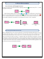
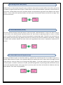
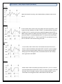
Out 00
While out mode is 0 (zero), don’t observed any output at Out-1 and
Out-2.
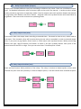
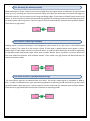
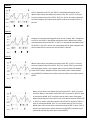
Out 01
In this mode; when count value rises above the level of the SET-1, OUT1 gives the out (so Relay-1 is ON). If TOUT-1 is selected (Time of Relay1) HOLD, OUT-1 is active until count value falls bottom level of SET-1.
When count value rises above the level of the SET-2, OUT-2 is give the
out and If TOUT-2 is selected HOLD, OUT-2 is active until count value
falls bottom level of SET-2. TOUT-1 and TOUT-2 are selected as term,
OUT-1 and OUT-2 will active during this time.
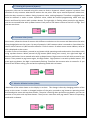
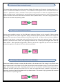
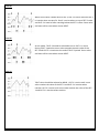
Out 02
In this mode, when count value rises above the level of the SeT-1,
OUT-1 is active and above the level of SET-2, OUT-2 is active. Relays
will be active even goes down below the set values without RESET.
Relays give outs during this time, if entered times for outs. Relays
don’t give outs until RESET.
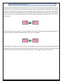
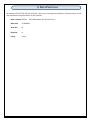
Out 03
When count value rises above the level of the SeT-1, OUT-1 is active
and rises above level of the SET-2, OUT-2 is active. So count value will
be fixed. Even if encoder’s pulse is at device without RESET, count
value does not change but count value and outs will be reset.
- 12 -