1
COMMANDfleet
1/14/15
Copyright © 2007 - 2015 Command Alkon Incorporated and/or its affiliates. All rights reserved.
The contents of this document are for informational purposes only and are subject to change without notice.
Command Alkon Incorporated (“CAI”) may, without notice, modify its products in a way that affects the
information contained in this publication.
CAI HEREBY DISCLAIMS ALL REPRESENTATIONS OR WARRANTIES EITHER EXPRESSED OR
IMPLIED, INCLUDING WITHOUT LIMITATION ANY IMPLIED WARRANTY OF
MERCHANTABILITY, TITLE, NON-INFRINGEMENT, OR FITNESS FOR A PARTICULAR
PURPOSE. In no event will CAI be liable for any direct, indirect, or consequential damages arising out of the
use of, inability to use, or implementation of any information contained in this publication, even if CAI has been
advised of the possibility of such damages, or for any claim by any other party.
The information contained herein is subject to change without notice and may contain inaccuracies or errors.
CAI assumes no responsibility for any errors that may appear in this document. This publication is intended
only for the direct benefit of authorized users of CAI products. This publication may not be used for any
purposes other than those for which it is provided, and it is subject to the terms of the applicable software license
or subscription agreement. This publication and the information disclosed herein is the property of CAI, and,
except for rights granted by written consent, may not be disclosed, disseminated, or duplicated in whole or in
part.
Command Alkon Incorporated
1800 International Park Drive, Suite 400
Birmingham, AL 35243-4232
(205) 879-3282
5168 Blazer Parkway
Dublin, OH 43017-1339
(614) 799-6650
www.commandalkon.com
COMMANDseries (and the names of its components, such as COMMANDconcrete and
COMMANDnetwork), Spectrum, Eagle, and COMMANDbatch are trademarks of Command Alkon
Incorporated. All rights reserved.
Microsoft and Windows are trademarks of Microsoft Corporation. Other names may be trademarks of their
respective owners.
Welcome to COMMANDfleet
........................................................... 4
COMMANDfleet Is Your Fleet Signaling Solution ..........................................4
What does COMMANDfleet do? ..............................................................4
The COMMANDfleet User Manual ...............................................................4
Included Sections ................................................................................4
Before Installing COMMANDfleet
.................................................... 6
COMMANDseries Licensing and Modules .....................................................6
COMMANDfleet Hardware and Software Requirements .................................7
Hardware Requirements .......................................................................7
Software Requirements ........................................................................7
The Components of COMMANDfleet ...........................................................8
COMMANDseries Integrated Server (CSIS) ..............................................8
Protocol Manager (PM) .....................................................................8
Business Logic Server (BLS) .............................................................8
COMMANDnetwork Client (CNClient) ..................................................9
Microsoft Message Queuing (MSMQ) ..................................................9
Installing COMMANDfleet
............................................................. 10
Preliminary Microsoft Installations and COMMANDseries Settings ................ 10
Microsoft Message Queues (MSMQ) ...................................................... 10
Microsoft .NET Framework .................................................................. 12
COMMANDseries Signaling Unit Configuration ........................................ 14
Using the COMMANDfleet Installation Wizard ............................................ 17
Initial Installation of COMMANDfleet ..................................................... 17
The CSIS Installation Structure ............................................................ 18
Upgrading COMMANDfleet ................................................................... 18
Integration with COMMANDseries ............................................................ 18
Initial Integration with COMMANDseries ................................................ 18
After a COMMANDseries Upgrade ......................................................... 19
Configuring the Command Alkon Configuration Console ............................. 19
Adding and Configuring the CSIS Components ....................................... 20
CNClient ...................................................................................... 20
Adding and Configuring a Signaling BLS ........................................... 23
Adding a COMMANDsignal PM ......................................................... 32
Adding a New Interface for a Third Party Signaling Vendor .................. 34
Queues Setup ................................................................................... 37
Queue Monitor .............................................................................. 41
Configuring the COMMANDfleet Desktop ............................................... 42
Save Your Settings ........................................................................ 45
Starting and/or Removing Components ................................................. 46
The CSIS Protocol Manager
.......................................................... 48
How to Start and Configure the CSIS PM
................................................. 48
1
Create a PM Desktop Icon ................................................................... 48
Starting the PM for the First Time ........................................................ 50
Configuring the PM from the System Menu ............................................ 51
Configure RICs ............................................................................. 52
Outgoing Message Options ............................................................. 53
Auto Clear Screens On New Day ...................................................... 53
New Truck Number Registration ...................................................... 54
Diagnostic Log .............................................................................. 54
Host Options ................................................................................ 56
Status Key Lockout ....................................................................... 56
Remote VSC2 Settings ................................................................... 57
Truck Load Capacity ...................................................................... 60
Using the CSIS PM ................................................................................ 60
The Vehicle Tracking Pane ................................................................... 61
The Incoming Status Pane .................................................................. 61
The Outgoing Messages Pane .............................................................. 62
Message Menu Options ....................................................................... 62
Send Text or LED Message ............................................................. 62
Resend All Messages Now ............................................................... 62
Auto Poll Options .......................................................................... 63
View Menu Options ............................................................................ 63
View Communications .................................................................... 63
Using the COMMANDfleet Dispatch Desktop
................................. 68
Launching the Dispatch Desktop ............................................................. 68
Toolbar Menu Options ........................................................................... 68
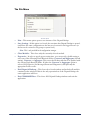
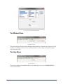
The File Menu .................................................................................... 69
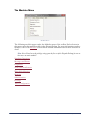
The Modules Menu ............................................................................. 70
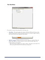
The View Menu .................................................................................. 71
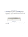
The Format Menu .............................................................................. 72
The Window Menu ............................................................................. 73
The Help Menu .................................................................................. 73
Dispatch Desktop Basics ........................................................................ 75
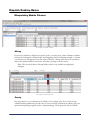
Manipulating Module Columns ............................................................. 75
Moving ........................................................................................ 75
Sorting ........................................................................................ 75
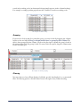
Grouping ...................................................................................... 76
Filtering ....................................................................................... 76
Right-Click Context Menus .............................................................. 77
Modules .............................................................................................. 80
Signaling Operations .......................................................................... 80
Messages and Events ......................................................................... 81
Messages Pane ............................................................................. 81
Events Pane ................................................................................. 82
2
Error Log Pane .............................................................................. 82
Diagnostics ....................................................................................... 83
Favorites Pane .............................................................................. 84
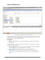
Alerts and Notifications ....................................................................... 85
Alerts Tab .................................................................................... 85
Configuration Tab .......................................................................... 86
Alert Messages ............................................................................. 87
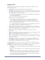
Water Added Inquiry .......................................................................... 87
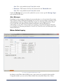
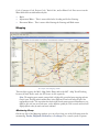
Mapping ........................................................................................... 88
Monitoring Group .......................................................................... 88
Display Options Group ................................................................... 89
Administration ................................................................................... 90
Privilege ........................................................................................... 91
Privileges for Normal Operations ..................................................... 92
Optional Privileges ......................................................................... 93
Administrator Privileges ................................................................. 93
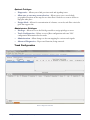
Truck Configuration ............................................................................ 93
Truck Configuration Fields .............................................................. 94
Truck Configuration Context Menu ................................................... 95
JBUS PID Table ............................................................................. 96
Common Procedures for the Truck Configuration Module ..................... 97
Appendix
...................................................................................... 99
Product Integration ............................................................................... 99
The BLS Signaling Tab ........................................................................ 99
Optimization ................................................................................. 99
EDX .......................................................................................... 100
COMMANDbatch .......................................................................... 101
3
Welcome to COMMANDfleet
COMMANDfleet is a vehicle data collection tool that provides an integrated and
centralized fleet communication center allowing for simplified diagnostics of one or more
vehicles. COMMANDfleet is based on a reliable, remotely serviceable, scalable platform to
support future modules and vehicle data.
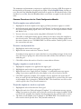
COMMANDfleet Is Your Fleet Signaling Solution
What does COMMANDfleet do?
•
•
•
•
•
Delivers real-time and historical vehicle event and location information to the
appropriate managers.
Provides real-time and short-term historical drill-into support as a dispatch tool.
Provides a centralized fleet communication center to one or more vehicles based on
business scenarios.
Delivers real-time status and message events to dispatchers and other managers.
Collects vehicle on-board data including GPS and various electronic sensors, and
provides a flexible data mining and presentation for both dispatchers and managers.
The COMMANDfleet User Manual
This user guide contains helpful information regarding the initial installation and
subsequent upgrades of COMMANDfleet, the use COMMANDfleet for your business
operations, and the integration of COMMANDfleet to other Command Alkon products.
Included Sections
•
•
•
•
4
Before Installing COMMANDfleet - This section contains general information
regarding the necessary hardware and software to run COMMANDfleet successfully.
Whether you are considering the installation of COMMANDfleet for the first time or
you are upgrading your current version, you should consult this section of the manual
to ensure that all of your components are compatible.
Installing COMMANDfleet - This section outlines the steps required to install the
COMMANDfleet package in order to interface with trucks using Command Alkon’s
VSC (COMMANDsignal), TrackIt, or any other 3rd party signaling vendor. It also
details the upgrade procedures for COMMANDfleet and its COMMANDseries
interface.
The CSIS Protocol Manager - This section only applies to those using a
COMMANDsignal PM and deals with the initial configuration as well as the general
use of the CSIS PM.
Using the COMMANDfleet Dispatch Desktop - Note that this section of the manual is
aimed at two types of users:
Welcome to COMMANDfleet
Normal user - This is a person who uses the program on a daily basis.
Configuration manager - This person sets up the screen layout using one or more
monitors, including the window positions, window sizes, columns displayed,
widths, and so on. Once the configuration has been set and saved, it can be “locked”
so other users can’t change the layout. This promotes a level of consistency among
the user group.
Appendix - This section provides reference information related to the integration of
COMMANDfleet to other Command Alkon products including
COMMANDoptimize and COMMANDbatch.
•
Welcome to COMMANDfleet
5
Before Installing
COMMANDfleet
Topics in this section:
COMMANDseries Licensing and Modules
COMMANDfleet Hardware and Software Requirements
The Components of COMMANDfleet
COMMANDseries Licensing and Modules
The following licenses or modules are needed in COMMANDseries before beginning the installation of
the CSIS components:
•
•
•
•
•
MS (Mobile Signaling): Provides the signaling interface between COMMANDseries
and COMMANDsignal/COMMANDfleet. Prerequisite modules for MS are OE
(Order Entry) and TT (Truck Tracking).
AS (Auto Statusing): Sends trip packets to trucks in order to identify the Plant and
Job Site coordinates.
MO (Map Order Entry): Control + I functionality to capture GPS coordinates for
Job Sites.
FL (COMMANDfleet): This allows COMMANDfleet to be opened within
COMMANDseries and/or COMMANDtrack.
Signaling Unit: COMMANDsignal with CSIS (27) for COMMANDsignal systems
or 3rd party ENH (26) for 3rd party systems. One Signaling Unit is required for each
signaling interface in the event that there may be multiple interfaces.
For more information on configuring a signaling unit, see Preliminary Microsoft
Installations and COMMANDseries Settings.
The following licenses or modules are optional:
•
•
•
6
MT (Map Truck Tracking): Provides Truck location capability from
COMMANDtrack.
WA (Water Added): Requires the trucks to have water meters and JBUS data
installed.
ST (Snail Trail): Delivery cycles can be displayed for current day and historical
lookups.
Before Installing COMMANDfleet
COMMANDfleet Hardware and Software Requirements
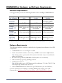
Hardware Requirements
It is suggested that you have the following hardware before installing COMMANDfleet:
No. of Trucks
0-50
1 P4 2.0 GHZ
50-200
Dual Core 2.4 GHZ
2.0 GB
3.0 GB
200-500
Dual Xenon Hyperthreaded 2.4 GHX
3.0 GB
Storage
System (OS/
Local)
1x40 GB SATA or
EIDE 7200/10,000
RPM
RAID 1 2x40 GB
SATA or SCSI 7200/
10,000 RPM
RAID 1 2x40 GB
SATA or SCSI 7200/
10,000 RPM
Storage
System (DB
Sizing)
Update DB storage
for new requirements
Update DB storage
Update DB storage
for new requirements for new requirements
Windows 2003/2008/
2008 R2/2012 Server
SP1
Windows 2003/2008/
2008 R2/2012 Server
SP1
Processor
Memory
Operating
System
Windows 2003/2008/
2008 R2/2012 Server
SP1
Note: For 500+ trucks, please refer to the Command Alkon Technical team for COMMANDfleet server requirements.
Software Requirements
The following should be installed or enabled before beginning the installation of the CSIS
components:
•
•
COMMANDseries v5.54 and higher or CS08
Oracle client/ Oracle database connectivity or ODBC connection for SQL Database
•
•
•
Note: 64-bit machines require both the 32-bit and the 64-bit Oracle clients to be installed with a
path to the 32-bit client.
Remote Desktop enabled (VMWARE or PCAnywhere not recommend)
Microsoft Message Queuing (MSMQ) enabled
.NET Framework 3.5.1
•
Note: 64-bit machines require .NET Framework 4.0 in addition to 3.5.1. Also, CSIS 2.5.5 and
earlier require only a minimum of .NET 2.0.1.
One COMMANDnetwork client license per CSIS instance (for the CNClient)
For more information on enabling or installing MSMQ and verifying your .NET
Framework, see Preliminary Microsoft Installations and COMMANDseries Settings.
Before Installing COMMANDfleet
7
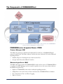
The Components of COMMANDfleet
There are three main components of COMMANDfleet including a digital or analog interface, the COMMANDfleet
Desktop and the COMMANDseries Integrated Server.
COMMANDseries Integrated Server (CSIS)
Protocol Manager (PM)
The PM is the gateway for all inbound/outbound fleet traffic in a COMMANDsignal
system. It replaces the VSC Base software, but has the same look and feel as the traditional
signaling interface.
•
•
Handles all protocol management to and from the fleet.
Accepts Load Events from Batch Consoles.
Business Logic Server (BLS)
The BLS is the logic portion of COMMANDfleet and is where most of COMMANDfleet
is configured. A BLS Manager can be created for quick access to the service that resides in
the Windows System Tray.
•
•
•
•
8
Replaces COMMANDcomm in the traditional signaling interface.
Manipulates, stores and retrieves data to and from the COMMANDseries database.
Key component in Trace and Error Logging.
Runs as a service.
Before Installing COMMANDfleet
COMMANDnetwork Client (CNClient)
The CNClient is the COMMANDnetwork Client for COMMANDfleet. A CNClient
Manager can be created for quick access to the service that resides in the Windows System
Tray.
•
•
Communicates to the COMMANDnetwork Server.
Runs as a service.
Microsoft Message Queuing (MSMQ)
This replaces the serial cable in the traditional signaling interface and enables messages to be
sent to and from the PM, BLS and CNClient services.
Before Installing COMMANDfleet
9
Installing COMMANDfleet
Before beginning the installation, it is suggested that you review the Before Installing
COMMANDfleet section of this manual so that you are familiar with the hardware and
software requirements.
Topics in this section:
Preliminary Microsoft Installations and COMMANDseries Settings
Using the COMMANDfleet Installation Wizard
Integration with COMMANDseries
Configuring the Command Alkon Configuration Console
Preliminary Microsoft Installations and COMMANDseries
Settings
Microsoft Message Queues (MSMQ)
Verify that MSMQ’s are installed on the server that will be running the CSIS components
by using the following process relative to your operating system.
For Windows 2003:
1.
2.
3.
4.
10
Select {Start > Settings > Control Panel}.
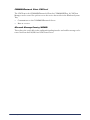
For Windows 2003, open Administrative Tools followed by Computer
Management.
Expand the Services and Applications node by clicking on it.
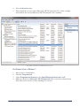
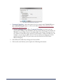
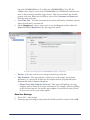
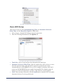
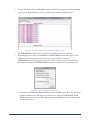
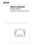
If MSMQ is already installed there will be a Message Queuing entry:
Installing COMMANDfleet
You will know that the MSMQ has been installed if, when on this screen, the Message Queuing entry is present.
5.
6.
If MSMQ is not installed, continue with the following steps.
From the Windows Control Panel {Start > Settings > Control Panel}, select Add or
Remove Programs.
7. On the left side, click Add/Remove Windows Components.
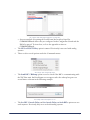
8. Select the Message Queuing line and click on the Details button.
9. Select the Common checkbox and deselect both the Active Directory Integration
and Triggers checkboxes. Common is the only checkbox that should be selected.
10. Click OK to close the Message Queuing dialog box. The Windows Components Wizard
should now have Message Queuing selected.
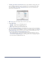
11. Click Next to finish installing the MSMQ. The Configuring Components dialog box
appears so you can view the installation progress. Two services (mqsvc and mqtgsvc)
will default to starting automatically; do not change this.
12. Click Finish to close the wizard.
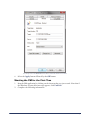
For Windows Vista or Windows 7:
1.
2.
3.
Select {Start > Control Panel}.
Click the Programs link.
Under Programs and Features, select Turn Windows features on or off.
Installing COMMANDfleet
11
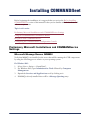
4.
5.
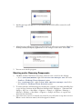
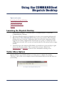
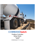
Expand Microsoft Message Queue (MSMQ) Server.
Make sure the box for Microsoft Message Queue (MSMQ) Server Core is selected
as shown. Note that you do not have to have anything else selected.
An example of the Microsoft Message Queue (MSMQ) Server entry.
Microsoft .NET Framework
Verify that you have Microsoft .NET Framework 3.5.1 installed on the server that will be
running the CSIS components by using the following process relative to your operating
system.
For Windows 2003:
1.
2.
3.
12
Select {Start > Settings > Control Panel}.
Open Administrative Tools followed by Computer Management.
Expand the Services and Applications node by clicking on it.
Installing COMMANDfleet
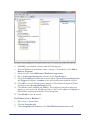
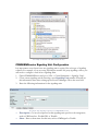
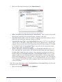
4.
5.
Select the Services entry.
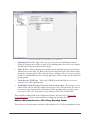
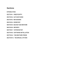
There should be a service named Microsoft .NET Framework v3.5.1. In the example
shown below, the user has Microsoft .NET Framework v4.0.3 installed.
An example of the Microsoft .NET Framework service.
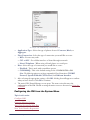
For Windows Vista or Windows 7:
1.
2.
3.
4.
Select {Start > Control Panel}.
Click the Programs link.
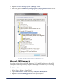
Under Programs and Features, select Turn Windows features on or off.
Make sure the box for Microsoft .NET Framework 3.5.1 is selected as shown below.
Note that you do not have to have anything else selected.
Installing COMMANDfleet
13
An example of the Microsoft .NET Framework entry.
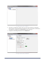
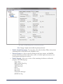
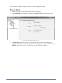
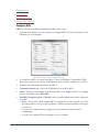
COMMANDseries Signaling Unit Configuration
It is important to note that at least one signaling unit is required for each type of signaling
solution. For example, if you are using TrackIt plus another 3rd party signaling vendor, you
will need to configure a total of two signaling units.
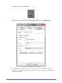
1.
2.
3.
Open COMMANDseries and go to {Files > General Information > Signaling Units}.
Create a new signaling unit by entering a new Signaling Unit number. You will use
this information later when setting up the Protocol Manager. Tab to the next field.
Enter the following information for the signaling unit:
An example of the Signaling Units form in COMMANDseries V2.
•
•
14
Description - Create a description for this signaling unit specific to the integration,
such as CSIS Interface, TrackIt GPS, or Trimble.
Short - Enter a short name for this unit, such as CMDsignal or TrackIt.
Installing COMMANDfleet
•
•
•
•
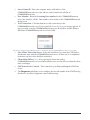
4.
Unit Type - Select a unit type based on your COMMANDseries configuration.
COMMANDsignal - Select this option for COMMANDseries version 5.56 and
earlier, regardless of your configuration.
COMMANDsignal with CSIS- Select this option for COMMANDseries version
5.57 and later if you are using a COMMANDsignal configuration.
Third Party ENH - Select this option for COMMANDseries version 5.56 and
later if you are using TrackIt, Trimble, etc.
Manager Number - This can be any number that is specific to this signaling unit and
must be unused by any other comm manager. You will use this information later when
setting up the Business Logic Server.
Port Name - This is an unused COM port that does not exist, however it is required
that you have a value entered.
Attack Delays - This is an old field that was used in conjunction with analog systems.
It may be left blank.
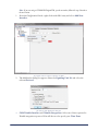
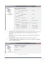
The Options tab should be similar to the following:
An example of the Options tab for Signaling Unit 90.
5.
The Default button should be used to populate the messages under the Incoming
and Outgoing tabs.
Installing COMMANDfleet
15
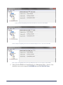
An example of the Incoming tab for Signaling Unit 90.
An example of the Outgoing tab for Signaling Unit 90.
6.
16
Under the Statuses tab, the default statuses are populated as below but can be
customized to match signaling interfaces:
Installing COMMANDfleet
An example of the Statuses tab for Signaling Unit 90.
7.
Save the new signaling unit by pressing F2.
Using the COMMANDfleet Installation Wizard
Initial Installation of COMMANDfleet
The COMMANDfleet install package has all the files and applications needed to install the
COMMANDfleet product suite. It is an integrated installation kit that ties together all the
products required for a COMMANDfleet setup. This procedure is for a new installation; if
you already have a COMMANDfleet installation, follow the instructions below in
Upgrading COMMANDfleet.
1.
2.
3.
4.
5.
6.
Using Command Alkon’s FTP server, copy the COMMANDfleet install package to
the local machine that will act as the CSIS server.
Note: The installation package can be made available on a CD upon request.
The COMMANDfleet Setup dialog box appears.
Select CSIS and click Next.
The Destination Folder dialog box appears. Click Next to accept the default destination
folder C:\CSIS\. Browse to the appropriate drive letter if it is not C:.
After installing the necessary files, the InstallShield Wizard Complete dialog box appears.
Click Finish to complete the installation.
After a few seconds, the Command Alkon Configuration Console will appear so you can set
up the CSIS components. These are outlined in the Configuring the Command Alkon
Configuration Console section.
Installing COMMANDfleet
17
The CSIS Installation Structure
The CSIS components directory structure is similar to the following illustration. The disk
drive may vary.
C:\CSIS
\BLS
\BLSxxx
\CNClient
\Configuration
\PM
\PMxx
\QueueMonitor
Notes:
•
•
•
The base BLS and PM folders are not the production folders. During the configuration process,
additional BLS and PM folders are created.
The \BLS folder is for the BLS executable only. BLSxxx is a separate working folder for the
instance of BLS that is running for the configuration. For example, BLS600 represents Manager
Number 600 for the BLS.
The \PM folder is for the PM executable only. PMxx is a separate working folder for the instance
of PM that is running for the configuration. For example, PM20 represents Signal Unit number 20
for the PM.
Upgrading COMMANDfleet
Before upgrading an older version of COMMANDfleet, you should make a copy of the
current CSIS directory and rename it, such as CSIS_old. This is to protect your
COMMANDfleet data in case anything goes wrong during the upgrade.
1.
2.
3.
Once you have made a copy of your CSIS directory, upgrade COMMANDfleet by
following the steps detailed in the Initial Installation of COMMANDfleet.
Press the Finish button on the installer to launch the Configuration Console.
Verify and change any options for this installation. The old configuration files should be
upgraded automatically. Some options may no longer be supported while others will be
added with defaults.
Integration with COMMANDseries
Initial Integration with COMMANDseries
In order to open COMMANDfleet from the COMMANDconcrete or
COMMANDaggregate applications, you must copy the COMMANDfleet folder to a
location inside the CMDseries folder.
18
Installing COMMANDfleet
For COMMANDfleet to properly integrate with COMMANDseries, certain licenses must
be set up (COMMANDseries Licensing and Modules) and the COMMANDseries
initialization file must point to the COMMANDfleet installation. The initialization file
cmdserie.asn is located in the Clients folder. The [logicals] section of this file must have
a line pointing to the location of the COMMANDfleet installation, similar to the following:
[logicals]
Command_Fleet=C:\CMDseries\COMMANDfleet\Dispatchertools.exe
After a COMMANDseries Upgrade
If you are running COMMANDfleet, the following is required to maintain the current
configuration after a COMMANDseries upgrade:
1.
2.
3.
Copy the COMMANDfleet folder to a location inside the CMDseries folder.
Proceed with the normal COMMANDseries upgrade procedure.
After upgrading, move the copied COMMANDfleet folder back into the CMDSERIE
folder and ensure the name of the folder is COMMANDfleet.
Note: Version 5 of COMMANDseries can only run up to COMMANDfleet 2.12.
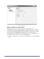
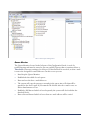
Configuring the Command Alkon Configuration Console
This console is a centralized configuration and management location for the CNClient,
BLS, PM, and each of their Queues. The next few sections explain how to create, configure
and start each of the COMMANDfleet components from within the Configuration
Console.
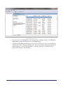
Adding and Configuring the CSIS Components
Configuring the COMMANDfleet Desktop
Starting and/or Removing Components
Installing COMMANDfleet
19
An example of the Command Alkon Configuration Console.
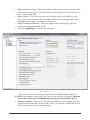
Adding and Configuring the CSIS Components
CNClient
Since COMMANDfleet receives messages from COMMANDseries via
COMMANDnetwork, the first step is to connect to the COMMANDnetwork network.
Note: Adding and configuring the CNClient to the network uses or replaces one network user in the
COMMANDseries license.
Once connected, follow these steps:
1.
20
From the Configuration Console, select CSIS. Right-click on it and select Add
CNClient.
Installing COMMANDfleet
An example of how to add a new CNClient.
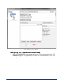
2.
3.
An instance of CNClient is added. This step registers the CNClient as a Windows
Service named Command Network Client Service. Click on the newly created instance
of CNClient to configure the COMMANDnetwork connection.
Complete the following information for the General tab:
An example of the General tab of the CNClient.
Installing COMMANDfleet
21
•
•
•
Server Name/IP - Enter the computer name or IP address of the
COMMANDnetwork server (the address can be found in the title bar of
COMMANDnetwork).
Port Number - Enter the Listening Port number for the COMMANDnetwork
server (the default is 12100). This number can be found on the COMMANDnetwork
Setup screen.
Test Connection - Click this button to verify connectivity to the
COMMANDnetwork server. If successful, the Connection Successful message appears. If
not successful, verify the COMMANDnetwork server IP and Port, and the ability to
PING the COMMANDnetwork server from CSIS.
This message will appear if the CNClient is able to communicate with the COMMANDnetwork Server successfully.
•
•
•
4.
22
Sync Client Time with Server - Select this checkbox if you want the CNClient to
synchronize time with the COMMANDnetwork server. If time sync is accomplished
in another way, leave this checkbox unchecked.
Client Hour Offset (+/-) - If are syncing the client time with a
COMMANDnetwork server in a different time zone, use this offset to adjust the client
time accordingly.
CNClient Service Control - These buttons let you Start and Stop the CNClient
service.
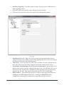
The Diagnostics tab allows you to configure the size and number of the CNClient log
files that are needed for diagnostics and troubleshooting.
Installing COMMANDfleet
An example of the Diagnostics tab.
Adding and Configuring a Signaling BLS
With the CNClient ready to pass messages between COMMANDfleet and
COMMANDnetwork, we now need to configure the Business Logic Server. The BLS
processes messages between COMMANDnetwork and other business interfaces. There are
two different options (Signaling BLS or Optimization BLS) for creating the logic module
and the application of COMMANDfleet will determine how you setup it up. It is
important to note that you may only have 1 BLS instance per server. Unless Optimization is
being implemented, you will need to configure a Signaling BLS.
1.
From the Configuration Console, right click on CNClient and select Add Signaling
BLS.
Installing COMMANDfleet
23
An example of how to add a signaling BLS.
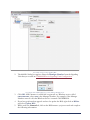
2.
The Add BLS dialog box appears. Enter the Manager Number from the Signaling
Unit that you created in COMMANDseries Signaling Unit Configuration.
An example of the Add BLS dialog box, with a Manager Number of 90.
3.
4.
5.
24
Click OK. A BLS instance is added and is registered as a Windows service called
CACSISBLSxxx, where xxx is the Manager Number. For example, if the Manager
Number entered is 90, that Windows Service is named CACSISBLS90.
If you have performed an upgrade and need to update the BLS, right click on BLSxx
and select Update BLS.
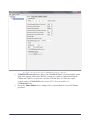
While under the General tab, click on the BLS instance you just created and complete
the following information:
Installing COMMANDfleet
An example of the General tab of the BLS.
•
•
6.
COMMANDseries Version - Enter your COMMANDseries version number in this
field. Note that the CS06 and CS08 2.x versions are considered 6.0.0.0 and that the
CSPlus and CS08 3.x versions are considered 7.0.0.0. Prior to CS06, the 4-place
version, such as COMMANDseries version 5.57.9.19, was used for v5
COMMANDseries.
BLS Service Control - These buttons let you Start and Stop the BLS service;
however, it is strongly recommended that you do not use these buttons unless under the
advisement of Command Alkon Personnel.
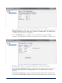
Under the Database tab, complete the following information:
An example of the Database tab for a BLS using an Oracle Database Type
Installing COMMANDfleet
25
.
An example of the Database tab for a BLS using a SQL Server Database Type
•
•
•
•
26
Database Type - Select the appropriate database from this drop-down list.
Server/Username/Password - Enter your database connection information (if
unknown, you can get these from the COMMANDseries ASN file).
Test Connection - Click on this button to test your connection to the database
engine. If successful, the Connection Successful dialog box appears.
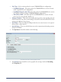
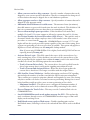
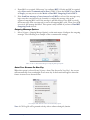
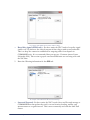
Update Database - Click on this button if the database needs updating (this may take
up to an hour). A text box directly below the controls will show the progress of the
update. When finished, a log file appears as shown below. If the database is current, a
message appears stating Database already has current schema.
Installing COMMANDfleet
An example of using the Update Database button.
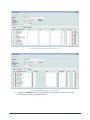
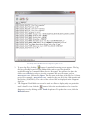
•
Show Tables - Click on this button to open a SQL log which lists current tables and
the database architecture.
An example of the Display SQL Results window that appears after using the Show Tables button.
•
Existing Upgrade Logs - The drop-down field allows you to view previous upgrade
logs. The logs are listed by COMMANDfleet version and the date of the update.
Installing COMMANDfleet
27
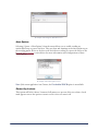
7.
The Trace Logging tab allows for data to be taken for troubleshooting purposes. You
may select Terse (short) or Verbose (long) depending on the level of detail you want to
record. It is not necessary to select the checkboxes at this moment.
An example of the Trace Logging tab for the BLS.
•
8.
28
While under the Trace Logging tab, it is required that you have Enable Trace
Queue and Process Messages selected. Optional selections include Write Sql
Statements to Service Log, Detailed SQL Statement Logging, and Compress
Xml in the Service Log.
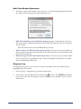
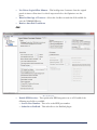
Under the Maintenance tab, complete the following information:
Installing COMMANDfleet
An example of enabled purging with a record retention of 30 days.
•
•
•
Note: Purging is highly recommended for optimal performance.
Enable scheduled purging - To purge data, select this checkbox. When selected, the
remaining fields on this tab become available for use.
Execute purges at - Select a time by clicking on the hour, minute, and AM/PM
portion of the time and then either enter a time or click the up/down arrows (or use
your keyboard up/down arrow keys).
Enable Purging - Select one or more of the remaining checkboxes to allow the
purging of the following logs:
- Purge Task
- Water Added Event Log
- Transaction Log
- GPS Event Log
- Alerts
- Trace Log
- Error Log
- Transaction Messages
- JBUS Even Log
Installing COMMANDfleet
29
•
•
•
9.
Keep records for x days - This is the number of days to keep the alert messages. This
will determine how long you will retain historical data and depends on the how you set
it for each particular field.
Alert Criteria - This is the refresh period (in milliseconds) for the BLS to get the
latest criteria. The minimum value is 600000 (10 minutes) and the maximum value is
86400000 (which equals 1,440 minutes or 24 hours).
Purge Command Timeout - This is the length of time that purging is allowed
starting at the Execute purges at time.
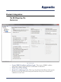
Under the Signaling tab, complete the following:
BLS: Signaling Tab
Note: For more information regarding the Optimization, COMMANDbatch, EDX and
MOBILEconnect Integration sections, please refer to their respective section of the appendix. Do not use
these sections unless it has been implemented as part of your current business process.
•
30
Manager Number - This refers to the Manager Number for the Signaling Unit and
defaults from the BLS setup. If this number needs to be changed, the BLS and all of its
PM children must be deleted and added again.
Installing COMMANDfleet
Business Rules
•
•
•
•
•
•
•
•
•
•
Allow concrete trucks to skip x statuses - Specify a number of statuses that can be
skipped by your concrete trucks. It defaults to 1 but it is recommended to change it to 2
to allow statuses that may be skipped due to truck hardware problems.
Allow aggregate trucks to skip x statuses - Specify a number of statuses that can be
skipped by your aggregate trucks.
Maximum allowed minutes for valid status - The amount of time (in minutes)
that valid statuses are processed from the time the truck is ticketed. This defaults to 240
but it is recommended to increase that value to accommodate pre-ticketing.
Do not allow multiple pours per ticket - If this checkbox is left unchecked,
multiple Wash and To Plant time stamps are allowed to capture the total On Job time.
Get Unique Number by Stored Procedure (SQL Server) - This option is used to
determine whether the unique employee time record number comes from a stored
procedure or comes from the NUNQ table. COMMANDseries version 5.57.7.11 and
higher will use the stored procedure option regardless of the state of this setting. Prior
versions can optionally use the store procedure if available. This option only applies to
SQLServer. Oracle will always use the NUNQ table lookup method.
Note: If you are using COMMANDfleet 2.16 or higher, Oracle and SQL 2012 will now use
sequencing instead of the NUNQ table.
Activate Driver Login - This field controls the source of the current driver for a
truck entering into service. If this checkbox is not selected, the current driver of the
truck is populated by the assigned driver within the TRUC record for the truck. If this
checkbox is selected, the following options become available:
Truck's Current Driver Only - The current driver of a truck is pulled from the
driver login message that is sent from the signaling unit within the truck.
Truck's Current and Assigned Driver - When the driver login updates the
current driver, that driver is no longer overridden with the assigned driver.
GPS Satellite Count Validation - Satellite information sent from a VSC signaling
unit includes the number of satellites on which the GPS location was triangulated.
Three satellites are required to pinpoint a latitude and longitude. In some cases, having
only three satellites can lead to occasional erroneous positioning. Having four or more
locked satellites usually provides a more accurate positioning of the vehicle.
Minimum Satellites - This allows you to configure the minimum number of
satellites that can be used to obtain an accurate GPS positioning for the vehicle.
Do not Change the Truck Color - This may override Condition/Task codes in
COMMANDseries.
Send COMMANDnetwork truck update message for GPS - This updates the
truck coordinates through a series of COMMANDnetwork messages so that it will
display on the tracking screen.
EndUnload status equals to Wash status - Trimble signaling units send an
EndUnload status; if this flag is selected, the end unload time will be used as the Wash
time.
Installing COMMANDfleet
31
•
•
•
•
EndLoad status equals to Load Status - This is used when the BeginLoad status is
missing or invalid.
Ignore Blank Truck Flags - This will ignore blank truck flags.
Allow Overnight Pours - This allows dispatch to continue deliveries without
interruption past midnight and allows billing on the day the pour started instead of the
next business day.
Water Added Events Item Code - This field identifies the COMMANDseries item
that is to be used to record water added events for billing purposes.
Adding a COMMANDsignal PM
In this section, the Protocol Manager (PM) will be created if you use COMMANDsignal.
Each BLS must have its own PM to manage traffic.
1.
From the Configuration Console, right-click on the BLS entry and select Add New
Interface.
An example of how to add a new interface to a BLS.
2.
32
The Add Interface dialog box appears. Enter the Signaling Unit Code and select the
relevant Protocol.
Installing COMMANDfleet
An example of the Add Interface dialog box.
•
3.
4.
Command Signaling - Select this option if you are using both COMMANDseries
and COMMANDsignal. If not, see the section titled Adding a New Interface for a
Third Party Signaling Vendor.
Protocol Manager Port - When Command Signaling is selected, you can
specify which UDP port the PM binds (listens) to when starting up. By default, the
PM binds to port 2100 to listen to incoming traffic from trucks. Now you can run
two instances of the PM on the same host, each bound to a different UDP port. For
example, you can run two PMs (one for Concrete and one for Aggregate) on the
same host with one BLS. The port value entered in this field is stored in the
Windows Registry.
Click OK and the PM entry will appear below the BLS.
Click on the new PM entry and complete the following information:
Installing COMMANDfleet
33
An example of the PM settings including a Code 16 (GPS Poll).
•
•
•
•
Signaling Unit Code - This is the code you entered on the Add Interface form. It
cannot be changed once a PM is created. If the signaling unit code needs to be changed,
the PM must be deleted and then added again.
Time To Live - This is the time (in minutes) that an inbound message sent from the
PM will exist on the PM_TO_BLS queue before being discarded to the Transactional
dead-letter messages queue. Once discarded, these messages will never be processed by
the BLS or found within the Fleet desktop application. These messages must be checked and
purged regularly.
Truck Receive UDP Port - This is the UDP/IP port that the PM uses to receive
messages from VSC signaling units.
Outbound Coded Messages (forced as non-text messages) - If a message code is
added to this text box, then the outbound message for the code will always be sent as a
non-text message (found in the outbound tab of the signaling unit), even if message
text exists for the code. This option is frequently used for code 16 (GPS Poll).
This concludes adding a PM to the Configuration Console. You may refer to The CSIS
Protocol Manager section for information on configuring and using the PM.
Adding a New Interface for a Third Party Signaling Vendor
This section covers information needed to add an interface for a 3rd party signaling vendor.
34
Installing COMMANDfleet
1.
Note: If you are using a COMMANDsignal PM, you do not need to follow this step. Proceed to
the next section.
From the Configuration Console, right-click on the BLS entry and select Add New
Interface.
An example of how to add a new interface to a BLS.
2.
The Add Interface dialog box appears. Enter the Signaling Unit No and select the
relevant Protocol.
An example of the Add Interface dialog box.
•
CSIS/Trimble Interface and Trimble Integration- Select one of these options for
Trimble integration a protocol. You will also need to specify your Time Zone.
Installing COMMANDfleet
35
•
3.
4.
3rd Party Signaling - Select this option if using a 3rd party generic XML interface
with a signaling vendor.
Click OK and the new interface entry will appear below the BLS.
Click on the new interface entry and complete the following information:
PM Settings
•
•
•
•
36
Signaling Unit Code - This is the code you entered on the Add Interface form. It
cannot be changed once a PM is created. If the signaling unit code needs to be changed,
the PM must be deleted and then added again.
Time Zone - This is the time zone where the truck fleet is located. It defaults as the
time zone of the server but can be changed to match the location of the trucks.
Outbound Coded Messages (forced as non-text messages) - If a message code is
added to this text box, then the outbound message for the code will always be sent as a
non-text message (found in the outbound tab of the signaling unit), even if message
text exists for the code. This option is frequently used for code 16 (GPS Poll).
Web Interface - This allows you to properly configure and deploy the EDS Service
and Plugins and EDX Plugins\CSIS when: creating new BLS/EDX Interface
configuration, changing the configuration or upgrading the Fleet software.
Installing COMMANDfleet
This concludes adding a 3rd party interface to the Configuration Console.
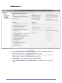
Queues Setup
1.
2.
On the left pane of the Configuration Console, click Queues.
The CNClient tab identifies the primary COMMANDnetwork message queues.
An example of the CNClient tab for Queues.
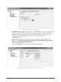
3.
The BLSxxx tab shows queues for a specific BLS and depends on the Manager
Number. For instance, if the Manager Number is 90, the queue name (and tab name) is
BLS90. Under this tab, you can specify up to three different variables:
Installing COMMANDfleet
37
In this example, the Manager Number for the BLS is 90, so the tab is named BLS90.
•
•
•
4.
Threads - This is the number of threads, or message channels, you want to use for the
queue. More threads generally means faster processing, but it also uses more
bandwidth.
Time to live - This is the number of minutes a message will remain in the queue
before it expires.
Polling Interval - This is the interval between checks for new messages.
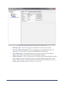
The Trace, PMxx, TIxx, and TGxx tabs show information relating to the MSMQ’s
and are generally not adjusted.
An example of the Trace tab for Queues.
38
Installing COMMANDfleet
In this example, the Signaling Unit Code for the PM is 90, so the tab is named PM90.
In this example, the Signaling Unit Code for the Trimble Integration is 40, so the tab is named TI40.
In this example, the Signaling Unit Code for the Third Party Generic is 30, so the tab is named TG30.
5.
Now, from the Windows Control Panel go to {Administrator Tools > Services}. You
should see two services named CACSISBLSxx and CACSISCNClient.
Installing COMMANDfleet
39
Microsoft Services (Local)
6.
7.
40
Set both services to Automatic in the Startup Type column (change from Manual to
Automatic by right-clicking and selecting Properties).
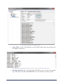
The Microsoft Management Queues reside on the CSIS Server. Go to {Control Panel >
Administrative Tools > Computer Management}. Once the Computer Management window is
open, navigate to {Services and Applications > Message Queuing > Private Queues}. It
should look similar to the following:
Installing COMMANDfleet
Microsoft Computer Management
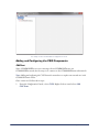
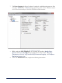
Queue Monitor
The Queue Monitor, located in the left pane of the Configuration Console, is used for
troubleshooting and must be started to run successfully. Queues that are monitored have a
Threshold of messages waiting to be delivered. If the threshold is exceeded, an alert e-mail
is sent to the designated e-mail addresses. On this screen you can:
•
•
•
•
•
•
Start/Stop the Queue Monitor.
Establish the threshold for each queue.
Enter and test the alert e-mail addresses.
The system will copy the messages currently in the queue into a file that will be
attached to the alert e-mail. If you want the file deleted after the e-mail is sent, set
Delete Attachments to True.
Establish a Poll Interval which is how frequently the system will check validate the
threshold levels.
Enter a Resend Interval which is how often an e-mail address will be retried.
Installing COMMANDfleet
41
An example of the Queue Monitor.
Configuring the COMMANDfleet Desktop
1.
42
Click on COMMANDfleet Desktop in the left pane of the Configuration Console. The
General tab displays. Set up this tab according to the recommendations of your IT/
Admin personnel.
Installing COMMANDfleet
An example of the General tab for the COMMANDfleet Desktop configuration.
•
2.
COMMANDseries Version - Enter your COMMANDseries version number in this
field. Note that the CS06 and CS08 2.x versions are considered 6.0.0.0 and that the
CSPlus and CS08 3.x versions are considered 7.0.0.0. Prior to CS06, the 4-place
version, such as COMMANDseries version 5.57.9.19, was used for v5
COMMANDseries.
Set up the Timer Values tab according to the recommendations of your IT/Admin
personnel.
Installing COMMANDfleet
43
An example of the Timer Values tab for COMMANDfleet Desktop configuration.
•
3.
Alerts/Notifications - This is the refresh period for the message grid on the Alerts and
Notification module to get the latest alerts. The time is in milliseconds. The default value
is 10,000 (10 seconds) and is configurable.
Set up the Database tab according to the recommendations of your IT/Admin
personnel. This information is similar to that entered on the {BLSxxx > Database} tab.
An example of the Database tab for COMMANDfleet Desktop configuration.
•
•
•
44
Database Type - Select the appropriate database from this drop-down list.
Server/Username/Password - Enter your database information (if unknown, you can
get these from an ASN file). If running SQL Server, you will also have to specify a
Database.
Use Integrated Security - This is an Integrated Security feature that currently exists
only on the COMMANDfleet Database tab. It allows the application to use the current
Installing COMMANDfleet
•
4.
logged-in COMMANDseries User ID as the COMMANDfleet User ID. For
example, there must be a user in the COMMANDseries USNM table with the same
name as the network or machine logged in user. This does not include the domain
portion of the user. When this checkbox is selected, the Username and Password
fields are made read-only.
Lock Time Out – The time (in minutes) the system will wait for a database response
when a locked table is encountered.
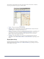
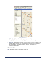
On the Mapping tab, select a map version to use the Mapping module within the
Dispatch Desktop. MapPoint is the only supported option.
An example of the Mapping tab for COMMANDfleet Desktop configuration.
•
•
Version - Select the version you are using from the drop-down list.
Map Template - The map template contains your saved settings--speed limits,
appearance, etc. Specify the location for the template and the program will load it
automatically when it launches MapPoint.
Always Force Map Template On Load - This option will pull up your map
template, which contains your region information. For example, instead of pulling
up all of North America, forcing the map template to load will only load your the
local area you saved as your map template.
Save Your Settings
1.
2.
Select {File > Save Settings}.
A message appears letting you know that the CNClient will be restarted. Select OK.
Installing COMMANDfleet
45
3.
Another message will appear to let you know that the BLS will be restarted as well.
Select OK.
4.
A final message will appear letting you know that you will need to restart the PM, Fleet
Desktop and any third party applications for the changes to take effect. Select OK.
5.
You can now exit the program.
Starting and/or Removing Components
1.
The BLS and the CNClient need to have shortcut icons created on the desktop:
In C:\CSIS\BLS\BLSxxx, right-click CA.CSIS.BLS.Manager.exe. Select the
Send to > Desktop (Create shortcut) option.
In C:\CSIS\CNClient, right-click CA.CSIS.CNClient.Manager.exe. Select
the Send to > Desktop (Create shortcut) option.
2.
To ensure that they will launch upon restarting the computer, you must manually place
a copy of these shortcuts in the Windows Startup folder. Navigate to {Documents and
Settings > All Users > Start Menu > Programs > Startup} or {AppData > Roaming >
Microsoft > Windows > Start Menu > Programs > Startup} and move or copy the two
shortcuts into this folder.
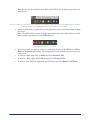
Once these two services are started, tray icons let you easily start or stop these services.
When a service has been started, the icons appear as shown:
3.
46
Installing COMMANDfleet
Note: You can view the descriptions of the BLS and CNClient icons by hovering your mouse over
one of the icons.
In the tray example above, the left icon is the CSIS BLS Service Manager and the icon next to it is the CNClient Service Manager
and looks similar to the COMMANDnetwork tray icon. All the services are started.
4.
Simply double-click (or right-click) on the appropriate tray icon to either Start or Stop
the service.
Note: The CSIS BLS will need to be stopped and started in this manner when updates are made
to the truck file or signaling unit in COMMANDseries.
In this example, both services are stopped.
5.
•
•
•
If, for any reason, you need to remove a component, do not use the Window’s Add or
Remove Programs application. The Configuration Console must be used to remove any
components.
To remove a PM, right-click on PMxx and select Remove PM.
To remove a BLS, right-click on BLSxx and select Remove BLS.
To remove the CNClient, right-click on CNClient and select Remove CNClient.
Installing COMMANDfleet
47
The CSIS Protocol Manager
This section only applies to those using a COMMANDsignal Protocol Manager.
Topics in this section:
How to Start and Configure the CSIS PM
Using the CSIS PM
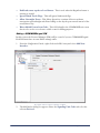
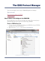
How to Start and Configure the CSIS PM
First you will need to create a shortcut to the PM on the desktop. This is the only way to
launch the PM in Fleet and is required to run when using a CSIS PM.
Create a PM Desktop Icon
1.
2.
To create a shortcut to the PM on the desktop, go to the PM folder of your CSIS folder
(generally stored to your local disk drive).
Right-click on the CSISPM.exe file and select Create Shortcut.
An example of how to create the PM desktop icon.
48
The CSIS Protocol Manager
3.
Move the shortcut to the desktop.
An example of the CSIS PM shortcut.
4.
Right-click the shortcut and select Properties. Navigate to the Shortcut tab.
An example of the CSIS PM Properties window.
5.
In the Start in: field, fill in the name of your PM at the end of the file path. For
example, if your PM appears in the configuration console as PM90, enter PM90 at the
end of the file path.
The CSIS Protocol Manager
49
An example of how the Start In: field should look after the PM has been added.
6.
Select the Apply button followed by the OK button.
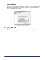
Starting the PM for the First Time
1.
2.
50
Start the PM application by clicking on the shortcut that you just created. Note that if
the Windows Security Alert message appears, click Unblock.
Complete the following information:
The CSIS Protocol Manager
An example of the CSISPM Setup - New Install screen.
•
•
•
Application Type - Select the type of plant to be used: Concrete, Block, or
Aggregate.
Fleet Connection - Select the type of connection you would like to create:
RICs - For two-way radio.
CIC or NIC - For cellular interface or Nextel through a network.
Nextel Telephone - When using a Nextel phone on a serial port.
Host - Select the type of connection you would like to create:
Disabled - This is used with a standalone system.
CSIS MSMQ - This is the default setting for the COMMANDfleet PM.
Note: The following options are no longer supported for Host Connections: CDI RIC
Protocol, Speedcall Model C/D Protocol, and Vehicom Interface.
3.
4.
After selecting the appropriate settings, click OK. A dialog box will appear to confirm
what you have chosen. Click OK to continue.
The main CSIS Protocol Manager screen opens. The next section discusses the
configuration of the PM. Details on using the main screen are discussed in Using the
CSIS PM.
Configuring the PM from the System Menu
Topics in this section:
Configure RICs
Outgoing Message Options
Auto Clear Screens On New Day
New Truck Number Registration
The CSIS Protocol Manager
51
Diagnostic Log
Host Options
Status Key Lockout
Remote VSC2 Settings
Configure RICs
If RIC is selected under Fleet Connection follow these steps:
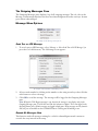
1.
From the main PM screen, select {System > Configure RICs} from the main menu. The
following screen will appear:
An example of how to use the Configure RICs screen.
2.
3.
•
•
•
52
To control two RICs, you must have three or more COM Ports. Unavailable COM
Ports will be grayed out; only the COM Ports you have will be available for selection.
Complete the following information for RIC 1:
Communication Port - Select the COM port to be used for RIC 1.
Mode - If there are three lights located on the RIC, select Single. If there are six lights
located on the RIC, select Dual RIC.
Dual RIC Outgoing Card - If Single is selected under Mode, this feature will not be
accessible.
None - Select when a dual channel RIC is configured to receive on both cards. Text
messaging will be sent out to the designated card that each truck number statusing is
received on.
0 - Select for outbound text messaging on a data channel in a dual channel
configuration.
1 - Select for outbound Text messaging on a voice channel.
The CSIS Protocol Manager
4.
5.
If two RICs are required, follow step 3 to configure RIC 2. If only one RIC is required,
select None under Communication Port for RIC 2. Note that if RIC 1 has a Mode
of Single, you may not access the Mode or Dual RIC Outgoing Card of RIC 2.
If the Send last message of retry interval to all RICs is selected, the message retry
logic starts the retry interval as it currently is, sending the message only on the
registered outgoing RIC card. If the message is still not delivered (no ACK received),
the last message of the retry interval is sent on all outgoing RIC cards. Then, if no ACK
is received, the message has failed. This option is only available if you have a Dual RIC
Outgoing Card selected.
Outgoing Message Options
1.
Select {System > Outgoing Message Options} on the main menu. Configure the outgoing
messages. The following is an example of the recommended settings:
.
These are the recommended settings for Outgoing Message Options.
Auto Clear Screens On New Day
When this option is selected from {System > Auto Clear Screens On New Day}, the screens
will automatically clear at midnight of each new day. A check mark will appear when this
feature is turned on as shown below.
An example of the Auto Clear Screens On New Day option.
Note: A CSL Log file will be generated each day with or without selecting this function.
The CSIS Protocol Manager
53
New Truck Number Registration
1.
To register a new truck number, select {System > New Truck Number Registration} from
the menu. Select an option from the following screen:
An example of how to register a new truck number.
•
Add Truck Number to list and allow message to pass - If this option is selected,
the truck number will automatically be added to the list when the driver presses the In
Service button.
Note: The truck must be in the COMMANDseries truck list.
•
Same as above for XX days then switch to below - If selected, enter the number of
days to add truck numbers automatically. At the end of that time, the truck number will
be blocked from the list.
Block message from Truck Number not in list - If selected, any new trucks which
are not on the list are not allowed to pass. This truck number will only be seen in the
View Communication RIC tabs.
•
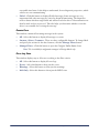
Diagnostic Log
The Diagnostic Log View screen is used to monitor data traffic between the RIC and the
Signaling units in the trucks.
54
1.
Select {System > Diagnostic Log} from the main menu.
2.
To open the current diagnostic file, click on the
button. The NOTES tab displays
errors and events. You can drag the corners of the screen (or maximize it) to see more
information.
The CSIS Protocol Manager
An example of the NOTES tab for the Diagnostic Log View screen.
3.
4.
To open log files, click the
button. A standard browsing screen appears. The log
files are generally located in your PMxx folder and are used for advanced
troubleshooting by Command Alkon Service Personnel. You will need to have the
folders set to Show in order to view the contents.Click on a file name, such as
V20141205.csl, followed by Open. The file name is the date of the file for a 24 hour
period. For example, V20141205.csl stands for the year 2014, the 12th month, and
the 5th day (12/05/2014). The codes of the selected file are displayed in the Diagnostic
Log View.
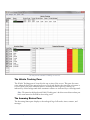
The Diagnostic Truck Watch screen can be used as a filter to display only one particular
truck’s data.To view, click the
button. Select the truck number to be viewed in
diagnostic view by clicking on the Truck dropdown. To update the screen, click the
Refresh button.
The CSIS Protocol Manager
55
An example of the Diagnostic Truck Watch screen.
Host Options
Selecting {System > Host Options} from the menu allows you to enable sending an
unscheduled stop or pour to the host. They are alerts and warnings used when trucks stop at
the traveling status. Select or deselect each check box according to your needs. Refer to the
Remote VSC2 Settings section below for more information and configurations of these
Host Options.
An example of the Host Options screen.
Note: If the current application is not Concrete, the Unscheduled POUR option is not available.
Status Key Lockout
This option will locks a driver’s buttons if all statuses are present. Select it so that a check
mark appears next to the option to turn it on. Re-select it to turn it off.
56
The CSIS Protocol Manager
An example of the Status Key Lockout being turned on.
Remote VSC2 Settings
This screen is used to set the Unscheduled Stop Time, the Automatic In Service
Delay Time, and the Keep Alive Signal for GPRS units.
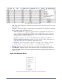
1.
2.
Select {System > Remote VSC2 Settings} from the main menu.
Enter the following information for the Options tab:
An example of the Options tab for Remote VSC2 Settings.
•
•
•
Truck List - Select a truck and enter the information described next.
Automatic In Service Delay Time - After the unit has been off for 4 hours or more,
this is the amount of time, after the VSC3 is powered up, that the unit’s status
automatically goes to IN SERVICE. If set to 10 fro example, ten minutes after VSC3
powers up, the IN SERVICE status is applied automatically. The default setting is 0
minutes, or off. To turn this feature on, enter a value between 1 and 99 minutes.
Send - After entering a delay time, click the Send button so that the VSC3 can enable
Automatic In Service for the specified truck.
The CSIS Protocol Manager
57
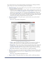
3.
Enter the following information for the Auto Status tab:
An example of the Auto Status tab for Remote VSC2 Settings.
•
•
•
•
When TO JOB is sent (both automatic and manual) - This is used for trucks with
drum features and will clear the load/discharge counters on the VSC.
Pour Detection Count - Enter the number of turns the drum must make in order to
inform the system that the status has changed to POUR.
Unscheduled Stop Time - An Unscheduled Stop (status code 71) is sent when the
current status is TO JOB or TO PLANT and the speed remains below 3 mph for the
amount of time entered in this field. Timing starts when the status changes to TO JOB
or TO PLANT and an Unscheduled Stop is sent each time the programmed time
interval elapses with a speed below 3 mph.
Enforce Mandatory POUR and WASH - An Unscheduled POUR (status code
72) is sent when the current status is TO PLANT and the drum direction changes to
discharge (this requires the truck to have a drum rotation sensor kit and it cannot be
disabled). When an Unscheduled STOP or Unscheduled POUR is received, they
appear as white text on red background in the main window on the Incoming Status
and Truck Tracking panes. If a host is enabled, each unique message is also forwarded to
the host. The default setting is 0 minutes, or off. To turn this feature on, enter a value of
1 to 99 minutes. Note that if the truck is equipped with a drum rotation kit, this field
cannot be disabled.
Note: To use some of these features, such as Unscheduled Pour or Unscheduled Stop, you will need to
have them turned on under Host Options.
4.
58
Enter the following information for the GPRS tab:
The CSIS Protocol Manager
An example of the GPRS tab for Remote VSC2 Settings.
•
Keep Alive signal (GPRS only) - For these units, the VSC3 sends a keep alive signal
(status code 70) whenever the entered amount of time elapses with no network traffic.
This is to keep the connection established for outgoing traffic from dispatch in
COMMANDseries. It is recommended that you start at a 15-minute interval (enter
900 in this field). This section is grayed out when GPRS units are not being used with
the VSC Base.
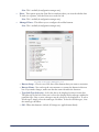
5.
Enter the following information for the GPS tab:
An example of the GPS tab for Remote VSC2 Settings.
•
Store and Forward - For these units, the VSC3 sends a Store and Forward message to
COMMANDfleet that updates the truck’s current location, heading, satellite, and
antenna status on a regular interval. This is most commonly used with the Snail Trail
feature.
The CSIS Protocol Manager
59
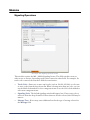
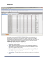
Truck Load Capacity
You must set each truck’s load capacity. To do so, select {System > Truck Load Capacity} from
the main menu. Each truck can be set up for the default set of values or individual values
can be set based on the truck’s load size.
An example of the Truck Capacity window.
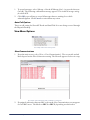
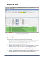
Using the CSIS PM
The following is an example of the main PM screen for the Concrete application. The main
screen consists of three graphical sections and a menu toolbar.
60
The CSIS Protocol Manager
An example of the CSIS Protocol Manager for Concrete.
The Vehicle Tracking Pane
The Vehicle Tracking pane is located in the top section of the screen. This pane becomes
active when the In Service status has been received and displays the time that each status is
received from each truck. Manual statuses, meaning the driver presses a button, are
indicated by a blue background while automatic statuses are indicated by a red background.
Note: The status time displayed on the Vehicle Tracking pane is the driver entered time and may not
be the actual status time available on the tracking screen.
The Incoming Status Pane
The Incoming Status pane displays a chronological log of all trucks, times, statuses, and
messages.
The CSIS Protocol Manager
61
The Outgoing Messages Pane
The Outgoing Messages pane displays a log of all outgoing messages.The red color in the
Message column means that there has been no acknowledgment from the truck yet. It turns
green when acknowledged.
Message Menu Options
An example of the Message menu options.
Send Text or LED Message
1.
To send a text or LED message, select {Message > Select Send Text or LED Message} (or
press the Ctrl+M shortcut). The following screen appears:
An example of the Send Text or LED Message screen.
2.
3.
Select a truck number by clicking on the number or the using arrow keys, then click the
radio button to select a message.
Click OK to send the message. The message will be logged in the Outgoing Messages
pane.
Note: When the GPS Request message is sent, the time the message is sent displays only in the
Outgoing Messages pane. The Veh Ack and Drv Ack columns are blank. This is not logged in the
Incoming Status pane. All other messages are logged in both panes. When messages are sent from the
PM, they are not available on the COMMANDseries Tracking and Scheduling screen.
Resend All Messages Now
This function sends all messages waiting for a vehicle acknowledgment and is meant to
override the retry interval in the setup.
62
The CSIS Protocol Manager
1.
2.
To resend messages, select {Message > Resend All Messages Now} (or press the shortcut
Ctrl+R). The following confirmation message appears: This resends all messages waiting
for vehicle ACK.
Click OK or press Enter to resend all messages that are waiting for a vehicle
acknowledgment. Click Cancel to exit without any action.
Auto Poll Options
This is an old setting for Show All Trucks and Snail Trial. It is now being accessed through
the Dispatch Desktop.
View Menu Options
An example of the View menu options.
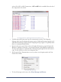
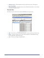
View Communications
1.
From the main screen, select {View > View Communications}. The screen title and tab
labels depend on the Fleet Connection setting. The Host tab appears if a host is set up.
An example of the Host tab for CIC or NIC fleet connections.
2.
If equipped with more than one RIC, a tab on the View Communications screen appears
for each RIC in use. The labels are RIC 1 or RIC 2, depending on which tab is
The CSIS Protocol Manager
63
selected. For CIC or NIC Connections, a CIC or NIC tab is available.Select the tab of
the component to be viewed.
An example of the CIC or NIC tab for the View Communications screen.
•
•
3.
The Messages and Events pane logs all communication activity. The Outgoing
Messages pane logs all outgoing messages in queue. Outbound messages appear in red
while inbound messages appear in blue. Outgoing messages appear very quickly unless
there is a communication problem.
You can select one or more lines and use the right-click menu to copy the data to the
Window’s clipboard. From there, you can paste data into other Windows applications.
To select more than one continuous line, click and drag through the lines you want to
copy. Use the Ctrl key to select non-contiguous lines.
Also from the View Communications screen, you have several options under the View
menu of the toolbar.
An example of the View menu.
•
64
To clear all messages and events, select Clear Messages and Events.
The CSIS Protocol Manager
•
To view raw data, select the Raw Data option. A check mark appears in the menu next
to the option. Repeat this procedure to return to the default readable format.
An example of the CIC or NIC tab when the Raw Data option is selected.
•
•
The Truck Watch option is used as a filter to display data for any one truck.
Depending on your setup, the Load Even Control Panel option may appear. This
configures load statuses from a batch system to forward those statuses to
COMMANDseries (Host) and to the trucks. There is also an option to forward the
load statuses to another COMMANDfleet instance, but this is not commonly used.
An example of the Load Event Control Panel screen.
To make the Load Event Control Panel option available, press Alt + F5. The Paid
Options Enabled screen will appear. You will need to select the Touch-free Load
Event option and move it to the Options Currently Enabled section. It will prompt
you for a password.
The CSIS Protocol Manager
65
An example of the Paid Options Enabled screen (Alt +F5).
A newer method of acquiring the Load Events has been developed for
COMMANDbatch where they are configured in the Configuration Console and the
PM is by-passed. To view these, refer to the appendix section on
COMMANDbatch.
The GPS to HOST Delay option is unused. Previously, it was used with analog
systems.
•
4.
There are also several options under the Commands menu.
An example of the Commands menu.
•
The Send RIC 1 Wakeup option is used to check if the RIC is communicating with
the VSC Base unit. An Error Reporter screen appears after the wakeup has gone out
several times as shown in the following example:
An example of the Error Reporter screen.
•
66
The Set RIC 1 Attack Delay and Set Attack Delay on both RICs options are not
used anymore. Previously, they were used with analog systems.
The CSIS Protocol Manager
•
The RIC 1 Test Tone Control Panel option is only available for analog radios and
not for CDPD or Nextel. It is used to set audio levels or text deviation levels. After
selecting the RIC 1 Test Tone Control Panel option, enter the information on
shown on the following screen:
An example of the RIC 1 Test Tone Control Panel.
•
•
•
RIC Card - Select Card 0 (data card) or Card 1 (voice card).
Select a Test Tone.
1200 Hz - Sends at tone of 1200 Hz (mark, 1).
1800 Hz - Sends a tone of 1800 Hz (space, 0).
OFF - Turns off the tone and un-keys the radio.
The Select Outgoing Messages option displays the messages in the queue that have
not received a vehicle acknowledgment. To delete an outgoing messages, use the Select
Outgoing Messages option and click on the messages you would like delete. Then,
select the Cancel Selected Outgoing Messages option.
Note: Outgoing Messages is the same for all setups but may be labeled differently. Also, the
Cancel Selected Outgoing Messages text will be grayed out unless an outgoing message has
been selected from the Outgoing Messages screen.
The CSIS Protocol Manager
67
Using the COMMANDfleet
Dispatch Desktop
Topics in this section:
Launching the Dispatch Desktop
Toolbar Menu Options
Dispatch Desktop Basics
Modules
Launching the Dispatch Desktop
1.
2.
3.
4.
Select {Start > Programs > Command Alkon > COMMANDfleet} to launch the
COMMANDfleet Desktop.
The Login dialog box appears, prompting you to enter your username and password.
When both the User and Password have been entered, press Enter. When Dispatch
Desktop starts up, it scans the configuration table for the default configuration of the
logged-in user. If the configuration is found at the user, group, or system level, that
configuration is loaded. If no records are found for this user, the system loads an empty
window.
Upon first log in, the window will be blank. you must first set your privileges to gain
access to the desired modules. This is required for each user. Refer to the
Administration and Privilege sections for more information on this process.
Toolbar Menu Options
Dispatch Desktop is very flexible and there are many ways to configure the desktop.
Therefore, some of the screen examples shown in this manual may not look like those on
your desktop.
An example of the Dispatch Desktop menu.
68
Using the COMMANDfleet Dispatch Desktop
The File Menu
The File Menu
•
•
New - This menu option opens a new instance of the Dispatch Desktop.
Save Settings - If this option is selected, the next time that Dispatch Desktop is opened,
it will have the same configuration as the last saved version for the logged-in user (or
the last saved version for the group or system level).
Note: This is only available to the configuration manager.
•
•
•
•
Close Module - This closes only the currently selected module.
Properties - In order to speed up processing time, you can specify a global setting to
select one of the following Truck Retrieval modes: Concrete and Aggregate (default
setting), Concrete, or Aggregate. This causes the Desktop title bar to be updated with
the current Truck Retrieval Mode. If either the Concrete or Aggregate option is
selected, SQL Queries (for Messages/Events and Diagnostics) will pull only the
appropriate truck records.
Exit Dispatch Desktop: - This closes the selected window and includes all modules
contained in the window. If this is the only open window of the Dispatch Desktop, the
entire application will close.
Exit COMMANDfleet - This closes ALL Dispatch Desktop windows and exits the
application.
Using the COMMANDfleet Dispatch Desktop
69
The Modules Menu
Modules Menu
The following modules appear under the Modules menu of the toolbar. Each selection in
this menu opens that named module in the Dispatch Desktop. For more information on these
modules, refer to the Modules section which contains information about these modules in
detail.
Note: You will need to set the privileges using upon the first use of the Dispatch Desktop for users to
have access to certain modules.
Signaling Operations
Messages and Events
Diagnostics
Alerts and Notifications
Water Added Inquiry
Mapping
Administration
Privilege
Truck Configuration
70
Using the COMMANDfleet Dispatch Desktop
The View Menu
The View Menu
If an option is checked, then that option is currently active.
•
Status Bar - This option toggles the status bar (ON and OFF) at the bottom of the
Dispatch Desktop window. If the check-mark is present, the status bar appears with the
date and time and any other applicable information.
An example of the Status Bar and Design Mode.
•
Module Captions - If this check-mark is present, captions are displayed. Also, the
Menu, Auto Hide, and Close options are removed from the upper right of the
module window as shown below.
Note: If more than one module is open within a window, a tab appears for each module. This
allows you to go back and forth between modules by selecting a tab.
Using the COMMANDfleet Dispatch Desktop
71
An example of Module Captions.
•
Design Mode - A check-mark must appear next to Design Mode in the menu in
order to customize columns, adjust the screen layout, and to manage filters. When ON,
the status bar displays the text DESIGN MODE against an orange background as shown
in the example above. To save your configuration for a later session, select {File > Save
Settings}.
Note: This is only available to the configuration manager.
The Format Menu
The Format Menu
•
72
Font - This option opens a standard Font dialog box where you can select the font type,
style, and size. The default font type is Microsoft Sans Serif, with a style of Regular,
and a size of 8.
Using the COMMANDfleet Dispatch Desktop
An example of a standard Font dialog box.
The Window Menu
The Window Menu
This menu displays all the Dispatch Desktop windows that are currently open (not necessarily
modules). To bring a window to the forefront (if there is more than one window open),
select it from the list.
The Help Menu
The Help Menu
This menu contains the standard About screen which gives you your COMMANDfleet
version information.
Using the COMMANDfleet Dispatch Desktop
73
An example of the About screen for COMMANDfleet.
If you select the File Info button, a window that displays all the file versions within
COMMANDfleet will open.
An example of the File Info window that displays when the File Info button is clicked.
74
Using the COMMANDfleet Dispatch Desktop
Dispatch Desktop Basics
Manipulating Module Columns
An example of module columns.
Moving
If you need columns to display in a specific order, you may move a data column to another
location by clicking the column header and dragging it. In the following example, a column
is in the process of being moved to the right of another column. Red arrows let you know
where the column will be located once you take your finger off the mouse.
Note: This can only be done in Design Mode (which is only available to configuration
managers).
An example of column moving.
Sorting
You may choose to sort columns in ascending or descending order. If you click on any
column heading within the grid, all rows are sorted on that column in ascending order (an
upward-facing triangle appears in the column heading). Click again and all rows will be
Using the COMMANDfleet Dispatch Desktop
75
sorted in descending order (an downward-facing triangle appears in the column heading).
For example, a triangle pointing up indicates the column is sorted in ascending order.
An example of column sorting.
Grouping
If you need to look at data for a particular group, you may do this by dragging any column
header to the area labeled Drag a column header here to group by that column.The
table is then grouped by that column. Click on the plus sign to expand the group’s detail or
the minus sign to hide the group’s detail. To remove this sort option, drag the column name
back to the table grid.
An example of column grouping.
Filtering
You may choose to have all data displayed (default), specific data displayed, or a customized
filter. For filtering options, click the funnel icon to the right of any column heading.
76
Using the COMMANDfleet Dispatch Desktop
An example of how to enter filter criteria.
•
•
•
•
•
All - This option displays all items associated with the field you clicked on. This is the
default filter.
Custom - This option opens a custom filter criteria window. The funnel icon will turn
blue to indicate that a filter has been set.
And/Or conditions - These two option buttons are applicable only when two or
more conditions are set. With the AND condition, all conditions must be met to
return a result set. With the OR condition, each condition can return a result set
independent of the other conditions.
Operator - Select an operator, such as Equals or Less Than. The Like and
Matches Regular Expression options are more advanced. More information on
using these filters may be found in the Appendix section.
Operand - This is the entity the operator is working on. For example, with the
condition Truck >= 1007, the operator is >= and the operand is 1007.
Blanks - Displays only the rows that have no entries for the field you clicked on.
Non-Blanks - Displays only the rows that have entries for the field you clicked on.
(Specific Item)- Select a specific item (text or numeric) to display all occurrences of
that item only.
Right-Click Context Menus
An example of the context menu when you right click in a module with columns.
Using the COMMANDfleet Dispatch Desktop
77
If you right-click on any of the column headings on the Diagnostics or Messages and Events
panes, you get one or more of the following context menu options:
•
•
Enable Grouping - This option allows you to group a data set (such as trucks, plants,
or time) by a particular data column.
Multiple groups are supported. For example, while reviewing numerous statuses for
a day, you can select Enable Grouping for the Truck Code data column and view
all statuses for each truck. Also, you can group the From Plant data column and
then group by Truck Code to view each truck status by plant. To show more detail
for a group, click the plus sign on the left. To disable the grouping, right-click again
and deselect this option (or drag the button back to the grid).
Customize Columns - This option opens a window where you can select which
columns to display.
Note: This is only available in Design Mode.
An example of the Customize Grid Columns screen.
Visible - Make individual selections by selecting or deselecting the checkbox on
each row. The selected rows are visible and the deselected rows are hidden.
Header Text - This is the text that is shown in the grid header for that column and
is editable. If you make changes, make sure that the name identifies the column.
Select All / De-Select All - These buttons allow for quick selections of all rows.
OK - When this button is clicked, all changes are applied immediately.
Favorites - Save custom views with Customize Columns, Grouping, Filtering, and/or
Sorting. Click Add and name the Favorite. Organize allows a user to rename/delete
existing Favorites.
Note: This is only available for the Diagnostics pane.
•
•
78
Export to Excel - This option allows you to export a table to an Excel spreadsheet.
Using the COMMANDfleet Dispatch Desktop
Note: This is available for configuration managers only.
•
Print - This option opens the Print Preview window where you view the tabular data.
To send it to a printer, click the Print icon on the far left.
Note: This is available for configuration managers only.
•
Manage Filters - This allows you to configure the toolbar buttons.
Note: This is available for configuration managers only.
An example of the Configure Toolbar Buttons screen.
Button Setup - Choose one of the three filter buttons that you want to customize.
Button Name - You can keep the current name or rename the button in this text
box. If you make changes, make sure that the name identifies the function.
Type/Sub-Type Selection - Select the data to be displayed in this selection box.
The plus sign to the left of this row is selected to display all the sub-types within the
particular type. One or more sub-types may be selected to be displayed as. To select
all sub-types, simply select the main type checkbox. To deselect all sub-types, clear
the main type checkbox.
OK - When this button is clicked, all changes are applied immediately.
Using the COMMANDfleet Dispatch Desktop
79
Modules
Signaling Operations
An example of the Signaling Operations module.
This module requires the MS - Mobile Signaling license. The fields on this screen are
either active or inactive, depending on the values entered in other fields. For example, if a
truck code is entered, the next three fields become inactive.
•
•
•
80
Truck Code - Enter one or more truck codes (such as 100,101,102,106) or select one
or more codes from the drop-down list. When selecting more than one code, you can
use the Shift-click method to select contiguous items or use the Ctrl+click method to
select non-contiguous items.
Signaling Unit- The default signaling unit should appear here. If necessary, select a
unit code from the drop-down list. If more than one truck is selected, this field may be
inactive.
Message Text - If necessary, enter additional text for the type of message selected in
the Message field.
Using the COMMANDfleet Dispatch Desktop
Messages and Events
An example of the Messages and Events module.
The Messages and Events module will hold information for about an hour before it is
automatically dropped off the screen.
Messages Pane
This form keeps you up-to-date on all current messages in the system.
•
•
•
Note: There is a common color code for messages. Messages with a red background have been sent
but not received; a yellow background indicates the vehicle has received the message; a green
background means the driver has acknowledged receiving the message.
All - Select this button to display all messages or events.
Statuses / Alerts / Common - There are three configurable buttons. To change labels
and specify the actions for the three buttons, click the Manage Filters button.
Manage Filters - Click this button to open the Configure Toolbar Buttons form.
Note: This is available for configuration managers in Design Mode only.
•
Pending - Click this button to display all pending messages. A dispatcher may want to
know which messages have not been delivered and may not get delivered in a
Using the COMMANDfleet Dispatch Desktop
81
•
reasonable time frame. It also helps to understand, from a diagnostic perspective, which
vehicles are not communicating.
Failed - Click this button to display all failed messages. Some messages are very
important while other messages are critical to dispatch functioning. The dispatcher
needs to know which messages failed and will not reach the driver. A determination can
then be made on how to proceed. This also helps you determine whether or not the
driver is accountable for receiving the message.
Events Pane
This window contains all incoming messages in the system.
•
•
•
All - Select this button to display all messages or events.
Statuses / Alerts / Common - There are three configurable buttons. To change labels
and specify the actions for the three buttons, click the Manage Filters button.
Manage Filters - Click this button to open the Configure Toolbar Buttons form.
Note: This is available for configuration managers in Design Mode only.
Error Log Pane
This window displays any or all errors according to the filter criteria.
•
•
•
•
82
All - Select this button to display all error logs.
Errors - Select this button to show just the errors.
Warnings - Select this button to show just the warnings.
Info Only - Select this button to show just the INFO rows.
Using the COMMANDfleet Dispatch Desktop
Diagnostics
An example of the Diagnostics module.
This module retrieves historical data for troubleshooting and proactive detecting of
signaling issues. It allows you to review Messages, Events, Errors, GPS, JBUS, JBUS
Threshold, and Water Added information. The Transactions pane is the main area for your
pertinent data. The data in the grid is determined by the search criteria and the view
(Transactions, Errors, Trace Log, or Queues tab).
•
•
•
•
From Date / To Date - These two fields allow you to restrict the data shown to a
certain range of dates and times.
Trucks - From this dropdown list, select one or more trucks to narrow the list of
retrieved data. To select more than one truck, Ctrl+click non-contiguous items or
Shift-Click a contiguous range of items.
Plants - From this drop-down list, select one or more plants to narrow the list of
retrieved data. To select more than one plant, Ctrl+click non-contiguous items or
Shift+click a contiguous range of items.
Retrieve Data - Click this button to retrieve the data according to the selected search
criteria.
Using the COMMANDfleet Dispatch Desktop
83
•
•
Maximize Grid - Click this button to hide the left Favorites pane. Click again to
restore the left pane.
Advanced Options - Click this button to enter a limit for the number of rows shown
on the table for quicker access.
Favorites Pane
The Favorites pane on the left starts with just Default as the only favorite.
An example of the Favorites pane.
•
•
•
84
Add - To add a favorite, click this button and enter a name to add to your Favorites list.
Delete - To delete a favorite, select it and click this button. A confirmation message
asks if really want to delete this favorite.
Save - To save your changes, click this button.
Using the COMMANDfleet Dispatch Desktop
Alerts and Notifications
An example of the Alerts tab for the Alerts and Notifications module.
This module provides the Dispatcher and Fleet Manager the capability to monitor real time
priority messages, statuses, and event notifications received from trucks when used as part
of the dispatcher tools in COMMANDseries.
Alerts Tab
• Refresh - This button forces a refresh of the messages grid ahead of the configured
polling period.
The grid displays the current (24 hours) view of alerts into the system. A few of the grid
columns are defined as follows:
•
•
•
Acknowledged Users - The first user to acknowledge the message. If more than one
user acknowledges the message, only the first user is logged.
Acknowledged Time - The time that the message was acknowledged.
Elapsed Time - The amount of time in minutes from the time the message was
received from the system (BLS) and the time it took for a user to acknowledge the
message.
Using the COMMANDfleet Dispatch Desktop
85
Configuration Tab
This tab allows you to list all incoming messages (canned and free-text) and to select
specific messages as alerts.
•
•
•
•
•
•
•
•
•
Signaling Unit - Select a signaling unit from this dropdown list.
User Name / Group Name - Select one or more items from the dropdown list (select
the checkbox next to each user name). After selections have been made, click outside
the dropdown list box to return to the form.
Plus (Select All) - Add all items from the drop-down list (this is not recommended
for a standard configuration).
Minus (Clear All) - Remove all items from the list.
Priority - Select from the following options:
High - Displays a prompt that remains on screen until acknowledged. The user
cannot continue other work until receipt of the message is acknowledged.
Medium - Displays a prompt that remains on screen until receipt is acknowledged.
The user can continue with other work.
Low - Temporarily displays a message box for a user-configurable time period and
then disappears. The user can continue with other work.
Plant / Truck - If the All checkbox is selected, all plants/trucks are included in this
configuration. If this checkbox is cleared, the dropdown list becomes active. Select one
or more of the checkboxes next to each plant/truck.
Add - Click this button to submit the configuration criteria to the server for
processing.
Update - Click this button to update the current criteria to a new configuration. Once
selected, the only available button is the "Add" button.
Delete - Click this button to permanently remove the criteria from the alert process.
Cancel - Click this button to cancel and roll back any changes made prior to clicking a
delete or update button.
(Grid Row) - Clicking on a row in the grid causes the specific configuration to be
loaded, filling the items in the configuration area. The Add button is hidden and the
Cancel, Delete, and Update buttons become available.
Under the Status tab, select one or more of the status items to be included in the alert.
The JBUS tab lists all incoming JBUS events and allows the User to select and subscribe to
specific JBUS Events This tab is used to set up the JBUS configuration:
86
Description - Select a description that corresponds to the JBus event that you wish
to be notified.
Units - From this dropdown list, select a unit type that is based on the description
selected.
Threshold - The minimum or maximum value is set in this numeric field. If you
enter a value that is above the maximum (the Above option must be selected) or
below the minimum (the Below option must be selected), the field will default to
the appropriate minimum or maximum value.
Using the COMMANDfleet Dispatch Desktop
Note: This is only enabled when the Units field is selected.
Duration - This numeric field sets the duration for the Threshold value.
Note: This is only enabled when the Units field is selected.
Under the Message tab, you can select (subscribe to) one or more specific Message Types
to be included in the alert.
Alert Messages
If multiple screen prompts are displayed concurrently, they are to be prioritized by prompt
time (earliest to latest) within Priority (High to Low). The screen prompts requiring receipt
acknowledgment (Priority High and Medium) display the following information: Truck
Code, Time Received, Message/Event/Status notification, and an OK button to
acknowledge receipt. The screen prompt not requiring receipt acknowledgment (Priority
Low) displays the following information: Truck Code, Time Received, and Message/Event/
Status notification.
Water Added Inquiry
An example of the Water Added Inquiry module.
In addition to the Water Added (WA) license, water meters are required for this module.
Using this module, you can retrieve Water Added Events by Order Date/Code, Ticket
Using the COMMANDfleet Dispatch Desktop
87
Code, Customer Code, Project Code, Truck Code, and/or Plant Code. You can review the
Water Added Event information by the:
•
•
•
Batch
Adjustment Water – This is water added after Loading and before Pouring.
Placement Water – This is water added during the Pouring and Wash status.
Mapping
An example of the Mapping module.
This module requires the MO - Map Order Entry and/or the MT - Map Truck Tracking
licenses (if Snail Trail is used, the ST license is also required).
Note: The mapping pane contains a map which is displayed by your third-party mapping software.
On this pane, the map and the toolbar above it have differences based on the map selected in the
configuration console. The maps themselves look similar, but the context menus and toolbars are very
different. Also, the icons are not the same, such as different symbols for GPS on truck snail trail and
slightly different colors for trucks and some indicators.
Monitoring Group
On the top left of the Mapping window, you can select from one of the following items for
monitoring: Trucks, Dispatch, Deliveries, or Lookups. The controls (such as options
88
Using the COMMANDfleet Dispatch Desktop
and checkboxes) that display below this group depend on the selection here. Only the
selected option will have its group of controls visible.
Monitoring Group
•
•
•
•
Trucks - This is the default monitoring group.
Dispatch - This is automatically selected when Truck Locate is initiated from the
COMMANDseries Tracking & Scheduling screen.
History - This option is chosen for an historical snail trail of where a truck has been. If
you click the down arrow to the right of Truck Search Criteria, a search screen
appears where you can set criteria such as a date range and codes for customers,
projects, orders, tickets, plants, and trucks.
Lookups - This option allows you to get the best routing information from the
mapping tool. Select Show Shortest Route or Show Best Route depending on your
needs.
Display Options Group
Click the plus sign on the left to see all the display options. To roll it back up, click the
minus sign. You can select Job Site and/or Plants for Delivery, depending on what you
want to appear on the map.
Using the COMMANDfleet Dispatch Desktop
89
Display Options Group
•
•
Follow Me - If this checkbox is selected, the selected truck (or trucks) are shown on
the map. This function automatically displays chosen events on the map as they are
received in the database.
Snail Trail - If this button is selected, the path of the selected trucks are shown on the
map. You can also select any of the following checkboxes to add more event details to
the snail trail: JBUS, Water Added, Statuses, Messages, Unscheduled Stop,
Unscheduled Pour, Other.
Administration
Note: This module is available for configuration managers only.
90
Using the COMMANDfleet Dispatch Desktop
Administration Module
This module is used for troubleshooting XML messages for 3rd party vendors and
interfaces. It contains information for XML tags such as definitions, expected strings, setup
and the basic structure of messages. Command Alkon Service Personnel use this module to
do advanced research on XML structure.
Privilege
Note: This module is only available to configuration managers.
Using the COMMANDfleet Dispatch Desktop
91
Privilege Module
This module is used to set user privileges. These users are the same as COMMANDseries
users. Initially, user access is limited to Plant Privilege so you will need to configure the
desktop to expand privileges to your users.
1.
2.
Note: This module CANNOT be used to edit existing users and cannot be changed once set.
From the drop-down list, choose a User Name or Group. This must be a valid user
name from the COMMANDseries database. If a group is selected, the Group check
box will be marked.
Choose a Form on the left and the Type of privilege (Add, None) on the right. The
following is a breakdown of all options currently allowed in the Privilege module. They
are grouped by task category as to who might have them and their purpose; what is
required depends on the duties of the person.
Privileges for Normal Operations
• Mapping – The map module contains the following sub-options (license permitting):
Mapping – Snail Trail – Allows the snail trail for trucks.
Mapping – Truck – Allows for the truck map location.
Mapping – Delivery – Allows for the delivery-location GPS coordinate mapping.
Signaling Operations – Allows messages to be sent to trucks.
Messages and Events – Allows the Messages/Events/Errors module.
Water Added Inquiry - Allows if water added functionality is necessary.
•
•
•
92
Using the COMMANDfleet Dispatch Desktop
Optional Privileges
• Diagnostics – Allows you to find previous truck and signaling issues.
• Allow user to save map zoom selection – Allows you to save a new default
•
geographical location on the map for use when fleet is loaded or a zoom to all for no
map pins takes place.
Design Mode – Allows for customization of columns, sort order, and filter criteria for
grids that support this.
Administrator Privileges
• Privilege – Allows access to the Privilege module to assign privileges to users.
• Truck Configuration – Allows access to JBus configuration and some VSC
•
•
configuration information for the trucks.
Administration – Allow changes to the text mapping for various truck signals.
Advanced Diagnostics – Deprecated function; being removed.
Truck Configuration
Truck Configuration Module
Using the COMMANDfleet Dispatch Desktop
93
This module allows you to set the various JBUS parameters on your trucks. The top two
panes are for the JBUS templates, which you can create and edit. The bottom pane contains
a grid displaying every truck (each containing up to 32 parameters).The JBUS Template List
pane contains a list of JBUS templates that may be applied to trucks. Click on any of the
template names to populate the details pane on the right.
The Selected Template :: Standard Template pane represents the set of values associated
with the selected template.
The primary purpose of the JBUS Thresholds pane is to apply templates to vehicles as well
as define the vehicle-specific slots. The grid contains an entry for every truck, with 32
parameters available for each truck.The slots that are reserved by the template are shown in
light green and the remaining slots that must be defined at the vehicle-level are shown in
white. The vehicle slots are defined in the same fashion as the slots in the template. The
JBUS THRESHOLD table populates this grid. The rows that are not used are labeled
Inactive.
Truck Configuration Fields
This section discusses all the fields on the Truck Configuration module. They may not be in
the order displayed on any one pane or the JBUS PID table.
•
•
•
•
•
94
Entry - This 2-digit entry index represents the slot number within the template. The
default value can be between 1 and 32. Only the default number of slots should be
displayed in the grid. The remaining slots are reserved for use on a specific vehicle. The
default number of slots are white, indicating they are editable. The remaining vehicle
specific slots are light green, indicating that they are not editable.
MID (Message Identification) / PID (Parameter Identification) - The combination of
MID and PID identifies a specific value and what device put the value onto the JBUS.
The 3-digit MID is not a user-editable field. It is derived from the PID table when a
user selects a value from the PID Description column in the grid. The MID is
described in SAE J1587.
PID Description - Once the template is selected, the MID, PID, and PID
Description values are populated from the JBUS PID table into this grid as default
values. The PID and MID are non-editable fields, but the Label field is editable, if
necessary.
Threshold Value - This 8-digit field represents the numerical value of the threshold
to be monitored. For example, to monitor road speeds above 70 mph, the threshold
value is set to 70. This value must be within the minimum and maximum range
specified in the JBUS PID table (which is based on the value in the Is English Units
field - either English or Metric). An error message is displayed if the threshold value is
not within the range.
Direction - This is a dropdown list of values used in conjunction with the Threshold
Value field. The direction can be one of the following:
O - Represents over the threshold.
E - Represents equal to the threshold.
U - Represents under the threshold.
Using the COMMANDfleet Dispatch Desktop
N - Represents never equal to the threshold. This is used to temporarily turn off the
threshold without deleting it from the unit.
P - Represents power-up. If this is set, the unit sends the current JBUS data for that
MID/PID combo 30 minutes after power-up of the unit.
Trigger - This 3-digit number represents the delay time in seconds after the threshold
is triggered for the JBUS data to be sent from the unit to the BLS.
Retrigger - If the value remains over the threshold after it is triggered, this 3-digit
number represents the time in minutes in which the JBUS data is resent from the unit.
Precision - This drop-down list allows you to select the precision of the numeric value
(from 0-9). It is based upon the MID/PID combination that is selected.
Label - This 6-character label is displayed on the VSC unit. The default value is taken
from the JBUS PID table when selected from the Description drop-down list. This
field is editable, if necessary, but make sure the meaning is clear.
Is English Units - This is a Yes/No radio button indicating whether or not the value is
English (Yes = English, No = Metric). This is utilized when the values are returned
from the unit to obtain the correct units from the JBUS PID table.
Status - This column contains the following values:
IN PROCESS - This yellow-colored cell indicates that the entry has been edited
and is waiting for the transaction to be processed.
PROCESSED - This indicates that BLS has sent the threshold out to the vehicle
and has received an ACK back from the vehicle. This column is the same color as
the non-editable columns (green).
ERROR - This red-colored cell indicates that BLS has tried to send threshold
values to the vehicle, but the vehicle has not acknowledged receipt.
Status Update - This date is updated whenever the record is updated, either by the
BLS or Fleet Manager.
Truck Code - This 10-character field is the designation for the truck and is taken from
the TRUC table.
Radio Code - This 16-character field is the designation for the radio and is taken from
the TRUC table.
Sign - This value is either "S" (signed) or "U" (unsigned).
Units - This is the units-of-measure for the threshold value. It is measured in either
English or in Metric units.
Scaling Factor - This is a number used by the VSC unit to scale the event threshold
values in either English or Metric units.
Min/Max Range - These four values from the "JBUS PID Table" are used to
determine the Min/Max range of threshold values in both English and Metric units.
•
•
•
•
•
•
•
•
•
•
•
•
•
Truck Configuration Context Menu
The majority of the functionality of this module comes from the right-click context menu
when clicked over a grid. The context menu's for the top two grids (templates on the left
and template details on the right) have the following options:
Using the COMMANDfleet Dispatch Desktop
95
•
•
•
•
•
Add Template - The dialog Template Name appears. Up to 30 characters can be entered
for the template name. Click OK and a new row is added in the template list.
Remove Template - This removes the currently selected (highlighted) template. A
confirmation message appears. Click OK and the template is removed from the
template list. Any truck that was using a removed template is set to the Standard
Template (which cannot be removed) and all of its values are initialized.
Change Template Name - The dialog New Template Name appears. Up to 30
characters can be entered for the new template name. The template name is updated for
all trucks using the previous template name.
Add Trucks - Before selecting this option, select a template that this truck will be
associated with. When this option is selected, a dialog containing a grid appears
displaying all the trucks. Select one or multiple trucks and click OK. The trucks are
added to the bottom threshold grid with the associated template that was selected.
Update Assigned Trucks - This updates all assigned trucks that are currently
associated with the currently assigned template. If the Standard Template was selected,
only the truck rows using the Standard Template are updated. The changes are not
automatically updated to the truck when a change is made to a template. This option
must be used whenever an update occurs on the template.
The context menu for the bottom (threshold) grid has the following options:
•
•
•
•
Remove Trucks - This removes the truck from the "JBUS Thresholds" grid. A
warning message appears stating that all pending messages should be delivered to the
truck before deleting it.
Apply Selected Template - This changes a truck’s template to the currently selected
template. If one or more rows are selected that contain the same truck, then all rows
containing the truck are updated with the template information.
Refresh Selected Template - This updates the truck’s template with the most recent
changes.
Synchronize Trucks - This iterates through all rows within the threshold grid
creating a list of trucks that have a status of IN PROCESS. A Message 29 is created
containing the truck list. This is sent through Tracking and Scheduling to the BLS
where it is then sent to the VSC unit with the list of JBUS updates. The BLS then
updates the status to PROCESSED when the VSC unit acknowledges the update.
JBUS PID Table
To open this table, click on the JBUS PID Table button at the top of the form. This table
contains all information for the available PID/MID combinations. All the values to populate
this table can be found in SAE J1587.
The script that creates the JBUS PID table also populates it with ten default PID/MID
combinations. The SQL script that should be run in conjunction with the implementation
of the Truck Configuration module adds the additional range fields and populates them
with the specified ranges as shown above.
The new fields that update the table consist of minimum and maximum ranges based on
English or Metric units-of-measure. All fields must be filled in when entering a new PID.
96
Using the COMMANDfleet Dispatch Desktop
The minimum and maximum restrictions are applied after selecting a PID Description in
the threshold grid (bottom) or detail grid (top right). If the Is English Units checkbox is
set to Yes, then the Min/Max English restrictions are applied to the threshold value. If the
checkbox is set to No, then the Min/Max Metric restrictions are applied to the threshold
value.
Common Procedures for the Truck Configuration Module
To add a template to an unlisted vehicle:
1.
2.
3.
4.
Highlight the desired template in the upper grid that you want to apply to a vehicle.
In the bottom grid, right-click and select "Add Trucks". A selection box appears with the
list of all trucks displaying Signal Unit Code, Truck Code, Description, Owner Name,
and Radio Code.
You can select one or many trucks using Shift+Click and Ctrl+Click.
Click OK. A confirmation dialog appears asking if you want to assign the template to
the selected trucks. The truck is added to bottom pane with the template applied and
the status column is set to "IN PROCESS" for all slots and the "Status Update" is set to
the current date and time.
To remove a truck from the list:
1.
2.
Highlight the truck in the lower grid.
Right-click the mouse and select "Remove Trucks".
A warning message appears to ensure that there are no pending messages for the truck
since the rows are going to be deleted from the table and the truck will not be "in sync"
with this grid.
3.
Click OK to delete this truck or Cancel to return without deletion.
To apply a template to a truck in the list:
1.
2.
3.
4.
Highlight the template to be applied in the upper grid.
Highlight the truck in the lower grid that you want the grid applied.
Right-click and select "Apply Selected Template". A confirmation message appears
asking if you want to apply the selected template to the selected truck or trucks.
Click OK to apply the template. The template slots are applied to the truck only. If
there are truck-specific thresholds in place they should not be overlaid. Also, the status
on all template slots is changed to "IN PROCESS". This should have no effect on the
vehicle-specific slots. They should remain as is.
To refresh a template to a truck or set of trucks:
1.
2.
3.
Highlight the selected truck in the lower grid.
Right-click and select "Refresh Assigned Templates". A confirmation message appears
asking if you want to refresh the selected truck or trucks to the assigned template. If OK
is selected, this reapplies the templates already assigned to the selected truck or trucks.
The Status on all template slots is changed to "IN PROCESS". This should have no
effect on the vehicle-specific slots. They should remain as is.
Using the COMMANDfleet Dispatch Desktop
97
To synchronize the information with the vehicles in the field:
1.
2.
98
Tracking and Scheduling must be running in order to accept the "Message 29" text and
convert it to a message to be passed through COMMANDnetwork.
Right-click and select "Synchronize Trucks". This passes the text to create a
COMMANDnetwork "Message 29" truck list to Tracking and Scheduling. The BLS
then handles the new message and processes the JBUS thresholds.
Using the COMMANDfleet Dispatch Desktop
Appendix
Product Integration
The BLS Signaling Tab
Optimization
BLS: Signaling Tab
•
•
•
Appendix
Create CERLY Condition on Driver Login - This creates a CERLY condition
when a driver logs in earlier than the set call-in time for that driver.
Enable Travel Time Polling
Ready To Load Message Code - This is a pre-load feature that allows a ticket to print
but does not send the mix to the batch panel until the driver presses a button and a
condition or event is met.
99
•
•
•
Use Driver Login Offset Minutes - This backlogs time 5 minutes from the original
punch-in time to allow time for vehicle inspection before the Optimizer uses the
driver.
Warn for Max Age of Concrete - Select this checkbox to make the field available for
entry in COMMANDseries.
Remove Auto End Conditions
EDX
BLS: Signaling Tab
•
100
Enable EDX Services - This option turns EDX integration on or off. If enabled, the
following two fields are available.
Service Port Number - This refers to the EDX port number.
Subscribe to Endload - This subscribes to the Endload plugin.
Appendix
COMMANDbatch
BLS: Signaling Tab
•
•
•
•
Appendix
Receive BeginLoad from COMMANDbatch - This is commonly referred to as
VSCSTART and is valid for COMMANDbatch users only.
Receive EndLoad from COMMANDbatch - This is commonly referred to as
VSCEND and is valid for COMMANDbatch users only.
Port Number - Leave the listening port at 2202 (default).
CS to COMMANDbatch is ULINK interface - If ULINK is used, select this
checkbox.
101