1
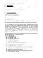
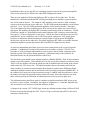
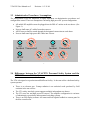
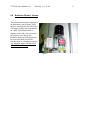
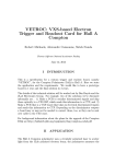
Vertical Test Area
Personnel Safety System
Users Guide
Revision 2
May 10, 2004
Prepared by the JLab Safety Systems Group
i
Table of Contents
1
THINGS TO KNOW ............................................................................................................ 2
2
REFERENCE DOCUMENTS............................................................................................. 2
3
INTRODUCTION................................................................................................................. 2
3.1
HAZARDS ......................................................................................................................... 4
3.2
MITIGATION ..................................................................................................................... 4
3.3
ADMINISTRATIVE PROCEDURES / ASSUMPTIONS ............................................................. 5
3.4
DIFFERENCES BETWEEN THE VTA/CPTS PERSONNEL SAFETY SYSTEM AND THE CEBAF
PERSONNEL SAFETY SYSTEMS. .................................................................................................... 5
4
STAFFING ............................................................................................................................ 6
5
PSS LOGBOOK.................................................................................................................... 6
6
PSS EQUIPMENT ................................................................................................................ 7
6.1
6.2
6.3
6.4
6.5
6.6
6.7
6.8
7
PSS STATUS PANEL ......................................................................................................... 7
RF MUX CHASSIS ........................................................................................................... 7
DEWAR LAYOUT .............................................................................................................. 8
AC SWITCH BOX ............................................................................................................. 9
MAGENTA BEACON........................................................................................................ 10
AUX. CRASH PANEL ...................................................................................................... 10
RF SWITCH BOX ............................................................................................................ 10
RADIATION MONITOR ALARMS ..................................................................................... 11
VTA OPERATION............................................................................................................. 12
7.1
VTA OPERATOR REQUIREMENTS .................................................................................. 12
7.2
PSS OPERATION ............................................................................................................ 12
7.2.1
Enabling High Power RF Amplifier AC Power ................................................... 12
7.2.2
PSS Trips .............................................................................................................. 13
7.2.3
RF Enable.............................................................................................................. 13
7.2.4
Emergency Crash Switch (ESTOP) ...................................................................... 13
7.3
RF CABLE CONFIGURATIONS......................................................................................... 14
7.3.1
Dewar High Power RF Configuration .................................................................. 14
REVISION HISTORY ............................................................................................................... 16
VTA PSS User Manual-rev2
1
Revision - 0 5/11/04
2
Things to Know
All PSS devices are under personnel safety configuration control. Only Safety System Group
personnel may access, modify, or alter these devices.
Activating ANY crash switch will shut off ALL RF sources.
2
Reference Documents
JLAB VTA PLC Logic Specification
JLAB VTA Standard Operating Procedure
3
Introduction
The VTA is the cold test facility for prototype and production versions of both 805MHz and
1497MHZ RF cavities. Low and high power amplifiers are used for testing, however only the
high power amps have the potential to produce hazardous ionizing and non-ionizing radiation.
The VTA Personnel Safety System is an engineered interlock system to help protect personnel
from exposure to prompt ionizing radiation (PIR) and radio frequency non-ionizing (microwave)
radiation that results from operation of the VTA test dewars in the JLab SRF test lab building
(building 58). The Personnel Safety System must be able to ensure that high power RF is only
allowed to operate when the RF systems are configured to safely do so. Also, ionizing and nonionizing (RF) radiation monitors are located near areas that would be most likely affected by
improper or unanticipated operation of the dewars. If a fault is detected on one of these systems,
all RF sources are shut off.
Other PSS conditions for successful operation of high power RF include no area radiation alarms
and proper configuration of the RF switching systems.
The VTA PSS consists of:
• Dewar shield interlocks
• Dewar radiation monitors
• Dewar radiation warning beacons
• Area radiation monitors
• Area radiation warning beacons
• Area radiation audible alarm
• PSS PLC logic control system located in the PSS rack
• PLC logic program that runs on each of two PLCs.
• Production Amplifier rack AC contactors
• Dewar PSS AC power contactors located on the front of dewars 3 through 8.
• Dewar RF Switch box located on the front of each of dewars 3 through 8.
• PSS Status Panel chassis located in the PSS rack.
• PSS RF Mux Chassis located in the PSS rack.
• PSS Emergency Crash (ESTOP) switch located in the R&S control room.
• All PSS conduit, cable, and wiring.
VTA PSS User Manual-rev2
Revision - 0 5/11/04
3
In addition to these devices the RF mux switching systems located in the production amplifier
racks are not owned by the PSS but are under PSS configuration control.
There are two methods of delivering high power RF to a dewar device under test. The first
method uses a dedicated production RF switching and high power amplifier system located in
rack #24 in front of dewar 6. The output of a RF amplifier can be routed via a RF switching
system to the desired dewar device under test. The 805 MHz production amplifier can be routed
to dewars 7 or 8. The 1497 MHz production amplifier can be routed to dewars 3 through 8.
The second method of delivering high power RF to a dewar device under test is route a local
high power RF amplifier through the RF Switchbox located on the front of each dewar. The RF
switch box contains a 1 Watt amplifier and coaxial high power RF switches to route either the
low power (< 1Watt) or high power to the dewar. Also on the front of each dewar are two PSS
controlled AC power receptacles, one for 208V three phase, and one for 120V single phase.
Under no circumstances should an operator route the output of a high power RF amplifier
directly into a dewar device under test. Pre-routed high power RF cables are available from the
production amplifier systems and from the RF Switchbox RF output into each dewar.
At least two independent guard lines are used to shut systems down in the event of an unsafe
condition. Comprehensive testing of the interlocks in accordance with the VTA PSS Test
Procedure is to be performed semiannually in order to assure that no failed component in the
interlock system is left in place during operations. Additional testing of the interlocks for
individual dewars may be performed before each RF test.
The interlock system includes area radiation monitors, (RM401-RM403). Each of these monitors
can have up to three probes. If the radiation level at any one of these monitors exceeds its preset
"high" level, the monitor will open the guard line and an audible alarm will sound in the control
rooms and in the VTA dewar area. The radiation monitor alarm will continue until both the
alarm condition is returned to normal and the Reset button is pushed on the PSS Status Panel.
Additional radiation monitors are located inside each of the testing enclosures (RM404-405). If
the radiation level at any one of these monitors exceeds 1.0 mR/hr while that enclosure is open,
the monitor will open the guard line and the alarm will sound. When the enclosures are shut,
these monitors provide an indication of radiation present at the cryostat top plate area.
The radiation monitor guard lines must be complete to enable introduction of RF power at any
level into a cavity cryostat. In addition, the output of a high power (>1 watt) RF amplifier may
only be routed to a test enclosure while that enclosure is shut.
A change to the version 2.0 VTA PSS logic is that any radiation monitor alarm will shut off ALL
RF devices interlocked through the PSS. Version 1 logic would only shut off RF to the dewar
associated with the alarm.
VTA PSS User Manual-rev2
Revision - 0 5/11/04
4
3.1 Hazards
Cause
Hazard
Risk
Co d e
Mitigation
Administrative
Mitigation
Engineering
Risk
Co d e
Low power RF
delivered to
unshielded dewar
(lid open)
Ionizing
radiation
2
Personnel Dosimetry
Radiation interlock
trips at 1mR/hr at
the dewar or 0.5
mR/hr at the area
monitor.
0
High Power RF
delivered to an
RF structure in a
dewar
Ionizing
Radiation
4
Close Shield
Personnel Dosimetry.
Radiation surveys as
prescribed in the
current RWP.
Shield closure is
required to enable
RF via interlock
system.
Interlock trips at
0.5 mR/hr at the
area monitor.
1
3.2 Mitigation
•
•
•
•
PSS control of AC Power to all RF amplifiers capable of generating > 1W.
PSS control of high power RF Switch.
Configuration control over high power RF cables from outside dewar to inside dewar.
Only designated connections can be used to connect high power RF to device under test.
On-line radiation monitoring is part of the operating procedures. If the radiation level outside the
shielding should exceed a 'high" level presently set at 0.5 mR/hr, an area radiation monitor
(RM401-403) will open the guard line which then inhibits the drive to all RF amplifiers in the
area.
Portable radiation monitors are used to periodically survey areas of the test area. A survey meter
is normally maintained in the VTA control room. These surveys are mandatory after changes to
facility design or operating procedures. A record of these surveys shall be entered in the log
book. Specific radiation monitoring requirements may be used to determine if additional
administrative controls are necessary.
VTA PSS User Manual-rev2
Revision - 0 5/11/04
5
3.3 Administrative Procedures / Assumptions
The configuration of the RF amplifiers is highly dependent on administrative procedures and
configuration control. There are assumptions concerning high power RF system configuration.
•
•
•
•
All mobile RF amplifiers must be plugged into the PSS AC outlets at the test dewar. (See
Figure 1).
No user shall route AC cables from other sources.
All RF sources shall be routed through the designated connections at each dewar.
No user shall route high power RF cables into a dewar.
805
805
Incident Transmitted
HP RF
IN
1497
1497
Incident Transmitted
B
C
D
Figure 1.
3.4 Differences between the VTA/CPTS Personnel Safety System and the
CEBAF Personnel Safety Systems.
The VTA is designed as a production and R&D test facility. It does not utilize a dedicated safety
system operator.
•
•
•
•
There is no electron gun. Prompt radiation is an undesired result produced by field
emission in the test cavities.
The VTA safety interlock system supports multiple independent test dewars.
The VTA uses low and high power RF sources. The amplifier configuration is a mixture
of administrative procedures and automated switching systems.
There is no PSS display software. All status and fault signals feedback to a status panel in
the blue control room.
VTA PSS User Manual-rev2
4
Revision - 0 5/11/04
6
Staffing
When the VTA is in operation, there must be a cognizant person in the test lab responsible for
VTA PSS operation. That is, someone who is aware of, and responsible for, the VTA status.
Typically this is the Principle Investigator.
5
PSS Logbook
All PSS operations and special occurrences shall be recorded in the PSS logbook, located on the
PSS console in the VTA control room. This log is a legal record of PSS operation.
VTA PSS User Manual-rev2
6
Revision - 0 5/11/04
7
PSS Equipment
6.1 PSS Status Panel
The VTA Status consists of an arrangement of status and fault LEDs, a keyswitch to enable RF
amplifiers, a system crash switch, a audible alert with reset, and a lamp test switch. LEDs are
group by dewar number and major function. They report the status of the dewar hatch position,
the radiation monitors, the RF amplifiers, and the faults as captured by the PLC logic. When an
alarm occurs a fault LED will light and an audible alert will sound. The audible alert may be
acknowledged by pushing the “Reset” button.
Figure 2.
6.2 RF MUX Chassis
The RF MUX chassis displays the destination dewar/load of each of the production amplifiers as
selected at the VTA production console.
Figure 3.
VTA PSS User Manual-rev2
Revision - 0 5/11/04
6.3 Dewar Layout
On the face of each dewar are several PSS devices.
1.
2.
3.
4.
5.
RF Switch Box
AC Switch Box
208VAC 3Phase outlet
120VAC outlet
Magenta Beacon
5
3
4
1
2
Fig. 4. Typical Dewar Equipment Layout
8
VTA PSS User Manual-rev2
Revision - 0 5/11/04
9
6.4 AC Switch Box
The AC Switch Box(2) contains two interlocked contactors that switch power to the 208VAC(3)
and the 120VAC(4) outlets. The box has 2 LEDs that reflect the status of the contactors inside.
The mobile RF amplifiers must be powered through these outlets.
Warning: The AC Switch Box has 2 sources of AC. Refer to the LOTO labels before accessing
this equipment.
IMPORTANT INFORMATION
FOR LOCKOUT / TAGOUT
READ BEFORE SERVICING THIS EQUIPMENT
Equipment Description:
This equipment is supplied by these energy sources:
Energy type:
voltage/current
Isolation device(s):
breaker number
Verification points:
wire terminal
All of these must be secured
with Jefferson Lab approved
lockout/tagout methods prior to
service or maintenance.
For additional information contact:
Name:
Tel:
Figure 5.
VTA PSS User Manual-rev2
Revision - 0 5/11/04
10
6.5 Magenta Beacon
Each dewar has a magenta rotating beacon that is enabled when there is a potential for generation
of radiation.
6.6 Aux. Crash Panel
A second emergency crash switch is located in the green control room.
6.7 RF Switch Box
The RF Switch Box(1):
•
•
•
•
Allows PSS to interface to
user amplifiers
Contains a High Power RF
Switch
Contains a built-in Low
Power Amplifier
Has a local Enable Switch
Fig. 6. RF Switch Box
VTA PSS User Manual-rev2
Revision - 0 5/11/04
6.8 Radiation Monitor Alarms
The radiation monitors are managed by
the Radiation Control Group. These
units are interlocked to the PSS which
will trigger audible and visual alarms
on a fault. The alarms include a
magenta strobe and a siren located at
the entrance to the dewar area.
Radiation faults are latched and must
be reset at the RadCon and PSS
consoles prior to restarting operations.
Any radiation alarm will shut off all
AC and RF to all dewars.
Figure 7.
11
VTA PSS User Manual-rev2
7
Revision - 0 5/11/04
12
VTA Operation
Operation of the VTA involves setting up the proper RF configuration and securing of the VTA
test dewars.
7.1 VTA Operator Requirements
(Note these requirements are part of the VTA SOP)
Be familiar with the safety aspects of VTA operation
Be familiar enough with the basic operation of the PSS to recognize unusual or hazardous states.
Be familiar enough with this manual to do basic troubleshooting of PSS problems
7.2 PSS Operation
Warning! Improper configuration of a high power RF source to a dewar could bypass the
PSS RF control functions. This could lead to exposure to prompt ionizing radiation.
PSS Operation entails proper set up of the RF connections to the device under test and enabling
AC power to the RF amplifier used for the test. After the RF is properly configured and the
shield lid closed, the PSS monitors for aberrant conditions that could lead to exposure to prompt
ionizing radiation. These conditions include the position of the dewar shield lids and the status
of area and dewar radiation monitors.
7.2.1 Enabling High Power RF Amplifier AC Power
Production RF systems
• Configure the high power RF
• Close the dewar lid
• Use the RF MUX switch to direct the RF power to the dewar device under test.
• Press the “Reset” button on the front panel of the PSS status chassis.
Local RF System using the PSS RF Switchbox
• Configure the high power RF
• Close the dewar lid
• Set the RF switchbox high power switch enable to the “High Power RF Enable”
position.
• Press the “Reset” button on the front panel of the PSS status chassis.
VTA PSS User Manual-rev2
Revision - 0 5/11/04
13
7.2.2 PSS Trips
Trips of the PSS will shut off AC power to any amplifier configured to provide RF power to a
dewar device under test. The source of the trips is indicated on the PSS status panel as either a
shield or radiation monitor fault along with the specific dewar that originated the trip. See the
6.1 for more information on the PSS status panel.
•
Trips of the area radiation monitors will shut off all AC power to all RF amplifiers in the
VTA. Visual and audible alarms will go off until reset by the operator.
•
Trips of dewar radiation monitors for any open dewar will shut off all AC power to all
RF amplifiers in the VTA. Visual and audible alarms will go off until reset by the
operator
AC power to high power RF amplifiers may only be re-enabled after the fault is cleared and the
“Reset” button on the PSS status panel is pushed.
7.2.3 RF Enable
A RF enable key switch is located on the PSS status panel. The key is used to disable VTA high
power operations during extended down periods. This key switch is for use by the Lead
Maintenance Operator, Test Lab Facility Manager, or the Safety Systems Group only.
7.2.4 Emergency Crash Switch (ESTOP)
A PSS emergency crash switches are located on the PSS status panel and on the “Dewar 6” RF
rack in the R&D control room. Activation of the emergency crash switch will immediately shut
off all AC power to all RF amplifiers. This switch should be used only when the Operator feels
that there is an uncontrolled prompt ionizing radiation or RF hazard in the VTA. This switch
should not be used for normal shutdown of high power RF sources.
VTA PSS User Manual-rev2
Revision - 0 5/11/04
14
7.3 RF Cable Configurations
7.3.1 Dewar High Power RF Configuration
Before operation of high power RF in to a dewar, the high power RF source must be properly
configured with the personnel safety system. The operator has the option of using either the
production RF switching system, located in the production RF rack or a local high power
amplifier at the dewar under test.
WARNING! If a local high power amplifier is used, it MUST be plugged into the PSS
AC receptacle for the dewar under test. Failure to do so could lead to unnecessary
exposure to prompt ionizing radiation.
WARNING! If a local high power amplifier is used, the high power RF coaxial line
MUST be routed through the RF switchbox for the dewar under test. Failure to do so
could lead to unnecessary exposure to prompt ionizing radiation.
WARNING! The high power RF connection to the device under test inside the dewar
MUST come from one of the pre-routed RF connections available inside the dewar
shield lid. Failure to do so could lead to unnecessary exposure to prompt ionizing
radiation.
These proper connections are:
•
•
•
The RF Switchbox “RF OUT” connection.
The 1497 MHz Production Rack High Power RF
The 805Mhz Production Rack High Power RF
NOTICE! Operation of more than 1mW (0dBm) at the input of the RF Switchbox internal
1 Watt amplifier could result in permanent damage to the amplifier.
The Operator shall:
• Determine if the test configuration will be using a production RF source or a local roll up RF
source.
•
Configure the high power RF transmission line from the dewar RF patch panel inside the
dewar shield lid to the device under test. There are separate connections in each dewar
enclosure for the 1497 Production high power RF, 805 MHz Production high power RF, and
the Local high power RF from the RF switchbox.
VTA PSS User Manual-rev2
•
Revision - 0 5/11/04
15
For operation with one of the two production amplifier high power RF sources:
Select the desired amplifier/dewar combination using the multiplexer controls in
the production control room.
Note: If both production RF multiplexer switches are set to the same dewar,
neither one will be enabled.
• For operation with a local high power RF amplifier and use of the internal 1 Watt
amplifier:
o Connect the low level RF (≤0dBm) input to the “RF IN” connection of the RF
Switchbox.
Note: Operation of more than 1mW (0dBm) at the input of the RF Switchbox
internal 1 Watt amplifier could result in permanent damage to the amplifier.
o Connect the transmitted RF coaxial cable to the “From HP Amp” connector.
o Plug the AC power connection for the local amplifier into the appropriate PSS AC
receptacle for the dewar under test.
o Enable the high power RF switch by moving the toggle switch on top to the
“External High Power Amp” position.
•
For operation with the RF Switchbox internal 1 Watt amplifier only:
Note: This configuration does not require the dewar shield lid to be closed.
On the RF Switchbox at the dewar under test:
o Connect a RF isolator for the desired frequency band between the “To Circulator”
and “From Circulator” connections on the RF Switch box.
o Connect the AC power for the low level RF source, e.g. network analyzer or other
low level source, to the PSS controlled AC outlet.
o Connect the low level RF (≤0dBm) input to the “RF IN” connection of the RF
Switchbox.
o Disable the high power RF switch by moving the toggle switch on top to the
“Internal Low Power Amp” position.
•
Close the shield lid for the dewar under test
•
Enable the AC contactor and high power RF switch by pressing the “Reset” button on the
front of the PSS status panel.
VTA PSS User Manual-rev2
Revision - 0 5/11/04
16
Revision History
November 1, 2002
May 10, 2004
Initial Release
Revision 2.0 any dewar radiation monitor alarm will shut off
power to all RF sources. Used to be only the dewar that generated
the alarm.