1
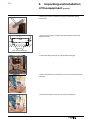
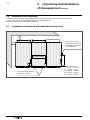
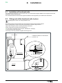
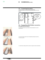
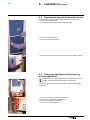
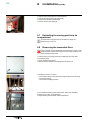
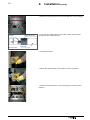
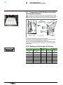
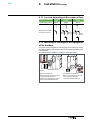
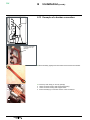
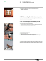
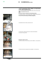
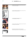
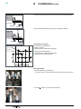
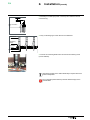
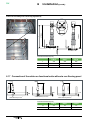
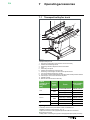
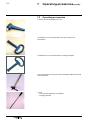
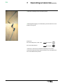
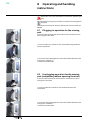
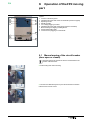
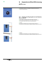
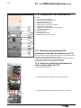
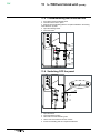
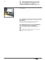
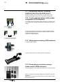
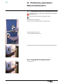
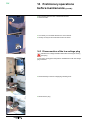
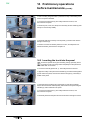
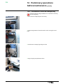
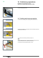
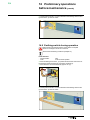
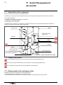
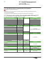
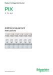
PIX
6
70
Installation (contd.)
■■ Assembly and tightening of the 4 screws (10 mm Allen key).
□□ busbar : 45 mm screw,
□□ busbars : 55 mm screw.
6.14 Remounting the internal arcing valves
At the end of this work, proceed with re-assembly in the reverse order to the
operations described above (see § 6.9).
6.15 Connecting up the earthing circuit
■■ To connect two functional units together:
1 Unscrew the bolt H M8x35 (13 mm spanner) retaining the busbar link.
2 Slide this link through the functional units flange.
16
1
2
16
3
4
■■ In the adjacent functional unit:
■■ Unscrew the fixing screw.
3 Adjust the busbar link with the aid of slotted holes.
4 Bolt the busbar link on the 2 sides and tighten to indicated torque.
■■ Connect the earthing circuit linking all of the functional units to the room’s
earthing bar (Threaded fasteners H M12 and earthing cables not supplied).
49
AMTNoT056-02
31