1
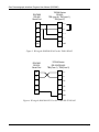
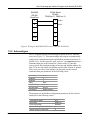
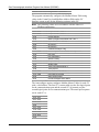
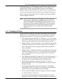
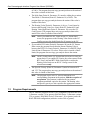
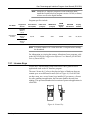
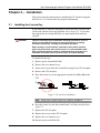
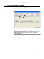
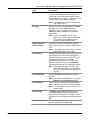
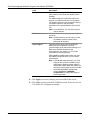
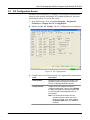
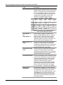
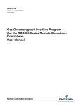
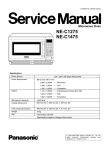
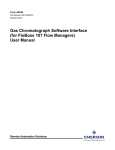
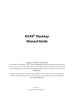
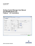
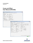
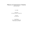
Form A6145 Part Number D301188X012 September 2013 Gas Chromatograph Interface Program User Manual (for the ROC800-Series Remote Operations Controllers) Remote Automation Solutions Gas Chromatograph Interface Program User Manual (ROC800) Revision Tracking Sheet September 2013 This manual may be revised periodically to incorporate new or updated information. The revision date of each page appears at the bottom of the page opposite the page number. A change in revision date to any page also changes the date of the manual that appears on the front cover. Listed below is the revision date of each page (if applicable): Page All pages All pages All pages All pages All pages All pages All pages All pages All pages All pages Initial release ii Revision Sep-13 Dec-12 Jul-12 Mar-09 Jul-08 May-08 Sep-07 Jul-06 Dec-05 May-05 Jul-03 Rev. Sep-13 Gas Chromatograph Interface Program User Manual (ROC800) Contents Chapter 1 – Introduction 1-1 1.1 Scope and Organization ................................................................................................................. 1-1 1.2 Product Overview ........................................................................................................................... 1-1 1.3 1.2.1 Communications Wiring.................................................................................................. 1-2 1.2.2 Autoconfigure ................................................................................................................. 1-5 1.2.3 Validating GC Data ......................................................................................................... 1-7 Program Requirements................................................................................................................... 1-8 1.3.1 License Keys .................................................................................................................. 1-9 Chapter 2 – Installation 2.1 Installing the License Key ............................................................................................................... 2-1 2.1.1 2.2 2-1 Verifying the License Key Installation............................................................................. 2-2 Downloading the Program .............................................................................................................. 2-3 Chapter 3 – Configuration 3-1 3.1 GC Interface Screen ....................................................................................................................... 3-2 3.2 GC Configuration Screen................................................................................................................ 3-5 3.3 GC Stream Data Screen ................................................................................................................. 3-7 3.4 Station Setup, Gas Quality Tab .................................................................................................... 3-11 3.5 Saving the Configuration .............................................................................................................. 3-12 Chapter 4 – Reference 4-1 4.1 Point Type 65: GC User Program Configuration and Status .......................................................... 4-2 4.2 Point Type 66: GC Stream Data ................................................................................................... 4-10 Rev. Sep-13 iii Gas Chromatograph Interface Program User Manual (ROC800) [This page is intentionally left blank.] iv Rev. Sep-13 Gas Chromatograph Interface Program User Manual (ROC800) Chapter 1 – Introduction This chapter describes the structure of this manual and presents an overview of the Gas Chromatograph Interface Program for the ROC800Series (ROC800) Remote Operations Controllers. 1.1 Scope and Organization This document serves as the user manual for the Gas Chromatograph Interface program, which is intended for use in a ROC800. This manual describes how to download, install, and configure the Gas Chromatograph Interface user program (referred to as the “GC Interface program” or “the program” throughout the rest of this manual). You access and configure this program using ROCLINK 800 Configuration Software loaded on a personal computer (PC) running Windows® 2000 (with Service Pack 2), Windows XP (with Service Pack 3), Windows Vista (32-bit), or Windows 7 (32-bit). The sections in this manual provide information in a sequence appropriate for first-time users. Once you become familiar with the procedures and the software, the manual becomes a reference tool. This manual has the following major sections: Chapter 1 – Introduction Chapter 2 – Installation Chapter 3 – Configuration Chapter 4 – Reference This manual assumes that you are familiar with the ROC800 and its configuration. For more information, refer to the following manuals: 1.2 ROC800-Series Remote Operations Controller Instruction Manual (Form A6175) ROCLINK 800 Configuration Software User Manual (for RO800Series) (Form A6218) Product Overview The GC Interface program enables the ROC800 to communicate directly with one gas chromatograph (GC) on an EIA-232 (RS-232) or up to two GCs on an EIA-485 (RS-485) communications port. Supported gas chromatographs include the Rosemount Analytical (including Danalyzer) Model 500 series, Model 700 series, Model 1000/1000A series, 370XA, 700XA series, and 1500XA series. This includes the associated 2251, 2350, 2350A, and 2360 controllers. Rev. Sep-13 1-1 Gas Chromatograph Interface Program User Manual (ROC800) The program communicates directly with the GC using Modbus protocol (in which the ROC800 has Master status). The ROC800 polls data from the GC, validates that data, and updates the appropriate station parameters using that data. The program can poll up to eight GC streams on one GC or up to a total of ten streams on two GCs. The total number of streams the program can process may be limited by the number of stream licenses available in the ROC800. This value is listed in the App Code field on the License Key Administrator screen (Utilities > License Key Administrator) in ROCLINK 800. Refer to Section 2.1.1 for further information on the ROC800 license keys. The program assigns a type of gas or liquid for each GC supported. This allows the program to write GC data to either gas stations (for measurement of natural gas or related hydrocarbon gases) or liquid stations when used with a ROC800L (for measurement of light hydrocarbon liquids). In order to update station data in the ROC800, you must assign the streams to gas or liquid station(s) in the database of the ROC800. In the case of gas, this allows the ROC800 to log the gas component data, heating value, and specific gravity and use these values in volume, mass, and energy calculations. In the case of liquid, this allows the ROC800L to use the fluid component data to calculate the mass, volume and density of the measured product. 1.2.1 Communications Wiring The GC must be connected to the communications port on the ROC800 using 12 AWG (or smaller) wire. Figure 1 shows the wiring for an EIA232 (RS-232) to a 2350A GC. 1-2 Rev. Sep-13 Gas Chromatograph Interface Program User Manual (ROC800) ROC800 RS-232 Serial Port 2350/2350A Controller RS-232 J5 (port 1), J6 (port 2), J10 (port 3), J11 (port 4) 1 Rx 2 S OUT Tx 3 S IN RTS 4 DTR 5 GND 6 GND Figure 1. Wiring the ROC800 RS-232 to the 2350/2350A Controller ROC800 RS-232 Serial Port 700XA Series RS-232 TB1 (port 0), TB5 (port 1), TB8 (port 2) Rx 1 Rx + Tx 2 Tx + RTS 3 RTS DTR 4 GND GND Figure 2. Wiring the ROC800 RS-232 to the 700XA RS-232 Rev. Sep-13 1-3 Gas Chromatograph Interface Program User Manual (ROC800) 700XA Series RS-485 TB2 (port 0), TB6 (port 1), TB9 (port 2) A 1 Rx + B 2 Rx - Y 3 Tx + Z 4 Tx - COM 5 GND 120Ω ROC800 RS-485 Serial Port Figure 3. Wiring the ROC800 RS-485 to the 700XA RS-485 ROC800 RS-232 Serial Port 370XA Series RS-232/RS-485 TB4(Com 1), TB9(Com 2) RX 1 Rx + TX 2 Tx + RTS 3 RTS DTR 4 CTS GND 5 DTR 6 GND Figure 4. Wiring the ROC800 RS-232 to the 370XA RS-232/RS-485 1-4 Rev. Sep-13 Gas Chromatograph Interface Program User Manual (ROC800) ROC800 RS-485 Serial Port 370XA Series RS-485 TB4(Com 1), TB9(Com 2) A 1 TX/Rx + B 2 Tx/RX - Y 3 Z 4 COM 5 6 GND Figure 5. Wiring the ROC800 RS-485 to the 370XA RS-232/RS-485 1.2.2 Autoconfigure The GC Program provides an autoconfigure option on the GC Interface screen (see Figure 17). This option enables the program to automatically configure the communication ports and Modbus parameters necessary to poll the GC(s). For this option to work, however, you must first specify a communication port in the Comm Port # frame on the GC Interface screen, specify the maximum number of streams and Modbus address for each GC in use, and modify the Modbus register table location, if desired. Then, when you select Autoconfigure, the program sets the selected communication port parameters to the following values: Baud Rate Data Bits Stop Bits Parity Key-On Delay Key-Off Delay Port Owner 9600 8 1 None 200 ms 200 ms Modbus Master The program sets the Modbus configuration parameters for the selected comm port to the following values: Transmission Mode Byte Order Event Log Enable Master Starting Request Number Master Number of Requests Rev. Sep-13 RTU MSB First Disabled 1 8 1-5 Gas Chromatograph Interface Program User Manual (ROC800) Master Continuous Polling Enable Disabled The program automatically configures the Modbus Master Table using values in the Comm Port # and Modbus Address fields on the GC Interface screen to poll for the following registers in the GC: Note: The following values are in accordance with the SIM 2251 Modbus register map. 3001–3016 3017–3032 3034 3035 3045 3046 3047 3059 7001–7016 7033 7034 7035 7036 7037 7038 7039 7040–7044 7070–7084 9034 9035 Component IDs, Table 1 Component IDs, Table 2 Current Stream Mask of Streams associated with Table 1 Cycle Start Time – minutes GC Alarm 1 GC Alarm 2 Calibration/Analysis Flag Gas Composition Values Mole % Comp 1–16 BTU (dry) BTU (saturated) Specific Gravity Compressibility Wobbe Index Total Unnormalized Mole % Total GPM CF User Defined Calc Values User Defined Average Active Alarm Status Unacknowledged Alarm Status The Autoconfigure option configures Modbus Master Tables for each GC with a valid address. The first GC’s master table uses the first logical point for the communications port and the second GC (if present) uses the second logical point for its communications port. The actual poll sequence set for each GC is: 3045–3047 3001–3032 3034–3035 3059 7001–7016 7033–7044 7070–7084 9034–9035 3045 1-6 Rev. Sep-13 Gas Chromatograph Interface Program User Manual (ROC800) The Modbus Register to TLP Mapping assigns TLPs to registers. The program maps TLPs to the register table you specify in the Modbus Register Table Location field on the GC Interface screen. The parameters necessary for this program automatically map to the appropriate registers. Finally, when the autoconfigure process completes, the program disables the autoconfigure parameter. Note: After the autoconfigure process completes, you may modify the Modbus Master Table and/or the Modbus Register Table, but register 3045 must be the first and last register polled. The first poll must be stored in a register mapped to GC Stream parameter Sample Min Start (66,0,17) and the last poll must be stored in a register mapped to GC Stream parameter Sample Min End (66,0,16). 1.2.3 Validating GC Data When the polls are complete, the program validates the data to ensure the polling was successful and data is correct. This validation occurs before the program copies the GC stream data to the station. Checks include: Rev. Sep-13 The Communication Status (Point 121, Parameter 6, 12, 18, etc.) must return valid responses (value of 8) for all registers polled. The program does not copy gas analysis data to the station if errors are present. If Bypass Alarm 1 (Point 65, Parameter 11) is disabled, the Alarm Flag 1 (Point 66, Parameter 18, bits 14 & 15) from the GC is checked for errors. The program does not copy gas analysis data to the station if errors are present. If Bypass Alarm 2 (Point 65, Parameter 12) is disabled, the Alarm Flag 2 (Point 66, Parameter 19, bits 0, 1, 2 & 3) from the GC is checked for errors. The program does not copy gas analysis data to the station if errors are present. The Calibration Flag (Point 66, Parameter 20) is checked to ensure it is in the Analysis State. The program does not copy gas analysis data to the station if the Calibration Flag is not in the Analysis State. The Starting Sample Minute (Point 66, Parameter 17) must be different than the previous or the program does not copy gas analysis data to the station. The Starting Sample Minute (Point 66, Parameter 17) and Ending Sample Minute (Point 66, Parameter 16) in the poll must match or the program does not copy gas analysis data to the station. The current Stream Number (Point 66, Parameter 2) must be assigned to a station and have a license key. The Total Un-Normalized Mole % (Point 66, Parameter 9) must be within plus or minus Total Mole % Deviation (Point 65, Parameter 14) 1-7 Gas Chromatograph Interface Program User Manual (ROC800) of 100%. The program does not copy gas analysis data to the station if the value is outside of this limit. The Mole Sum (Point 66, Parameter 21) must be within plus or minus Total Mole % Deviation (Point 65, Parameter 14) of 100%. The program does not copy gas analysis data to the station if the value is outside of this limit. The Heating Value [Point 66, Parameter 4 (dry) or 5 (wet)] must be between the Heating Value Low Limit (Point 65, Parameter 9) and Heating Value High Limit (Point 65, Parameter 10) set on the GC Config screen. The program does not copy gas analysis data to the station if the value is outside of these limits. Note: Unless you enable the HV Limits on the GC Stream Data screen, the program uses the Heating Value limits on the GC Config screen as the global limits for all streams in the GC. If you enable HV Limits (Point 66, Parameter 90) on the GC Stream Data screen, the program checks that the Stream Heating Value is between the BTU Low Limit (Point 66, Parameter 91) and BTU High Limit (Point 66 Parameter 92) values. If this value is outside of these limits, the program does not copy gas analysis data to the station. Note: The HV Limits on the GC Stream Data screen are set on a per- stream basis. If you enable HV Limits, the values entered in the BTU Low Limit and BTU High Limit fields overrides the Heating Value limits set on the GC Config screen for the selected stream only. The Specific Gravity (Point 66, Parameter 6) must be between 0.07 and 1.52. The program does not copy gas analysis data to the station if this value is outside of the limits. Note: The program copies each GC stream component to its corresponding component in the station, with the exception of neo-pentane. Neo-pentane is added to the iso-pentane component and then copied to the station. The heating value and specific gravity are also copied to the appropriate station. 1.3 Program Requirements The GC Interface program version 2.10 is compatible with ROC800 Series 1 (firmware version 2.16 or greater), ROC800 Series 2 (firmware version 3.30 or greater), ROC800L Series 2 (Firmware 1.20 or greater), and with ROCLINK 800 configuration (software version 2.00 or greater). 1-8 Rev. Sep-13 Gas Chromatograph Interface Program User Manual (ROC800) Note: When the GC Interface program is used on the ROC800L, install the LiquidCalcs user program version 1.03.00 (or better) to have access to the liquid stations. Program specifics include: File Name Target Unit/ Version User Defined Point (UDP) Flash Used (in bytes) SRAM Used (in bytes) DRAM Used (in bytes) ROCLINK 800 Version Display Number 65, 66 53340 2972 94208 2.00 65, 66, 67 ROC800 Series 1 v2.16 GcInterface2-10.tar ROC800 Series 2 v3.30 ROC800L Series 2 v1.20 Note: You must connect a PC to the ROC800’s LOI port before starting the download. For information on viewing the memory allocation of user programs, refer to the ROCLINK 800 Configuration Software User Manual (for ROC800Series) (Form A6218). 1.3.1 License Keys License keys, when matched with valid license codes, grant access to applications such as the GC Interface program. The term “license key” refers to the physical piece of hardware that can contain up to seven different licenses (refer to Figure 6). Each ROC800 can have none, one, or two license keys installed. If you remove a license key after enabling an application, the firmware disables the task from running. This prevents unauthorized execution of protected applications in a ROC800. J1 U1 DOC0422A Figure 6. License Key Rev. Sep-13 1-9 Gas Chromatograph Interface Program User Manual (ROC800) You must install the following license keys to use the GC Interface Program. 1-10 GC Interface License Key. AGA_3/7/8 License Key (not included in this program). Rev. Sep-13 Gas Chromatograph Interface Program User Manual (ROC800) Chapter 2 – Installation This section provides instructions for installing the GC Interface program. Read Section 1.3 of this manual for program requirements. 2.1 Installing the License Key If you order the GC Interface program for a new ROC800, your ROC800 is delivered with the license key installed. Go to Section 2.2. If you order the program for an existing ROC800, you must install the license key yourself. Caution Failure to exercise proper electrostatic discharge precautions, such as wearing a grounded wrist strap may reset the processor or damage electronic components, resulting in interrupted operations. When working on units located in a hazardous area (where explosive gases may be present), make sure the area is in a non-hazardous state before performing these procedures. Performing these procedures in a hazardous area could result in personal injury or property damage. To install a license key: 1. Remove power from the ROC800. 2. Remove the wire channel cover. 3. Unscrew the screws from the Central Processing Unit (CPU) faceplate. 4. Remove the CPU faceplate. 5. Place the license key in the appropriate terminal slot (P4 or P6) in the CPU. Figure 7. License Key Installation Note: When using a single license key, install it in slot P4. 6. Press the license key into the terminal until it is firmly seated (refer to Figure 7). 7. Replace the CPU faceplate. 8. Replace the screws on the CPU faceplate. 9. Replace the wire channel cover. 10. Restore power to the ROC800. Rev. Sep-13 2-1 Gas Chromatograph Interface Program User Manual (ROC800) 2.1.1 Verifying the License Key Installation After you install the license key, you can verify whether the ROC800 recognizes the key. From the ROCLINK 800 screen, select Utilities > License Key Administrator. The License Key Administrator screen displays: Figure 8. License Key Administrator The GC Interface program appears in the Application Name column. [For further information on the License Key Administrator screen, refer to the ROCLINK 800 Configuration Software User Manual (for ROC800Series), Form A6218]. Note: The value in the App Code field on this screen indicates the total number of stream licenses available on this ROC800. After you verify that the license key is correctly installed and recognized, proceed to Section 2.2. 2-2 Rev. Sep-13 Gas Chromatograph Interface Program User Manual (ROC800) 2.2 Downloading the Program This section provides instructions for installing the program into the Flash memory on the ROC800. To download the program using ROCLINK 800 software: 1. Connect the ROC to your computer using the LOI port. 2. Start and logon to ROCLINK 800. 3. Select Utilities > User Program Administrator from the ROCLINK menu bar. The User Program Administrator screen displays (see Figure 9). Figure 9. User Program Administrator 4. Select any empty program number (in this case, number 1) into which to download the program. 5. Click Browse in the Download User Program File frame. The Select User Program File screen displays (see Figure 10). 6. Select the path and user program file to download from the CD-ROM. (Program files are typically located in the Program Files folder on the CD-ROM). As Figure 10 shows, the screen lists all valid user program files with the .TAR extension. Rev. Sep-13 2-3 Gas Chromatograph Interface Program User Manual (ROC800) Figure 10. Select User Program File 7. Click Open to select the program file. The User Program Administrator screen displays. As shown in Figure 11, note that the Download User Program File frame identifies the selected program and that the Download & Start button is active. Figure 11. User Program Administrator 2-4 Rev. Sep-13 Gas Chromatograph Interface Program User Manual (ROC800) 8. Click Download & Start to begin loading the selected programs. The following message displays: Figure 12. Confirm Download 9. Click Yes to begin the download. When the download completes the following message displays: Figure 13. ROCLINK 800 Download Confirmation 10. Click OK. The User Program Administrator screen displays (see Figure 14). Note that: Rev. Sep-13 The Device User Program Environment frame reflects the use of system memory. The User Programs Installed in Device frame identifies the installed program(s). The Status field indicates that the program is running. 2-5 Gas Chromatograph Interface Program User Manual (ROC800) Figure 14. User Program Administrator 11. Click Close. The ROCLINK 800 screen displays and the download is complete. Figure 15. ROCLINK 800 2-6 Rev. Sep-13 Gas Chromatograph Interface Program User Manual (ROC800) Chapter 3 – Configuration After you have loaded the GC Interface program on the ROC800, you configure the program using three program-specific screens (GC Interface, GC Configuration, and GC Stream Data) and one ROCLINK 800 screen (Station Setup). You must configure the software before you can establish communications with the GC. To configure the program (after logging onto ROCLINK 800 and successfully installing the program and license key), proceed through the program screens as shown in this section. Note: Using MON 2000 software, you set the GC communications port to the SIM 2251 protocol. For all other parameter configurations, refer to the MON 2000 documentation. You can access all the program-specific screens from the main ROCLINK 800 screen: Figure 16. ROCLINK 800 Rev. Sep-13 3-1 Gas Chromatograph Interface Program User Manual (ROC800) 3.1 GC Interface Screen Use this screen to configure one or more GC addresses, select a Comm port, modify the Modbus Register Table location (if necessary), assign the GC streams to stations, enable GC polling, and enable automatic configuration of the Modbus parameters and communications ports. To access this screen: 1. From the Directory Tree, select User Program > Program #1, GcInterface. 2. Double-click Display #65, GC Interface. The GC Interface screen displays: Figure 17. GC Interface 3. Review the values in the following fields: 3-2 Field Description Max Streams Sets the maximum number of streams from the gas chromatograph. Valid values are 1 through 8, depending on your license. You cannot define more than 10 streams for both GCs. Note: Your license limits the maximum number of allowable streams for one or both GCs. See Section 2.1.1 for instructions on determining the maximum number of allowable streams. Rev. Sep-13 Gas Chromatograph Interface Program User Manual (ROC800) Rev. Sep-13 Field Description Modbus Address Sets the address the ROC800 uses to communicate with the gas chromatograph. You must set this value before the program can poll data and write it to the station. If you set this field to 0 (the default), GC polling is disabled. Note: The Autoconfigure option uses this value (see Section 1.2.2). GC Type Sets the GC Type. The available types are Gas or Liquid. If you select Gas, the program updates the gas components. If you select Liquid, the program updates the LiquidCalcs components. Note: If you select Liquid, only the first 6 stations of the station map are applicable. The program ignores assignments of streams to stations greater than 6. Modbus Register Table Location Identifies the location of the Modbus Register Table. Valid values are 1–24. The default value is 24. Note: The program uses this value for automatic configuration (see Section 1.2.2). Comm Port # Indicates which ROC800 communications port the program uses for the EIA-232 (RS-232) or EIA-485 (RS-485) connection to the GC(s). The program uses this value for automatic configuration (see Section 1.2.2). Click to display all valid values. If you select Ethernet, the program displays an IP configuration section. Note: Unlike other programs, the Comm Port owner is Modbus Master. For that reason, the Comm Port owner should not be this program. IP Configuration Sets the IP address and IP port connected to the GCs. Note: This section is available only if you select Ethernet as the Comm Port # value. Polling Interval Sets the delay, in seconds, the program waits before asking the GC for the next set of results. Note: The GC typically takes 3 to 6 minutes to update results. Next Poll Req This display-only field shows the number of seconds remaining until the next polling cycle. After a poll cycle completes, the program resets this field to the value stored in the Polling Interval field. Comm Timeout Sets the period, in seconds, the system waits for the GC to respond to a Modbus poll. 3-3 Gas Chromatograph Interface Program User Manual (ROC800) Field Description Station Map Associates GC streams with ROC800 stations. Valid values are 1–8. Enter 0 to disable station updating. You must configure this parameter before the program can poll data and write it to the station. The program stores the gas composition data for the specified stream in the gas quality parameters of the specified station (see Section 3.4). Note: For a ROC800L, you can select only the first six stations. Poll Mode Indicates whether the program attempts to poll the GC(s). Note: A valid license key and at least one valid GC address must be present before polling can be enabled. Autoconfigure Indicates whether the program automatically determines the configuration values for communications ports and Modbus settings for a Rosemount Analytical Danalyzer gas chromatograph. See Section 1.2.2 for further information on autoconfiguration. Polling must be disabled and at least one valid GC address configured before you can initiate Autoconfigure. Note: If you do not select this option, you must configure the comm port, Modbus comm configuration, Modbus register mapping, and Modbus master table. Alternately, you can select Autoconfigure and then use the ROCLINK 800 Modbus Configuration screen (Configure > MODBUS > Configuration) to change the values to suit the application. 4. Click Apply to save any changes you have made to this screen. 5. Click Close to return to the ROCLINK 800 screen. Proceed to Section 3.2 to define GC configuration settings. 3-4 Rev. Sep-13 Gas Chromatograph Interface Program User Manual (ROC800) 3.2 GC Configuration Screen Use this screen to configure GC settings. It also displays communication status for each polling, configurable AGA update parameters, and some returned data values. To access this screen: 1. From the Directory Tree, select User Program > Program #1, GcInterface > Display #66, GC Configuration. 2. Double-click #1, GC Config1. The GC Configuration screen displays: Figure 18. GC Configuration 3. Complete the screen fields based on your organization’s requirements. Rev. Sep-13 Field Description Point Number Identifies the GC number for this screen. The program provides one instance for each GC. Click to display all defined instances. Component IDs Assigns each gas component a value in component data tables 1 and 2. Select Disable to identify any gases the ROC800 supports but for which the gas chromatograph does not provide data. Note: The Hexane and Hexane+ IDs are mutually exclusive. Select one or the other but not both. If you have enabled the Hexane Split option, you must use Hexane+. 3-5 Gas Chromatograph Interface Program User Manual (ROC800) Field Description Hexane Split Enable Enables the hexane(+) composition to be split between hexane, heptane, octane, nonane, and decane. The program uses a pre-defined split if the component ID for hexane(+) is set to 8, 9, 10, or 11 (see table below). For any other valid component ID, the program uses the split specified on the Station Setup screen’s Advanced tab (Meter > Setup > Station). ID Hexane % Heptane % Octane % Nonane % Decane % 8 47.466 35.34 17.194 0 0 9 50 50 0 0 0 10 50 25 25 0 0 11 57.143 28.572 14.285 0 0 Note: The ID selection for a ROC800 must match the ID selection for the GC. 3-6 Alarm Bypass 1 and Alarm Bypass 2 Sets whether the program updates station values in the ROC800 if the Alarm 1 or Alarm 2 field on the GC contains an alarm condition. Select this check box to allow the program to update the station values even if the Alarm 1 or Alarm 2 field in the GC displays an alarm. Heating Value Low Limit Sets the minimum heating value the ROC800 accepts for a station update. The ROC800 considers any heating values the GC sends that are lower than this value to be erroneous and does not forward them to the station. Heating Value High Limit Sets the maximum heating value the ROC800 accepts for a station update. The ROC800 considers any heating values the GC sends that are greater than this value to be erroneous and does not forward them to the station. Total Mole Deviation Sets, as a percentage, either the difference plus or minus from 100% that the program allows for Total Unnormalized Mole % or the sum of the component mole percentages. The program subtracts or adds this value to 100% to determine the range. The ROC800 considers any stream gas compositions that exceed this value to be erroneous and does not forward them to the station. Valid values are 0-100%. Heating Value Adjustment Sets whether the program (in case of differing base pressures between the GC and the station point) adjusts the GC’s heating value before storing the value in the station parameter. If you click Enable, the heating value stored in the station equals the GC heating value multiplied by the ratio of the station base pressure to the GC’s base pressure. Rev. Sep-13 Gas Chromatograph Interface Program User Manual (ROC800) Field Description GC Base Pressure Sets the base pressure, in PSIA or kPa, the GC uses to determine the heating value that is returned on a Modbus request. Note: This field is active only if you enable the Heating Value Adjustment. 4. Click Apply to save your changes. 5. Click Close to return to the ROCLINK 800 screen. Proceed to Section 3.3 to review stream data. 3.3 GC Stream Data Screen Use this screen to review stream data the ROC800 has received from the GC(s). The program provides one iteration of this screen for each active stream in each GC. You can move between stream data displays using either the Point Number drop-down box on this screen or from the list on the Directory Tree. With the exception of the Alarm Logging Mode and HV Limits, the fields on this screen are display-only. To access this screen: 1. From the Directory Tree, select User Program > Program #1, GcInterface > Display #67, GC Stream Data. 2. Double-click #1, Cur Stream. The GC Stream Data screen displays: Figure 19. GC Stream Data Rev. Sep-13 3-7 Gas Chromatograph Interface Program User Manual (ROC800) 3. Review—and change as necessary—the values in the following fields: 3-8 Field Description Point Number Identifies the stream number for this screen. Click to display all defined streams. Calibration/Analysis Flag This read-only field indicates the chromatograph’s status (self-calibration or analysis). HV Limits Select the Enable checkbox to allow userdefined Heating Value (HV) limits to be set for the selected run. If the HV Limits are enabled, the BTU Low/High values for the selected run will override the Heating Value High/Low Limits set on the GC Configuration screen. BTU Low Limit Sets the minimum heating value for the selected run that the ROC800 accepts for a station update. The ROC800 considers any heating values the GC sends that are greater than this value to be erroneous and does not forward them to the station. Note: Values entered in this field override the Heating Value Low Limits set on the GC Configuration screen for the selected run only. BTU High Limit Sets the maximum heating value for the selected run that the ROC800 accepts for a station update. The ROC800 considers any heating values the GC sends that are greater than this value to be erroneous and does not forward them to the station. Note: Values entered in this field override the Heating Value High Limits set on the GC Configuration screen for the selected run only. Stream This read-only field identifies the defined stream for the GC. Stream Data This read-only field shows values for the selected stream. Component Data This read-only field shows component values for the selected stream. User Defined Averages This read-only field shows historical averages for the selected stream. User Calcs This read-only field identifies any user-defined calculations for the selected stream. Rev. Sep-13 Gas Chromatograph Interface Program User Manual (ROC800) Rev. Sep-13 Field Description Diagnostics This read-only field shows any diagnostic codes for the selected stream. Component Mask This read-only field shows which of the two Component ID tables each stream uses. Bit 0 of the Component Mask represents stream 1, bit 1 represents stream 2, and so on. If the bit is set, the program uses Component ID table 1. If the bit is not set, the program uses Component ID table 2. Note: This value reflects settings from the GC. Error Code This read-only field provides a color-coded error display. Red indicates an alarm condition. Note: Error code changes are logged in the Event Log as UDP66. Error code entries in the Event Log are the numerical values shown in parenthesis. OK (0) All checks passed. Poll Seq Fail (1) Poll Sequence Failure – One or more master table requests were unsuccessful (not an 8). Alarm Fail (2) Alarm Check Failure – There are non-bypassed alarms in effect. Cal Flag Fail (3) Calibration Check Failure – The unit is in calibration mode. Sample Min Change (4) Sample Minute Changed – The sample minute changed while collecting data. Unnorm Mole % Fail (5) Total Un-Normalized % Failure – The total un-normalized mole percentage is not within range. Mole Sum Fail (6) Mole Sum Check Failure – The mole sum is not within the range. Heat Val Range Fail (7) BTU Range Failure – BTU is not within specified ranges. Spec Grav Range Fail (8) Specific Gravity Range Failure – Specific gravity is not within specified ranges. 3-9 Gas Chromatograph Interface Program User Manual (ROC800) Field Description Alarm Logging Mode Indicates how the program logs alarms with Spontaneous Report by Exception (SRBX) notification. Click to select a mode (described below). Note: The system generates one alarm, regardless of the number of different errors that may occur in the time before the alarm clears. SRBX notification occurs based on the Alarm Logging Mode. For the system to generate an alarm (such as for a Poll Sequence Failure error), you must first enable the Alarm Logging Mode parameter on the current logical stream. Disable Logging No logging occurs. Enable Logging, No SRBX Logging occurs, but without generating SRBX notifications. Enable Logging, SBRX in Set Logging occurs, and SRBX notifications occur on alarm set. Enable Logging, SRBX on Clear Logging occurs, and SRBX notifications occur on alarm clear. Enable Logging, SRBX on Both Logging occurs, and SRBX notifications occur on both alarm set and alarm clear. Minimum Specific Gravity The user entered minimum specific gravity for the selected stream. Note: This field applies only to the currently selected stream. Maximum Specific Gravity The user entered maximum specific gravity for the selected stream. Note: This field applies only to the currently selected stream. 4. Click Apply to save your changes. 5. Click Close to return to the ROCLINK 800 screen. Proceed to Section 3.4 to set up station parameters. 3-10 Rev. Sep-13 Gas Chromatograph Interface Program User Manual (ROC800) 3.4 Station Setup, Gas Quality Tab Use this screen to set gas quality and heating values. To access this screen: 1. Select Meter > Setup > Station from the ROCLINK 800 menu bar. The Station Setup screen displays. Figure 20. Station Setup, Gas Quality tab 2. Select the Gas Quality tab. 3. Review—and change as necessary—the values in the following fields: Rev. Sep-13 Field Description Station Select the station number to which the GC stream has been assigned. Gas Quality Indicates source of the gas quality. The GC Interface program sets this field to Live when it copies data to the station. Heating Value Basis Determines the heating value (dry or saturated) the program copies to the station. Valid values for this program are Dry or Wet. If you select Wet, the program copies the saturated heating value to the station. If you select As Deliv or Dry, the program resets the value to Dry and copies the dry heating value to the station. 3-11 Gas Chromatograph Interface Program User Manual (ROC800) Field Description Heavy Gas Option Permits calculations for hexane and other heavy gases. Note: The program automatically selects this option if you checked the Hexane Split Enable option on the GC Configuration screen. 4. Click Apply to save your changes. Proceed to Section 3.5 to save the configuration. 3.5 Saving the Configuration Whenever you modify or change the configuration, it is a good practice to save the final configuration to memory. To save the configuration: 1. Select ROC > Flags. The Flags screen displays: Figure 21. Flags screen 2. Click Save Configuration. A verification message displays: Figure 22. Perform screen 3-12 Rev. Sep-13 Gas Chromatograph Interface Program User Manual (ROC800) 3. Click Yes to begin the save process. The Flash Write Status field on the Flags screen displays In Progress. When the process ends, the Flash Write Status field on the Flags screen displays Completed. 4. Click Update on the Flags screen. This completes the process of saving your new configuration. Note: For archive purposes, you should also save this configuration to your PC’s hard drive or a removable media (such as a flash drive) using the File > Save Configuration option on the ROCLINK 800 menu bar. Rev. Sep-13 3-13 Gas Chromatograph Interface Program User Manual (ROC800) [This page is intentionally left blank.] 3-14 Rev. Sep-13 Gas Chromatograph Interface Program User Manual (ROC800) Chapter 4 – Reference This section provides tables of information on the user-defined point types used by the GC Interface program. Rev. Sep-13 Point Type 65: GC User Program Configuration and Status Point Type 66: GC Stream Data 4-1 Gas Chromatograph Interface Program User Manual (ROC800) 4.1 Point Type 65: GC User Program Configuration and Status Point type 65 contains the parameters for configuring the GC Interface program and houses the status information from the gas chromatograph. The program maintains two logical points of this point type. 4-2 Parm # Name Abbrev. Access Program or User Update Data Type Length Range Default Version 0 Point Tag ID Tag R/W User AC 10 0x20 → 0x7E for each ASCII character “GC Config“ 1.00 Identification name for the GC Program. Values must be printable ASCII characters. 1 Point Version Number Version R/O User U32 4 0→0xFFFFFFFF 1 1.00 Version number of this user defined point. Version number of user defined point must match version of user program for calculation to run. 2 User Program Status Status R/O Program UINT8 1 0→3 0 1.00 Indicates running status. 0: No Error 1: License Unavailable 2: Comm Configuration Failed 3: Bad Point Type Version 3 Autoconfiguration Autoconf R/W Both UINT8 1 0→1 1 1.00 Sets autoconfiguration option 0: Autoconfiguration disabled 1: Autoconfiguration enabled 4 Comm Port Number CommPort R/W User UINT8 1 15 2 1.00 Comm Port to be used 5 GC Address GcAddr R/W User UINT8 1 0255 0 1.00 The Modbus address for the GC. A zero disables polling. The GC Address parameter only configures the Modbus Master Table when autoconfiguration is enabled. 6 MODBUS Location Locatn R/W User UINT8 1 124 24 1.00 This is the location to which the Modbus registers are configured (Logical + 1) Description of functionality and meaning of values Rev. Sep-13 Gas Chromatograph Interface Program User Manual (ROC800) Parm # Name Abbrev. Access Program or User Update Data Type Length Range Default Version 7 Polling Interval PollInt R/W User FL 4 Any Positive Floating Point Number 60 1.00 Amount of delay in seconds before asking for next set of results. The GC typically takes 3 to 6 minutes to update the results. 8 Next Poll Request PollNext R/O Program FL 4 Any Positive Floating Point Number 0 1.00 Displays the number of seconds remaining until the next polling cycle. After a poll cycle is complete, this field is preset to the number stored in the Poll Interval Parameter. 9 Heating Value Low Limit BtuLow R/W User FL 4 Any Floating Point Number 900.0 1.00 This is the minimum heating value accepted by the ROC for a n AGA update. Heating values sent by the GC which are less than this number are considered to be erroneous and will not be forwarded to the ROC. 10 Heating Value High Limit BtuHi R/W User FL 4 Any Floating Point Number 1300.0 1.00 This is the maximum heating value accepted by the ROC for an AGA update. Heating values sent by the GC which are less than this number are considered to be erroneous and will not be forwarded to the ROC. 11 Bypass Alarm 1 BypAl1 R/W User UINT8 1 01 0 1.00 Indicates how to interpret alarm 1 value. 0: Disable bypass – Don’t populate the AGA gas composition information if an “Alarm 1” is present. 1: Enable bypass – Allow the ROC AGAs to be updated even if the “Alarm 1” field in the GC shows an alarm condition present. Rev. Sep-13 Description of functionality and meaning of values 4-3 Gas Chromatograph Interface Program User Manual (ROC800) 4-4 Parm # Name Abbrev. Access Program or User Update Data Type Length Range Default Version 12 Bypass Alarm 2 BypAl2 R/W User UINT8 1 01 0 1.00 Indicates how to interpret alarm 2 value. 0: Disable bypass – Don’t populate the AGA gas composition information if an “Alarm 2” is present. 1: Enable bypass – Allow the ROC AGAs to be updated even if the “Alarm 2” field in the GC shows an alarm condition present. 13 Max Streams MaxStrm R/W User UINT8 1 0255 6 1.00 Maximum number of GC stream licenses to check out for this program. 14 Total Mole % Deviation Deviat R/W User FL 4 0100.0 2.0 1.00 The difference plus or minus from 100% that is allowable for both Total Unnormalized Mole % and mole sum values. Default is 98%-102%. 15 Hexane Split Enable C6+Ena R/W User UINT8 1 01 1 1.00 Enables the GC’s automatic C6 (+) split percentage for heavy gasses. 16 Communication Timeout Timeout R/W User FL 4 060.0 45.0 1.00 Time to wait in seconds for the GC to respond to all Modbus Polls. 17 Station 1 Stream Stn1Stm R/W User UINT8 1 08 0 1.00 Stream data to be used to update station #1. 0: Disable updating of station. 1-8: Stream number to use to update station’s gas composition. Description of functionality and meaning of values Rev. Sep-13 Gas Chromatograph Interface Program User Manual (ROC800) Parm # Name Abbrev. Access Program or User Update Data Type Length Range Default Version 18 Station 2 Stream Stn2Stm R/W User UINT8 1 08 0 1.00 Stream data to be used to update station #2. 0: Disable updating of station. 1-8: Stream number to use to update station’s gas composition. 19 Station 3 Stream Stn3Stm R/W User UINT8 1 08 0 1.00 Stream data to be used to update station #3. 0: Disable updating of station. 1-8: Stream number to use to update station’s gas composition. 20 Station 4 Stream Stn4Stm R/W User UINT8 1 08 0 1.00 Stream data to be used to update station #4. 0: Disable updating of station. 1-8: Stream number to use to update station’s gas composition. 21 Station 5 Stream Stn5Stm R/W User UINT8 1 08 0 1.00 Stream data to be used to update station #5. 0: Disable updating of station. 1-8: Stream number to use to update station’s gas composition. 22 Station 6 Stream Stn6Stm R/W User UINT8 1 08 0 1.00 Stream data to be used to update station #6. 0: Disable updating of station. 1-8: Stream number to use to update station’s gas composition. Rev. Sep-13 Description of functionality and meaning of values 4-5 Gas Chromatograph Interface Program User Manual (ROC800) 4-6 Parm # Name Abbrev. Access Program or User Update Data Type Length Range Default Version 23 Station 7 Stream Stn7Stm R/W User UINT8 1 08 0 1.00 Stream data to be used to update station #7. 0: Disable updating of station. 1-8: Stream number to use to update station’s gas composition. 24 Station 8 Stream Stn8Stm R/W User UINT8 1 08 0 1.00 Stream data to be used to update station #8. 0: Disable updating of station. 1-8: Stream number to use to update station’s gas composition. 25 Station 9 Stream Stn9Stm R/W User UINT8 1 08 0 1.00 Stream data to be used to update station #9. 0: Disable updating of station. 1-8: Stream number to use to update station’s gas composition. 26 Station 10 Stream Stn10Stm R/W User UINT8 1 08 0 1.00 Stream data to be used to update station #10. 0: Disable updating of station. 1-8: Stream number to use to update station’s gas composition. 27 Station 11 Stream Stn11Stm R/W User UINT8 1 08 0 1.00 Stream data to be used to update station #11. 0: Disable updating of station. 1-8: Stream number to use to update station’s gas composition. Description of functionality and meaning of values Rev. Sep-13 Gas Chromatograph Interface Program User Manual (ROC800) Parm # Name Abbrev. Access Program or User Update Data Type Length Range Default Version 28 Station 12 Stream Stn12Stm R/W User UINT8 1 08 0 1.00 Stream data to be used to update station #12. 0: Disable updating of station. 1-8: Stream number to use to update station’s gas composition. 29 Methane Component ID MethId R/W User UINT8 1 0255 0 1.00 GC’s Component ID for methane. 30 Ethane Component ID EthId R/W User UINT8 1 0255 1 1.00 GC’s Component ID for methane. 31 Propane Component ID PropId R/W User UINT8 1 0255 2 1.00 GC’s Component ID for propane. 32 i-Butane Component ID IButId R/W User UINT8 1 0255 3 1.00 GC’s Component ID for ibutane. 33 n-Butane Component ID NButId R/W User UINT8 1 0255 4 1.00 GC’s Component ID for nbutane. 34 Neo-Pentane Component ID NeoPenId R/W User UINT8 1 0255 7 1.00 GC’s Component ID for neopentane. 35 i-Pentane Component ID IPentId R/W User UINT8 1 0255 5 1.00 GC’s Component ID for ipentane. 36 n-Pentane Component ID NPentId R/W User UINT8 1 0255 6 1.00 GC’s Component ID for npentane. 37 Hexane Component HexId R/W User UINT8 1 0255 255 1.00 GC’s Component ID for hexane. 38 Hexane (+) Component ID Hex+Id R/W User UINT8 1 0255 8 1.00 GC’s Component ID for hexane (+). 39 Nitrogen Component ID NitroId R/W User UINT8 1 0255 14 1.00 GC’s Component ID for nitrogen. 40 Carbon Dioxide Component ID CarDioId R/W User UINT8 1 0255 17 1.00 GC’s Component ID for carbon dioxide. 41 H2S Component ID H2SId R/W User UINT8 1 0255 255 1.00 GC’s Component ID for H2S. Rev. Sep-13 Description of functionality and meaning of values 4-7 Gas Chromatograph Interface Program User Manual (ROC800) Name Abbrev. Access Program or User Update Data Type Length Range Default Version Description of functionality and meaning of values 42 Water Component ID WaterId R/W User UINT8 1 0255 255 1.00 GC’s Component ID for water. 43 Helium Component ID HeliumId R/W User UINT8 1 0255 255 1.00 GC’s Component ID for helium. 44 Oxygen Component ID OxygenId R/W User UINT8 1 0255 255 1.00 GC’s Component ID for oxygen. 45 Carbon Monoxide Component ID CarMonId R/W User UINT8 1 0255 255 1.00 GC’s Component ID for carbon monoxide. 46 Hydrogen Component ID HydroId R/W User UINT8 1 0255 255 1.00 GC’s Component ID for hydrogen. 47 Heptane Component ID HeptId R/W User UINT8 1 0255 255 1.00 GC’s Component ID for heptane. 48 Octane Component ID OctId R/W User UINT8 1 0255 255 1.00 GC’s Component ID for octane. 49 Nonane Component ID NonId R/W User UINT8 1 0255 255 1.00 GC’s Component ID for nonane. 50 Decane Component ID DecId R/W User UINT8 1 0255 255 1.00 GC’s Component ID for decane. 51 Argon Component ID ArgId R/W User UINT8 1 0255 255 1.00 GC’s Component ID for argon. 52 Heating Value Adjust Option HvOption R/W User UINT8 1 01 0 2.0 Enables adjustment of GC Heating Value (due to different base pressures in the GC and station) before storing the value in the Station point. 0: Disabled 1: Enabled 53 GC Base Pressure GCBasePr R/W User FL 4 0Valid Positive Floating Point Number 14.73 2.0 Base Pressure configured in the GC Parm # 4-8 Rev. Sep-13 Gas Chromatograph Interface Program User Manual (ROC800) Parm # Name Abbrev. Access Program or User Update Data Type Length Range Default Version 54 Poll Mode PollMode R/W User UINT8 1 01 0 2.0 55 GC IP Address IPAddress R/W User AC 20 Any Valid IP Address 0.0.0.0 2.10 Identifies the IP address for the GC. 56 GC Port Address IPPort R/W User UINT16 2 0->65535 502 2.10 Identifies the IP port address for the GC. 57 GC Type GCType R/W User UINT8 1 0->1 0 2.10 Indicates the type of GC. When you select gas, the program writes composition data to the associated gas station(s). When you select liquid, the program writes composition data to the associated liquid station(s). 0: Gas Chromatograph 1: Liquid Chromatograph Rev. Sep-13 Description of functionality and meaning of values Enables polling of the GC(s). A valid license key and at least one valid GC address must be present before polling can be enabled. 0: Disabled 1: Enabled 4-9 Gas Chromatograph Interface Program User Manual (ROC800) 4.2 Point Type 66: GC Stream Data Point type 66 contains the parameters for configuring the GC Interface program and houses the status information from the gas chromatograph. The program maintains 11 logical points of this point type. Logical 0 is the current steam, and logicals 1 through 10 are mapped to streams on the gas chromatographs, as assigned by the maximum streams per GC (point type 65, parameter 13). 4-10 Parm # Name Abbrev. Access Program or User Update Data Type Length Range Default Version 0 Point Tag Id. Tag R/W User AC 10 0x20 → 0x7E for each ASCII character “Cur Stream” 1.00 Logical zero has “Cur Stream”, others have identification name for the specific stream. # is replaced with logical + 1. Values must be printable ASCII characters. or “Stream #“ Description of functionality and meaning of values 1 Point Version Number Version R/O User U32 4 0→0xFFFFFFFF 1 1.00 Version number of this user defined point. Version number of user defined point must match version of user program for calculation to run. 2 Stream Number Stream R/O User UINT16 2 18 1-8 depending on logical 1.00 Stream number the data in this logical refers to. Logical zero has a value 1-8 depending on the last stream read. Logicals 1-10 are set to 1-MaxStreams for GCs 1 and 2. 3 Component Table Mask Mask R/O Program UINT16 2 00xFFFF 0 1.00 Mask of streams associated with Component Table #1. Bit 2n = 1 implies stream n is included. 4 Dry Heating Value DHeatVal R/O Program FL 4 Any non-negative IEEE floating point number 0 1.00 Contains the last Dry Heating Value in BTU/cf or MegaJoule/m3 calculated and returned from the GC. 5 Saturated Heating Value SHeatVal R/O Program FL 4 Any non-negative IEEE floating point number 0 1.00 Contains the last Saturated Heating Value in BTU/cf or MegaJoule/m3 calculated and returned from the GC. Rev. Sep-13 Gas Chromatograph Interface Program User Manual (ROC800) Parm # Name Abbrev. Access Program or User Update Data Type Length Range Default Version 6 Specific Gravity SpecGrav R/O Program FL 4 Any non-negative IEEE floating point number 0 1.00 Contains the last specific gravity calculated and returned from the GC. 7 Compressiblitiy Compress R/O Program FL 4 Any IEEE floating point number 0 1.00 Contains the last Compressiblity value calculated and returned from the GC. 8 Wobbe Index WOBBE R/O Program FL 4 Any IEEE floating point number 0 1.00 Contains the last Wobbe Index value calculated and returned from the GC. 9 Total Un-Normalized Mole % TotUnMol R/O Program FL 4 Any non-negative IEEE floating point number 0 1.00 Contains the total unnomalized mole percent returned. 10 Total GPM TotGpm R/O Program FL 4 Any IEEE floating point number 0 1.00 Contains the total GPM returned from the GC. 11 User Defined Calc 1 Calc1 R/O Program FL 4 Any IEEE floating point number 0 1.00 Contains the value in the User Defined 1 Calculation returned from the GC. 12 User Defined Calc 2 Calc2 R/O Program FL 4 Any IEEE floating point number 0 1.00 Contains the value in the User Defined 2 Calculation returned from the GC. 13 User Defined Calc 3 Calc3 R/O Program FL 4 Any IEEE floating point number 0 1.00 Contains the value in the User Defined 3 Calculation returned from the GC. 14 User Defined Calc 4 Calc4 R/O Program FL 4 Any IEEE floating point number 0 1.00 Contains the value in the User Defined 4 Calculation returned from the GC. 15 User Defined Calc 5 Calc5 R/O Program FL 4 Any IEEE floating point number 0 1.00 Contains the value in the User Defined 5 Calculation returned from the GC. 16 Sample Minute End SamMinS R/O Program UINT16 2 00xFFFF 0xFFFF 1.00 Contains the sample minute at the end of the Modbus requests. 17 Sample Minute Start SamMinE R/O Program UINT16 2 060 0 1.00 Contains the sample minute at the start of the Modbus requests. Rev. Sep-13 Description of functionality and meaning of values 4-11 Gas Chromatograph Interface Program User Manual (ROC800) 4-12 Parm # Name Abbrev. Access Program or User Update Data Type Length Range Default Version 18 Alarm 1 Alarm1 R/O Program UINT16 2 0 255 0 1.00 Contains the value of the “Alarm 1” field of the GC. A zero represents that all alarms are clear. 19 Alarm 2 Alarm2 R/O Program UINT16 2 0 255 0 1.00 Contains the value of the “Alarm 2” field of the GC. A zero represents that all alarms are clear. 20 Calibration Flag CalFlag R/O Program UINT16 2 0 255 1 1.00 Contains the value of the “Calibration Flag” field of the GC. 0: Calculation data 1: Analysis data 21 Mole Sum MoleSum R/O Program FL 4 Any non-negative IEEE floating point number 0 1.00 Contains the sum value of the mole percent read in poll block #5. 22 Error Code ErrCode R/O Program UINT8 1 08 0 1.00 Contains the error checking result code. For more information, refer to Section 3.3. 0 = All checks passed. 1 = Poll Sequence Failure. 2 = Alarm Check Failure. 3 = Calibration Check Failure. 4 = Sample Minute Changed. 5 = Total Un-Normalized % Failure. 6 = Mole Sum Check Failure. 7 = BTU Range Failure. 8 = Specific Gravity Range Failure. Description of functionality and meaning of values Rev. Sep-13 Gas Chromatograph Interface Program User Manual (ROC800) Name Abbrev. Access Program or User Update Data Type Length 23 Alarm Logging Mode AlmMode R/W User UINT8 1 24 Component Index #1 Table 1 Comp1T1 R/O Program UINT8 1 25 Component Index #2 Table 1 Comp2T1 R/O Program UINT8 26 Component Index #3 Table 1 Comp3T1 R/O Program 27 Component Index #4 Table 1 Comp4T1 R/O 28 Component Index #5 Table 1 Comp5T1 29 Component Index #6 Table 1 30 Parm # Description of functionality and meaning of values Default Version 0 1.00 Enable Alarm Log Entry generation. If Error Code indicates Stream is in failure, alarm log entry is generated. 0: Disable Logging 1: Enable Logging, No SRBX 2: Enable Logging, SRBX on Set only 3: Enable Logging, SRBX on Clear only 4: Enable Logging, SRBX on both 0255 0 1.00 Component index #1 read from Table 1 on the GC. 1 0255 0 1.00 Component index #2 read from Table 1 on the GC. UINT8 1 0255 0 1.00 Component index #3 read from Table 1 on the GC. Program UINT8 1 0255 0 1.00 Component index #4 read from Table 1 on the GC. R/O Program UINT8 1 0255 0 1.00 Component index #5 read from Table 1 on the GC. Comp6T1 R/O Program UINT8 1 0255 0 1.00 Component index #6 read from Table 1 on the GC. Component Index #7 Table 1 Comp7T1 R/O Program UINT8 1 0255 0 1.00 Component index #7 read from Table 1 on the GC. 31 Component Index #8 Table 1 Comp8T1 R/O Program UINT8 1 0255 0 1.00 Component index #8 read from Table 1 on the GC. 32 Component Index #9 Table 1 Comp9T1 R/O Program UINT8 1 0255 0 1.00 Component index #9 read from Table 1 on the GC. 33 Component Index #10 Table 1 Comp10T1 R/O Program UINT8 1 0255 0 1.00 Component index #10 read from Table 1 on the GC. 34 Component Index #11 Table 1 Comp11T1 R/O Program UINT8 1 0255 0 1.00 Component index #11 read from Table 1 on the GC. Rev. Sep-13 Range 4-13 Gas Chromatograph Interface Program User Manual (ROC800) Name Abbrev. Access Program or User Update Data Type Length Range Default Version 35 Component Index #12 Table 1 Comp12T1 R/O Program UINT8 1 0255 0 1.00 Component index #12 read from Table 1 on the GC. 36 Component Index #13 Table 1 Comp13T1 R/O Program UINT8 1 0255 0 1.00 Component index #13 read from Table 1 on the GC. 37 Component Index #14 Table 1 Comp14T1 R/O Program UINT8 1 0255 0 1.00 Component index #14 read from Table 1 on the GC. 38 Component Index #15 Table 1 Comp15T1 R/O Program UINT8 1 0255 0 1.00 Component index #15 read from Table 1 on the GC. 39 Component Index #16 Table 1 Comp16T1 R/O Program UINT8 1 0255 0 1.00 Component index #16 read from Table 1 on the GC. 40 Component Index #1 Table 2 Comp1T2 R/O Program UINT8 1 0255 0 1.00 Component index #1 read from Table 2 on the GC. 41 Component Index #2 Table 2 Comp2T2 R/O Program UINT8 1 0255 0 1.00 Component index #2 read from Table 2 on the GC. 42 Component Index #3 Table 2 Comp3T2 R/O Program UINT8 1 0255 0 1.00 Component index #3 read from Table 2 on the GC. 43 Component Index #4 Table 2 Comp4T2 R/O Program UINT8 1 0255 0 1.00 Component index #4 read from Table 2 on the GC. 44 Component Index #5 Table 2 Comp5T2 R/O Program UINT8 1 0255 0 1.00 Component index #5 read from Table 2 on the GC. 45 Component Index #6 Table 2 Comp6T2 R/O Program UINT8 1 0255 0 1.00 Component index #6 read from Table 2 on the GC. 46 Component Index #7 Table 2 Comp7T2 R/O Program UINT8 1 0255 0 1.00 Component index #7 read from Table 2 on the GC. 47 Component Index #8 Table 2 Comp8T2 R/O Program UINT8 1 0255 0 1.00 Component index #8 read from Table 2 on the GC. 48 Component Index #9 Table 2 Comp9T2 R/O Program UINT8 1 0255 0 1.00 Component index #9 read from Table 2 on the GC. 49 Component Index #10 Table 2 Comp10T2 R/O Program UINT8 1 0255 0 1.00 Component index #10 read from Table 2 on the GC. 50 Component Index #11 Table 2 Comp11T2 R/O Program UINT8 1 0255 0 1.00 Component index #11 read from Table 2 on the GC. Parm # 4-14 Description of functionality and meaning of values Rev. Sep-13 Gas Chromatograph Interface Program User Manual (ROC800) Name Abbrev. Access Program or User Update Data Type Length Range Default Version 51 Component Index #12 Table 2 Comp12T2 R/O Program UINT8 1 0255 0 1.00 Component index #12 read from Table 2 on the GC. 52 Component Index #13 Table 2 Comp13T2 R/O Program UINT8 1 0255 0 1.00 Component index #13 read from Table 2 on the GC. 53 Component Index #14 Table 2 Comp14T2 R/O Program UINT8 1 0255 0 1.00 Component index #14 read from Table 2 on the GC. 54 Component Index #15 Table 2 Comp15T2 R/O Program UINT8 1 0255 0 1.00 Component index #15 read from Table 2 on the GC. 55 Component Index #16 Table 2 Comp16T2 R/O Program UINT8 1 0255 0 1.00 Component index #16 read from Table 2 on the GC. 56 Mole % Component #1 Mole1 R/O Program FL 4 Any non-negative IEEE floating point number 0 1.00 The mole percent of component 1. 57 Mole % Component #2 Mole2 R/O Program FL 4 Any non-negative IEEE floating point number 0 1.00 The mole percent of component 2. 58 Mole % Component #3 Mole3 R/O Program FL 4 Any non-negative IEEE floating point number 0 1.00 The mole percent of component 3. 59 Mole % Component #4 Mole4 R/O Program FL 4 Any non-negative IEEE floating point number 0 1.00 The mole percent of component 4. 60 Mole % Component #5 Mole5 R/O Program FL 4 Any non-negative IEEE floating point number 0 1.00 The mole percent of component 5. 61 Mole % Component #6 Mole6 R/O Program FL 4 Any non-negative IEEE floating point number 0 1.00 The mole percent of component 6. 62 Mole % Component #7 Mole7 R/O Program FL 4 Any non-negative IEEE floating point number 0 1.00 The mole percent of component 7. 63 Mole % Component #8 Mole8 R/O Program FL 4 Any non-negative IEEE floating point number 0 1.00 The mole percent of component 8. Parm # Rev. Sep-13 Description of functionality and meaning of values 4-15 Gas Chromatograph Interface Program User Manual (ROC800) Name Abbrev. Access Program or User Update Data Type Length Range Default Version 64 Mole % Component #9 Mole9 R/O Program FL 4 Any non-negative IEEE floating point number 0 1.00 The mole percent of component 9. 65 Mole % Component #10 Mole10 R/O Program FL 4 Any non-negative IEEE floating point number 0 1.00 The mole percent of component 10. 66 Mole % Component #11 Mole11 R/O Program FL 4 Any non-negative IEEE floating point number 0 1.00 The mole percent of component 11. 67 Mole % Component #12 Mole12 R/O Program FL 4 Any non-negative IEEE floating point number 0 1.00 The mole percent of component 12. 68 Mole % Component #13 Mole13 R/O Program FL 4 Any non-negative IEEE floating point number 0 1.00 The mole percent of component 13. 69 Mole % Component #14 Mole14 R/O Program FL 4 Any non-negative IEEE floating point number 0 1.00 The mole percent of component 14. 70 Mole % Component #15 Mole15 R/O Program FL 4 Any non-negative IEEE floating point number 0 1.00 The mole percent of component 15. 71 Mole % Component #16 Mole16 R/O Program FL 4 Any non-negative IEEE floating point number 0 1.00 The mole percent of component 16. 72 User Defined Avg UserAvg1 R/O Program FL 4 Any non-negative IEEE floating point number 0 1.00 First archive of User Average, User Defined 1 73 User Defined Avg UserAvg1 R/O Program FL 4 Any non-negative IEEE floating point number 0 1.00 First archive of User Average, User Defined 2 74 User Defined Avg UserAvg1 R/O Program FL 4 Any non-negative IEEE floating point number 0 1.00 First archive of User Average, User Defined 3. 75 User Defined Avg UserAvg4 R/O Program FL 4 Any non-negative IEEE floating point number 0 1.00 First archive of User Average, User Defined 4. Parm # 4-16 Description of functionality and meaning of values Rev. Sep-13 Gas Chromatograph Interface Program User Manual (ROC800) Parm # Name Abbrev. Access Program or User Update Data Type Length Range Default Version 76 User Defined Avg UserAvg5 R/O Program FL 4 Any non-negative IEEE floating point number 0 1.00 First archive of User Average, User Defined 5. 77 User Defined Avg UserAvg6 R/O Program FL 4 Any non-negative IEEE floating point number 0 1.00 First archive of User Average, User Defined 6. 78 User Defined Avg UserAvg7 R/O Program FL 4 Any non-negative IEEE floating point number 0 1.00 First archive of User Average, User Defined 7. 79 User Defined Avg UserAvg8 R/O Program FL 4 Any non-negative IEEE floating point number 0 1.00 First archive of User Average, User Defined 8. 80 User Defined Avg UserAvg9 R/O Program FL 4 Any non-negative IEEE floating point number 0 1.00 First archive of User Average, User Defined 9. 81 User Defined Avg UserAvg10 R/O Program FL 4 Any non-negative IEEE floating point number 0 1.00 First archive of User Average, User Defined 10. 82 User Defined Avg UserAvg11 R/O Program FL 4 Any non-negative IEEE floating point number 0 1.00 First archive of User Average, User Defined 11. 83 User Defined Avg UserAvg12 R/O Program FL 4 Any non-negative IEEE floating point number 0 1.00 First archive of User Average, User Defined 12. 84 User Defined Avg UserAvg13 R/O Program FL 4 Any non-negative IEEE floating point number 0 1.00 First archive of User Average, User Defined 13. 85 User Defined Avg UserAvg14 R/O Program FL 4 Any non-negative IEEE floating point number 0 1.00 First archive of User Average, User Defined 14. 86 User Defined Avg UserAvg15 R/O Program FL 4 Any non-negative IEEE floating point number 0 1.00 First archive of User Average, User Defined 15. 87 Active Alarm Status ActiveAl R/O Program UINT8 1 01 0 2.0 Active Alarm (Red Light at GC Controller) Rev. Sep-13 Description of functionality and meaning of values 4-17 Gas Chromatograph Interface Program User Manual (ROC800) Name Abbrev. Access Program or User Update Data Type Length Range Default Version 88 Unacknowledged Alarm Status UnackAl R/O Program UINT8 1 01 0 2.0 Unacknowledged Alarm (Yellow Light at GC Controller) 89 GC Number GcNum R/O Program UINT8 1 12 1 2.0 GC number from which the data in this logical was obtained. Logical 0 has a value of 1 or 2, depending on the last GC read. Logicals 110 are set to 1-MaxStreams for GCs 1 and 2. 90 Stream HV Limits StreamHV R/W User UINT8 1 01 0 2.02 Enable heating value limits to be checked for this stream. 0 = Disabled. 1 = Enabled. Note: If enabled, the program does not copy gas analysis data to the station(s) if the heating value exceeds limits specified by parameters 91 and 92. 91 Heating Value Low Limit HVLow R/W User FL 4 Any non-negative IEEE floating point number 900.0 2.02 Stream Heating Value Low Limit. If the Stream Heating Value Limits parameter is enabled and the Heating Value in this stream is less than this value, then an alarm is set and the program does not copy gas analysis data to the station(s). This value is entered in terms of BTU/CF when using US units and in terms of MJ/m3 when using metric units. Parm # 4-18 Description of functionality and meaning of values Rev. Sep-13 Gas Chromatograph Interface Program User Manual (ROC800) Parm # 92 Rev. Sep-13 Name Abbrev. Access Program or User Update Data Type Length Range Default Version Heating Value High Limit HVHigh R/W User FL 4 Any non-negative IEEE floating point number 1300.0 2.02 Description of functionality and meaning of values Stream Heating Value High Limit. If the Stream Heating Value Limits parameter is enabled and the Heating Value in this stream is greater than this value, then an alarm is set and the program does not copy gas analysis data to the station(s). This value is entered in terms of BTU/CF when using US units and in terms of MJ/m3 when using metric units. 4-19 Headquarters: Emerson Process Management Remote Automation Solutions 6005 Rogerdale Road Houston, TX 77072 U.S.A. T +1 281 879 2699 | F +1 281 988 4445 www.EmersonProcess.com/Remote Europe: Emerson Process Management Remote Automation Solutions Unit 8, Waterfront Business Park Dudley Road, Brierly Hill Dudley UK DY5 1LX T +44 1384 487200 | F +44 1384 487258 www.EmersonProcess.com/Remote North American/Latin America: Emerson Process Management Remote Automation Solutions 6005 Rogerdale Road Houston TX USA 77072 T +1 281 879 2699 | F +1 281 988 4445 www.EmersonProcess.com/Remote Middle East/Africa: Emerson Process Management Remote Automation Solutions Emerson FZE P.O. Box 17033 Jebel Ali Free Zone – South 2 Dubai U.A.E. T +971 4 8118100 | F +971 4 8865465 www.EmersonProcess.com/Remote Asia-Pacific: Emerson Process Management Remote Automation Solutions 1 Pandan Crescent Singapore 128461 T +65 6777 8211| F +65 6777 0947 www.EmersonProcess.com/Remote Remote Automation Solutions © 2003-2013 Remote Automation Solutions, a business unit of Emerson Process Management. All rights reserved. Remote Automation Solutions, a business unit of Emerson Process Management, shall not be liable for technical or editorial errors in this manual or omissions from this manual. REMOTE AUTOMATION SOLUTIONS MAKES NO WARRANTIES, EXPRESSED OR IMPLIED, INCLUDING THE IMPLIED WARRANTIES OF MERCHANTABILITY AND FITNESS FOR A PARTICULAR PURPOSE WITH RESPECT TO THIS MANUAL AND, IN NO EVENT SHALL REMOTE AUTOMATION SOLUTIONS BE LIABLE FOR ANY INCIDENTAL, PUNITIVE, SPECIAL OR CONSEQUENTIAL DAMAGES INCLUDING, BUT NOT LIMITED TO, LOSS OF PRODUCTION, LOSS OF PROFITS, LOSS OF REVENUE OR USE AND COSTS INCURRED INCLUDING WITHOUT LIMITATION FOR CAPITAL, FUEL AND POWER, AND CLAIMS OF THIRD PARTIES. Bristol, Inc., Bristol Canada, BBI SA de CV and Emerson Process Management Ltd, Remote Automation Solutions (UK), are wholly owned subsidiaries of Emerson Electric Co. doing business as Remote Automation Solutions, a business unit of Emerson Process Management. FloBoss, ROCLINK, Bristol, Bristol Babcock, ControlWave, TeleFlow, Helicoid, OpenEnterprise, and METCO are trademarks of Remote Automation Solutions. AMS, PlantWeb and the PlantWeb logo are marks of Emerson Electric Co. The Emerson logo is a trademark and service mark of the Emerson Electric Co. All other marks are property of their respective owners. The contents of this publication are presented for informational purposes only. While every effort has been made to ensure informational accuracy, they are not to be construed as warranties or guarantees, express or implied, regarding the products or services described herein or their use or applicability. Remote Automation Solutions reserves the right to modify or improve the designs or specifications of such products at any time without notice. All sales are governed by Remote Automation Solutions’ terms and conditions which are available upon request. Remote Automation Solutions does not assume responsibility for the selection, use or maintenance of any product. Responsibility for proper selection, use and maintenance of any Remote Automation Solutions product remains solely with the purchaser and end-user.