1
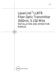
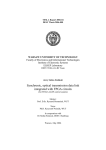
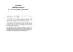
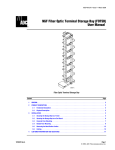
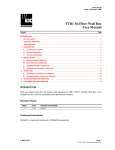
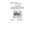
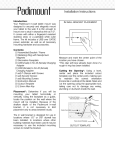
Thermal Adhesive Coated (TAC) Fiber Installation Instructions TECP-90-465 Issue 2 9/2014 Content Page INTRODUCTION . . . . . . . . . . . . . . . . . . . . . . . . . . . . . . . . . . . . . . . . . . . . . . . . . . . . . . . . . . . . . . . . . . . . . . . . . . . . . 1 1 PRODUCT DESCRIPTION . . . . . . . . . . . . . . . . . . . . . . . . . . . . . . . . . . . . . . . . . . . . . . . . . . . . . . . . . . . . . . . . . . 2 2 PLANNING . . . . . . . . . . . . . . . . . . . . . . . . . . . . . . . . . . . . . . . . . . . . . . . . . . . . . . . . . . . . . . . . . . . . . . . . . . . . 3 3 READYING THE TAC FIBER APPLICATOR TOOL . . . . . . . . . . . . . . . . . . . . . . . . . . . . . . . . . . . . . . . . . . . . . . . . . . . 5 4 INSTALLING TAC FIBER . . . . . . . . . . . . . . . . . . . . . . . . . . . . . . . . . . . . . . . . . . . . . . . . . . . . . . . . . . . . . . . . . . . 6 5 TOUCH UP ADHESIVE APPLICATION INSTRUCTIONS . . . . . . . . . . . . . . . . . . . . . . . . . . . . . . . . . . . . . . . . . . . . . . 10 6 REMOVAL INSTRUCTIONS . . . . . . . . . . . . . . . . . . . . . . . . . . . . . . . . . . . . . . . . . . . . . . . . . . . . . . . . . . . . . . . . 11 7 CUSTOMER INFORMATION AND ASSISTANCE . . . . . . . . . . . . . . . . . . . . . . . . . . . . . . . . . . . . . . . . . . . . . . . . . . . 12 2.1 Planning and Training Video . . . . . . . . . . . . . . . . . . . . . . . . . . . . . . . . . . . . . . . . . . . . . . . . . . . . . . . . . . 4 INTRODUCTION This document provides installation instructions for TE Thermal Adhesive Coated (TAC) Fiber. When TAC fiber is heated using the TE application tool, and according to the instructions detailed in this document, the fiber adheres to surfaces like wood molding that it is being installed on. The result is speed and ease of installation and reduced installation cost. 300100102451 Rev B Page 1 © 2014 Tyco Electronics Corporation. All Rights Reserved. TECP-90-465 • Issue 2 • 9/2014 Revision History ISSUE DATE 1 4/2014 Original. REASON FOR CHANGE 2 9/2014 Animation link corrected. Trademark Information TE (icon), TE Connectivity (logo), and TAC Fiber are trademarks of Tyco Electronics Corporation. Admonishments Important safety admonishments are used throughout this manual to warn of possible hazards to persons or equipment. An admonishment identifies a possible hazard and then explains what may happen if the hazard is not avoided. The admonishments — in the form of Dangers, Warnings, and Cautions — must be followed at all times. Danger: Danger is used to indicate the presence of a hazard that will cause severe personal injury, death, or substantial property damage if the hazard is not avoided. Warning: Warning is used to indicate the presence of a hazard that can cause severe personal injury, death, or substantial property damage if the hazard is not avoided. Caution: Caution is used to indicate the presence of a hazard that will or can cause minor personal injury or property damage if the hazard is not avoided. General Warning and Caution Statements Caution: The applicator tool used in the TAC Fiber System heats to about 230o F (110o C). Discomfort to the hand may be avoided by using the tool as described in this document. Caution: Only use the applicator tool with TAC fiber. It is not intended as a general purpose soldering iron. Caution: When not using the applicator tool, set it down on a flat surface not susceptible to heat. Never set the tool down near materials like curtains that may burn or on surfaces like carpets, rug fibers, counter tops, and plastics that may melt or discolor from heat. 1 PRODUCT DESCRIPTION Thermal Adhesive Coated (TAC) Fiber is optical fiber coated with an adhesive that when heated adheres to the surface on which the fiber is being installed. A hand-held applicator tool (separately ordered) is used to heat the adhesive and hold the fiber when installing it. TAC fiber has a 900 micron diameter (1.2 um with coating included). It is of Reduced Bend Radius (RBR) construction, and is available in lengths of 300, 500, or 1000 feet (91.4, 152.4, or 304.8 meters). Page 2 © 2014 Tyco Electronics Corportation. All Rights Reserved. TECP-90-465 • Issue 2 • 9/2014 TAC fiber is transparent; once installed, it is almost undetectable to the casual observer. Installation is quick without use of caulking, staples, or brackets. No tools are required other than the applicator tool provided. Radius limiters (sold separately) are installed at corners to protect the fiber from being bent too sharply. 2 PLANNING Before installing the TAC fiber, plan the physical route from origination point to termination. Refer to Figure 1 for what to do and to Figure 2 for what not to do in routing TAC fiber. Observe the following guidelines: 1. Use the shortest route compliant with these guidelines. 2. Whenever possible, route the fiber in a horizontal or vertical direction (except at obvious verticals such as a stairwell). 3. Whenever possible, route the fiber along corners of trim such as molding or a door frame. 4. If the point of origin for the fiber is in the middle of a wall, route the fiber in a vertical direction to the nearest horizontal extension such as the floor. 5. Minimize the number of bends; route the fiber in a straight line as far as physically possible and consistent with these guidelines. 6. Avoid runs of TAC fiber in knock-prone areas such as on exposed corners and doors without molding. MINIMIZE NUMBER OF BENDS ROUTE DIRECTLY FROM WALLBOX TO NEAREST HORIZONTAL EXTENSION FOLLOW ALONG TRIM WHEREVER POSSIBLE WHEREVER POSSIBLE ROUTE IN HORIZONTAL OR VERTICAL DIREC TION 25417-B Figure 1. Things to Do in Selecting a Fiber Route (Sample Route) Page 3 © 2014 Tyco Electronics Corporation. All Rights Reserved. TECP-90-465 • Issue 2 • 9/2014 7. Avoid runs of fiber through places such as the hearth of a fireplace where the fiber may be subjected to heat. 8. Avoid runs that will be visually noticeable due to location as indicated in Figure 2. Check over the route, noting all places where the fiber will bend around outside corners of molding or other structures. Install radius limiters in these places or route the fiber in an arc in visually non-noticeable places. DO NOT USE DIAGONAL RUNS EXCEPT ON DIAGONAL STRUCTURES LIKE STAIRWELL TRIM AVOID RUNS THAT WILL BE VISUALLY NOTICEABLE AVOID RUNS IN PLACES WHERE FIBER MAY BE SUBJECTED TO HEAT AVOID RUNS IN KNOCK-PRONE AREAS 25416-B Figure 2. Things Not to Do 2.1 Planning and Training Video If this user manual is a PDF and the computer has an internet connection, click on Figure 3 to view a planning and training video. Otherwise, use the following URL to access the video: http://bcove.me/59vsh64u Figure 3. Planning and Training Video Page 4 © 2014 Tyco Electronics Corportation. All Rights Reserved. TECP-90-465 • Issue 2 • 9/2014 3 READYING THE TAC FIBER APPLICATOR TOOL Note: Use only fresh or freshly charged batteries when readying the applicator tool for use in installing TAC fiber, The TAC fiber applicator tool (separately ordered) is used to heat and direct TAC fiber as it is installed. When power is applied to the tool, the tip becomes heated. During installation, the TAC fiber is drawn through the heating element to the surface on which the fiber is being installed. The sleeve holds the fiber on the tip. A steady rate of application ensures that the fiber is consistently heated. The recommended rate is one inch per second. Familiarize yourself with the terms shown in Figure 4 for the various parts of the applicator tool. These terms are used throughout this document. ON/OFF SWITCH COLLAR PROTECTIVE KNOB 25415-B TIP SLEEVE HANDLE MOUNTING SCREW Figure 4. Applicator Tool Exploded View ELECTRICITY PRESENT LED OPERATION LIGHT 25416-B Figure 5. Applicator Tool Assembled Use the follow procedure to ready the applicator tool: 1. Carefully unpack and inspect the applicator tool prior to use. Page 5 © 2014 Tyco Electronics Corporation. All Rights Reserved. TECP-90-465 • Issue 2 • 9/2014 2. Install four AA batteries per the diagram on the side of the tool. 3. Slide the on/off switch all the way forward and press the ON button. Refer to Figure 6. The red light should come on. If not, check to see if the batteries are installed properly. Figure 6. On/Off Switch and ON Button 4 INSTALLING TAC FIBER Adhesive coated TAC fiber achieves optimum results where two surfaces (planes) intersect, forming a 90o angle, inside corner, or protective path for the fiber. Use the following procedure to install the TAC fiber. 1. Select the optimum path for the TAC fiber as instructed in Topic 2 on Page 3. 2. With a clean damp cloth, wipe the pathway clear of dust and debris before applying the TAC fiber. For dirtier surfaces or greasy spots, use an isopropyl alcohol wipe to clean the surface. Let the cleaned surfaces dry before applying the TAC fiber. Note: Thorough surface preparation is essential or an optimum bond. The fiber will not adhere properly to dirty or greasy surfaces. 3. Install radius limiters wherever the fiber will be bent around or within a corner. Note: Sharp bends in the fiber may result in a loss of strength in the optical signal passing through the fiber. Radius limiters ensure bend radius is great enough to prevent signal loss. 4. Hold the TAC fiber on the tip, positioned within the narrow channel shown in Figure 7. Slide the sleeve over the fiber and tip. Continue inserting the TAC fiber until the fiber is more than an inch past the end of the tip. Page 6 © 2014 Tyco Electronics Corportation. All Rights Reserved. TECP-90-465 • Issue 2 • 9/2014 Figure 7. Sliding Sleeve over Tip With Fiber in Narrow Channel 5. Re-install the protective sleeve as shown in Figure 8. Figure 8. Tightening Protective Knob on Sleeve Note: To be heated properly, the TAC fiber must be positioned within the narrow channel on the bottom of the tip as shown in Figure 7. Page 7 © 2014 Tyco Electronics Corporation. All Rights Reserved. TECP-90-465 • Issue 2 • 9/2014 6. Slide the on/off switch all the way forward to its highest setting and if equipped lightly depress and hold down the ON button as shown in Figure 9. Note: On some models, the ON button must be depressed while operating the device. The red light should be on when the device is in use. Make sure the installation tip is hot before installing the TAC fiber. In ambient conditions of 65o F (68o C) and higher, the installation tip will reach its operating temperature of 230o F (110o C) in about a minute to a minute and a half. Caution: When not using the applicator tool, set it down on a flat surface not susceptible to heat. Never set the tool down near materials like curtains that may burn or on surfaces like carpets, rug fibers, counter tops, and plastics that may melt or discolor from heat. Figure 9. Applicator Tool Ready to Use 7. Begin installing the TAC fiber by moving the applicator tool along the installation route with light but constant pressure of one hand while guiding the fiber with the other hand, as shown in Figure 10. Note: The optimum speed for installing TAC fiber is one inch per second. Move the applicator tool forward steadily at the correct speed to ensure that the fiber is heated to the optimum temperature, providing the optimum adhesion. Note: Increase in fiber tension may indicate low battery power. To correct for low battery power, replace or recharge the batteries. Note: Increase in fiber tension may result from the lead fiber being bent at too great an angle from the direction of application, To correct for fiber angle, hold the fiber out straight as shown in Figure 10. Page 8 © 2014 Tyco Electronics Corportation. All Rights Reserved. TECP-90-465 • Issue 2 • 9/2014 Figure 10. Installing TAC Fiber (Note Use of Free Hand to Hold Lead Fiber Straight Out in Direction of Application) 8. Once three to four inches of TAC fiber has been attached to the surface, let go of the TAC fiber being held at the starting position. Adhere to the guidelines provided in Table 1 for straight aways, inside corners, and outside corners. Table 1. Installation Details SITUATION GUIDELINES Straight Away Once three to four inches of fiber have been attached to the surface, proceed at a steady pace (about one inch per second). Slow down if the fiber is not attaching. If this happens, move the device (with the power ON) back onto the area that did not attach and then continue forward. When encountering uneven surfaces, obstacles, or gaps between trim and the wall along the installation path, the installation tip allows the operator to favor one side or the other of the installation path and can switch back and forth as needed. Large obstacles such as conduits can be easily traversed by slowing down, maintaining contact with the surface, and directing the TAC fiber’s path with the installation tip. Do not press the fiber into gaps such as one between the wall and trim board as this may pinch the fiber Inside Corner Slow down when approaching an inside corner. Come to a stop where the corner arch begins; pause several seconds. Slowly start the arch through the corner, maintaining a 5.0 mm radius or greater and continue with installation. If needed, the fiber can be held against the wall with your index finger for several seconds to secure its position through the corner Outside Corner Slow down when approaching an outside corner. Come to a stop prior to making the turn around the outside corner; pause for several seconds. Slowly start around the corner, maintaining a 5.0 mm radius or greater and continue with installation. If needed, the TAC fiber can be held against the wall with your index finger for several seconds to secure its position through the corner Page 9 © 2014 Tyco Electronics Corporation. All Rights Reserved. TECP-90-465 • Issue 2 • 9/2014 Note: The installation tip rides on top of the TAC fiber preventing damage to the surface. Do not press too hard as this may damage the installation surface or the tip. 9. When attaching the TAC fiber to only one surface or to uneven surfaces, follow the instructions above and then, if necessary, apply TAC Fiber Touch Up Adhesive over the installed TAC fiber. Apply the touch up adhesive over the TAC fiber as needed depending on the length of the run and surface conditions. Note: Wait one hour after completing the installation before painting the surfaces where TAC fiber is installed. 5 TOUCH UP ADHESIVE APPLICATION INSTRUCTIONS TE Touch Up Adhesive should be applied to areas where the TAC fiber is exposed to only a single plane surface or installed along a non-continuous or porous surface such as brick, stucco, and textured walls. TE Touch Up Adhesive is a quality general adhesive designed for interior spaces. It bonds with most common building materials, is paintable, and allows for easy clean water clean-up. The adhesive goes on white and dries to a clear state. The touch up adhesive has the following properties: • Working time: < 15 minutes at 77° F (25° C) and 50% RH • Tack free time: < 60 minutes at 77° F (25° C) and 50% RH • Full cure ¼ inch bead per 24 hours • Paintable: Yes • Service temperature: 0° F to 160° F (-17° to 71° C) • Application temperature: 40° F to 120° F (4° to 49° C) • Odor: None • Vehicle Acrylic Latex Polymer • Flash point: None • Shelf life: 12 Months Use the following procedure to apply the touch up adhesive: 1. Prepare for application. For best results: • Surface must be dry and free of dirt, dust, oil, greases, mildew, and loose paint. • Apply in temperatures from 40° F to 120° F (4° to 49° C). • Store away from extreme heat and cold. 2. Place applicator tip on tube. 3. Gently squeeze tube to apply approximately a 1/8-inch bead of calk directly in top of TAC fiber. Smooth out bead as required. Page 10 © 2014 Tyco Electronics Corportation. All Rights Reserved. TECP-90-465 • Issue 2 • 9/2014 4. Clean up excess material with a damp sponge or cloth before it skins over. Wash hands with warm water and soap. 6 REMOVAL INSTRUCTIONS If it becomes necessary to remove TAC fiber after it has been installed, use the following procedure. Refer to Figure 11. 1. Carefully remove the sleeve and protective knob from the tip of the applicator tool. 2. Warm the tip up for about a minute and a half to allow the tip to reach operating temperature. 3. Carefully slide the tip over the attached fiber and slide it along the path while gently pulling the fiber off of the surface at a 90o or greater angle, pulling along the attached TAC fiber’s path. 4. To remove adhesive residue, use the heated tip to soften and scrape the adhesive residue off the surface, being careful not to gouge the surface with the tip’s sharp edges. 5. Repeat as needed. 6. To remove any residual adhesive residue, use cloths moistened with a general purpose adhesive remover. Figure 11. Applying Heated Tip to Fiber to Remove It Page 11 © 2014 Tyco Electronics Corporation. All Rights Reserved. TECP-90-465 • Issue 2 • 9/2014 7. Continue cleaning until all adhesive residue area has been removed. 8. Let the surface dry before re-installing additional TAC fiber. 7 CUSTOMER INFORMATION AND ASSISTANCE For technical support on this product; call 1.800.366.3891, extension 73475 (direct 1.952.917.3475) or email using [email protected]. TE website address is www.te.com. Page 12 © 2014 Tyco Electronics Corportation. All Rights Reserved.