1
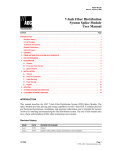
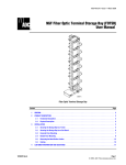
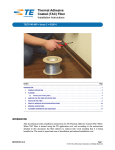
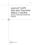
ADCP-90-250 Issue 1, November 1996 FTD1 36-Fiber Wall Box User Manual Content Page INTRODUCTION ........................................................................... 1 Revision History ....................................................................... 1 Trademark Information .................................................................. 1 Admonishments ....................................................................... 2 1. DESCRIPTION......................................................................... 2 A. Functional Description ............................................................... 2 B. Physical Description ................................................................ 2 C. Technical Description ............................................................... 5 2. INSTALLATION ........................................................................ 6 A. Wall Mounting the Wall Box ........................................................... 6 B. Rack Mounting the Wall Box .......................................................... 7 C. Installing Wall Box Components ....................................................... 7 D. Replacement Procedure — Key Locks.................................................. 11 3. OPERATION ......................................................................... 12 A. Cleaning the Connectors and Adapters ................................................. 13 B. Routing the Patch Cords in the Wall Box ................................................ 13 4. SYSTEM INTEGRATION SERVICES ....................................................... 14 5. CUSTOMER SUPPORT SERVICES ........................................................ 14 INTRODUCTION This user manual describes the features and functions of ADC’s FTD1 36-Fiber Wall Box. Also included are the wall box installation and operation procedures. Revision History ISSUE DATE REASON FOR CHANGE 1 11/96 Original Trademark Information Hubbell is a registered trademark of Hubbell Incorporated 4-40001-2326 Page 1 1996, ADC Telecommunications, Inc. ADCP-90-250 Issue 1, November 1996 Admonishments Important safety admonishments are used throughout this manual to warn of possible hazards to persons or equipment. An admonishment identifies a possible hazard and then explains what may happen if the hazard is not avoided. The admonishments — in the form of Dangers, Warnings, and Cautions — must be followed at all times. These warnings are flagged by use of the triangular alert icon (seen below), and are listed in descending order of severity of injury or damage and likelihood of occurrence. Danger: Danger is used to indicate the presence of a hazard that will cause severe personal injury, death, or substantial property damage if the hazard is not avoided. Warning: Warning is used to indicate the presence of a hazard that can cause severe personal injury, death, or substantial property damage if the hazard is not avoided. Caution: Caution is used to indicate the presence of a hazard that will or can cause minor personal injury or property damage if the hazard is not avoided. 1. DESCRIPTION This section provides functional, physical, and technical descriptions of the wall box. 1.01 See Figure 1. 8513-A Figure 1. FTD1 36-Fiber Wall Box Page 2 1996, ADC Telecommunications, Inc. ADCP-90-250 Issue 1, November 1996 A. Functional Description The FTD1 36-Fiber Wall Box (Figure 1) is designed to provide a wall-mounted, or rack1.02 mounted, secure, fiber cable terminal for use in small to medium-sized fiber networks and customer premises applications. The wall box can accommodate up to four OSP cables and contains provisions for splicing and terminating 36 singlemode fiber circuits. The area behind the left front cover of the wall box houses three four-meter, 12-fiber, 1.03 soft wall bundle fiber cables. The connectorized ends of these cables are terminated to fiber optic adapters in angled retainers on the bulkhead between the two sections of the wall box. The service loops of these cables are stored on four radius limiters, and the stub ends of the cable fibers are spliced to Outside Plant (OSP) cable fibers in heat shrink fusion splice chips in three splice trays. Up to four OSP cables can enter from either above or below the wall box (i.e., two from above and two from below). A Hubbell connector kit and four cable clamps are supplied with the wall box — enough to secure one OSP cable to the wall box and provide strain relief for four OSP cables. A rubber grommet is provided (unattached) for use as a dust cover at whichever corner (top or bottom) is not used for cable entrance. The area behind the right front cover of the wall box is used for terminating 3mm 1.04 singlemode patch cords to the adapters. The patch cords can enter from either above or below the wall box. A rubber grommet is used as a dust cover at the panel opening that is not used for patch cord entry. B. Physical Description The wall box is 19 inches (48.26 cm) wide, 10 inches (25.4 cm) high, and 4.76 inches 1.05 (12.1 cm) deep, and is constructed of heavy gauge aluminum, painted putty white. Both hinged front covers are equipped with pull handles and key locks. Some of the physical features of the wall box are pointed out in Figure 2. Page 3 1996, ADC Telecommunications, Inc. ADCP-90-250 Issue 1, November 1996 ACCESS COVER TO CABLE SERVICE LOOPS, SPLICES, ETC. 8515-A KEY LOCKS CONNECTOR ACCESS COVERS Figure 2. Wall Box Features Chassis The wall box has four mounting holes at the corners of a rectangle that is 8.5 inches 1.06 (21.6 cm) high and 14 inches (35.6 cm) wide (see Figure 3). The rear panel has two slots for the splice strap assembly that retains the splice trays. The left side of the wall box includes provisions for mounting a Hubbell connector kit (supplied) and four (staggered, high and low) cable clamp kits; also included are provisions (kits) for grounding the OSP cables to the wall box. 14.00 IN. (35.6 CM) 4.25 IN. (10.8 CM) 8.5 IN. (21.6 CM) 8516-B Figure 3. Mounting Hole Pattern Page 4 1996, ADC Telecommunications, Inc. ADCP-90-250 Issue 1, November 1996 The splice trays are positioned on the back panel of the left side of the wall box (see 1.07 Figure 4). They are secured by a horizontal splice strap assembly, the right end of which unhooks from the chassis. There is one radius limiter at each corner of this area. LOWER CABLE CLAMP KIT SPLICE TRAYS UPPER CABLE CLAMP KIT GROUNDING STUD ASSEMBLIES HUBBELL CONNECTOR KIT FC ADAPTERS/ RETAINERS 8517-B Figure 4. Wall Box Details C. Technical Description 1.08 Table 1 lists typical specifications for a wall box that is fully cabled by the manufacturer. Table 1. Wall Box Specifications (Typical) PARAMETER SPECIFICATION Adapters/Retainers 36 Cables 3 Splice Trays 3 Dimensions: Height 10 inches (25.4 cm) Width 19 inches (48.26 cm) Depth 4.76 inches (12.1 cm) Weight (approximate) 30 pounds (13.61 kg) Page 5 1996, ADC Telecommunications, Inc. ADCP-90-250 Issue 1, November 1996 2. INSTALLATION Warning: Never install telephone equipment in a wet location or during a lightning storm. When installing or modifying telephone lines, disconnect lines at the network interface before working with uninsulated lines or terminals to prevent electrical shock. A. Wall Mounting the Wall Box It is recommended that the wall box be installed on a 3/4-inch thick plywood panel 2.01 attached to the wall, in accordance with local fire code. If the wall surface is uneven, shim the plywood as required to ensure a flat mounting surface. The plywood panel and the surface to which it is attached must provide adequate support for the wall box and any other attached equipment. When mounting the wall box directly to concrete, steel, or other surface, select fasteners capable of supporting the weight and withstanding normal cabling and splicing activity. Note: Before mounting the wall box, unlock and open the left front cover, then install (from the back) any needed ground stud assemblies near the left side of the wall box. See Figure 5. Sufficient hardware for four stud assemblies is supplied with the wall box. STUD NUTS WASHERS 8518-A BACK OF MODULE Figure 5. Ground Stud Assembly Installation Four wall mounting slots (shown in Figure 3) are provided in the rear panel of the wall 2.02 box. Use these four mounting holes to attach the wall box to the mounting surface. Install the wall box as follows: 1. Unlock and open both front covers of the wall box, then position the wall box on the mounting surface and check that it is level. When mounting the wall box on plywood, skip steps 2 and 3 and go to step 4. 2. When mounting the wall box on a surface other than wood, mark the locations of the four mounting holes with a pencil or felt-tip pen. Using the fastener manufacturer’s instructions, install the wall fasteners at the four marks. 3. Position the wall box over the four fasteners, then secure it in position using the appropriate hardware. 4. When mounting the panel on plywood, use a sharp awl, small drill, or nail to make pilot holes for the four half-inch #6 wood screws supplied. 5. Mount the wall box on the plywood panel using the four #6 wood screws. Page 6 1996, ADC Telecommunications, Inc. ADCP-90-250 Issue 1, November 1996 B. Rack Mounting the Wall Box The FTD1 36-Fiber Wall Box can be rack-mounted in a 19-inch frame. This is 2.03 accomplished by inserting a #12 screw through the 1/4-inch slots in each corner of the rear panel of the wall box, into the threaded mounting holes in the frame. The upper two vertical mounting slots are approximately one-half inch long; those in the bottom corners are one inch long. C. Installing Wall Box Components Additional components available for use in the wall box include Hubbell connector kits, 2.04 lower cable clamp kits, upper cable clamp kits; grounding kits; three splice trays, and a sheet of fiber designation labels. Clamping OSP Cables OSP cables can be clamped to the wall box using a Hubbell connector kit and cable 2.05 clamp assembly. Hubbell Connector Kit The Hubbell connector kit (Figure 6) is installed on-site to secure an OSP cable to the 2.06 bottom (or top) of the wall box. Each Hubbell connector kit includes all the parts necessary to secure an OSP fiber cable to the wall box. 1. Using the cinch nut on the inside, mount the Hubbell connector in the upper or lower left corner of the wall box. 2. Remove the compression nut, split ring and bushing from the body of the Hubbell connector, then place them (in that order) over the end of the OSP cable onto the cable jacket. 3. Route the OSP cable through the Hubbell connector into the wall box, then strip the outer sheath of the end of the cable to expose the inner fibers or subunits. 4. After adjusting and clamping the OSP cable with a cable clamp kit (below), slide the compression nut, split ring and bushing up (or down) the cable and thread the compression nut onto the connector body and tighten it securely. Page 7 1996, ADC Telecommunications, Inc. ADCP-90-250 Issue 1, November 1996 CLINCH NUT CONNECTOR BODY BUSHING SPLIT RING COMPRESSION NUT 0SP CABLE HUBBELL CONNECTOR (ASSEMBLED) 8993-A Figure 6. Hubbell Connector Kit Cable Clamp Kits The cable clamp kits (Figures 7 and 8) are installed on-site to separate the incoming OSP 2.07 cable fibers for easier management within the wall box. Each cable clamp kit includes a mounting plate (upper or lower; i.e., high or low), a clamp cover plate, two rubber yokes, a set of five rubber grommets, and associated hardware (two mounting screws and two clamp screws). Note: The breakout lengths of the OSP cable fibers should be long enough to extend 2.5 times around the radius limiters that surround the splice tray. 1. Mount the selected cable clamp mounting plate (either high or low) using two #4 mounting screws into the rear panel of the wall box per Figure 7 or Figure 8. 2. Select a grommet which (when placed around the cable), has a gap within the range of nearly zero to 0.30 inch (0 to 8 mm). If the outer diameter of the cable is 0.7 to 0.8 inch (1.78 to 2.03 cm), no grommet is required. 3. Assemble the cable clamp components as shown in Figure 7 or 8: secure the cable and grommet (if used) between the two cable clamp yokes, then place the clamp plate over the outer yoke and secure the yokes and cable to the mounting plate with two long screws. Be sure the cable sheath extends approximately 0.75 inch (1.9 cm) beyond the cable clamp. 4. Repeat steps 1 through 3 as necessary to install additional cable clamp kits. Page 8 1996, ADC Telecommunications, Inc. ADCP-90-250 Issue 1, November 1996 RUBBER GROMMET CABLE CLAMP MOUNTING PLATE CABLE CLAMP YOKES CLAMP SCREWS #4 MOUNTING SCREWS 8519-A CABLE CLAMP TOP PLATE Figure 7. Lower Cable Clamp Assembly Details RUBBER GROMMET #4 MOUNTING SCREWS CABLE CLAMP YOKES CLAMP SCREWS CABLE CLAMP MOUNTING PLATE 8520-A CABLE CLAMP TOP PLATE Figure 8. Upper Cable Clamp Assembly Details Splicing OSP Cable(s) to Fiber Cables If the soft wall bundle fiber cables are already installed and routed to the splice trays, 2.08 prepare the ends of the OSP cable(s) and splice them to the fiber cables according to local practice for heat shrink fusion splices. For your convenience, Figure 9 provides a cross reference between the retainer/adapter positions and the color-coded fibers in the fiber cables. The adapter numbers are also marked approximately two inches (five cm) from the end of the cable jacket at the stub ends of the fibers. Page 9 1996, ADC Telecommunications, Inc. ADCP-90-250 Issue 1, November 1996 Routing Cables in Splice Trays (Two Methods) Figures 10 and 11 show recommended methods for routing fiber cables and pigtails in 2.09 the two types of splice trays that are available for use in this wall box. Mounting Splice Trays After all the splices in a given splice tray are completed, mount the splice tray on the 2.10 back panel of the wall box using the splice strap assembly (supplied). Stack the three splice trays and secure them with the splice strap assembly. 1 2 3 4 5 6 7 8 9 10 11 12 13 14 15 CABLE FIBERS* 16 17 18 19 20 21 22 23 24 25 26 27 28 29 30 31 32 33 34 35 36 POSITION 1, 13, 25 2, 14, 26 3, 15, 27 4, 16, 28 5, 17, 29 6, 18, 30 7, 19, 31 8, 20, 32 9, 21, 33 10, 22, 34 11, 23, 35 12, 24, 36 COLOR BLUE ORANGE GREEN BROWN SLATE WHITE RED BLACK YELLOW VIOLET ROSE AQUA PATCH CORD (RIGHT) SIDE VIEW * AS FULLY CABLED FROM THE MANUFACTURER. 8521-B Figure 9. Connector Position/Fiber Color-Code Cross Reference Page 10 1996, ADC Telecommunications, Inc. ADCP-90-250 Issue 1, November 1996 Installing Fiber Cables If you purchased a “bare” wall box and now need to install the fiber cables, install the 2.11 angled retainers and adapters one at a time in the vertical bulkhead plate in the front section of the wall box. The right side of each adapter should be pointing downward. Terminate the connectors to the left side of the adapters, then route the fiber cable(s) clockwise around the four radius limiters in the left side of the wall box as shown in Figure 4. Route the stub ends of the cables into one of the splice trays. Grounding Kit Each grounding kit for the wall box consists of a 12-inch length of AWG #6 stranded 2.12 wire with a #6 ring terminal, together with a #6 - 14 lug connector and a shield connector. The grounding kits are to be used for grounding OSP cables to the ground stud assemblies previously installed on the rear panel of the wall box. If an OSP cable has a grounding tab, connect it to the nearest ground stud (Figure 5) using the grounding kit. Fiber Designation Labels Two sheets of labels are provided with the wall box. Use the Brady labels to mark the 2.13 stub ends of individual OSP cable fibers. The strip labels on the other sheet can be put on the inside of the left front cover of the wall box (as shown in Figure 10) to identify the destinations of the 36 patch cords. D. Replacement Procedure — Key Locks Each front cover of the wall box has a key lock for security. Use the following procedure 2.14 to replace the key locks: 1. From inside the front cover, remove the lock nut that holds the key lock to the cover (see Figure 1). 2. Remove the key lock from the front of the cover. Note: Install the replacement key lock so the “teeth” of the key will be down in the locked position; furthermore, the lock on the right should open when turned clockwise, and the lock on the left should open when turned counterclockwise. 3. While the key lock is in the “locked” position (i.e., pointing straight up), insert the key lock through the cutout; then install and tighten the lock nut while keeping the locking tab pointing straight up (i.e., in the 12 o’clock position). 4. Operate the key lock several times to ensure that it operates correctly (i.e., that the left key lock opens when the key is turned counterclockwise and the right key lock opens when the key is turned clockwise). Page 11 1996, ADC Telecommunications, Inc. ADCP-90-250 Issue 1, November 1996 CAUTION LASER RADIATION DO NOT LOOK INTO CONNECTOR 1 2 3 CAUTION LASER RADIATION DO NOT LOOK INTO CONNECTOR 4 5 6 CAUTION LASER RADIATION DO NOT LOOK INTO CONNECTOR 7 8 9 CAUTION LASER RADIATION DO NOT LOOK INTO CONNECTOR 10 11 12 CAUTION LASER RADIATION DO NOT LOOK INTO CONNECTOR 13 14 15 CAUTION LASER RADIATION DO NOT LOOK INTO CONNECTOR 16 17 18 CAUTION LASER RADIATION DO NOT LOOK INTO CONNECTOR 19 20 21 CAUTION LASER RADIATION DO NOT LOOK INTO CONNECTOR 22 23 24 CAUTION LASER RADIATION DO NOT LOOK INTO CONNECTOR 25 26 27 CAUTION LASER RADIATION DO NOT LOOK INTO CONNECTOR 28 29 30 CAUTION LASER RADIATION DO NOT LOOK INTO CONNECTOR 31 32 33 CAUTION LASER RADIATION DO NOT LOOK INTO CONNECTOR 34 35 36 8522-A Figure 10. Patch Cord Destination Labels 3. OPERATION Operation consists of routing 3mm fiber patch cords into the wall box, cleaning the 3.01 mating connectors and adapters, then mating the patch cord connectors to the adapters on angled retainers in the wall box, storing the service loop on two radius limiters in the right side of the wall box, and removing the slack from the patch cord service loops. Page 12 1996, ADC Telecommunications, Inc. ADCP-90-250 Issue 1, November 1996 A. Cleaning the Connectors and Adapters Dust and other contaminants on fiber optic connectors and adapters can seriously 3.02 degrade circuit performance. To prevent contamination, unused connectors and adapters must be protected with clean dust caps. Routine termination activity can also introduce contaminants; therefore, it is essential that connectors and adapters be cleaned just before making connections. The cleaning kit available from ADC (catalog number FPC-CLNKIT) can be used to 3.03 clean the connectors and adapters used in the wall box. B. Routing the Patch Cords in the Wall Box After terminating a patch cord connector to an adapter in the wall box, route the patch 3.04 cord either straight out the bottom of the wall box, or route it in a counterclockwise direction around the two radius limiters and then out the top or bottom of the wall box. Carefully remove most of the slack from the service loops as in Figure 11. RADIUS LIMITERS 8523-A Figure 11. Patch Cord Routing in the Wall Box Page 13 1996, ADC Telecommunications, Inc. ADCP-90-250 Issue 1, November 1996 4. SYSTEM INTEGRATION SERVICES ADC offers the following system integration services. For calls originating in the U.S.A. 401 or Canada, dial 1-800-366-3891, extension 3000. For calls originating outside the U.S.A. or Canada, dial 612-946-3000. Technical Assistance Center • • • • • • • • • • • Product Management Project Engineering Project Administration Network Design Broadband Design (RF Design and Strand Mapping) Integration Network Testing Network Monitoring (Upstream or Downstream) Power Monitoring Remote Surveillance System Turn-Up and Test Service/Maintenance Agreements Technical Training • Product Technology • Custom Designed Training Technical Operations • Detail Engineering • End-to-End Installation • Drafting Services 5. CUSTOMER SUPPORT SERVICES ADC offers the following customer support services. For calls originating in the U.S.A. 5.01 or Canada, dial 1-800-366-3891, then request the extension listed. For calls originating outside the U.S.A. or Canada, dial 612-946-3475 or 612-946-3000. BCG Technical Assistance Center Extension 3475 E-Mail: [email protected] • • • • • • • • Technical Information System/Network Configuration Product Specification Product Application Training Installation and Operation Assistance Troubleshooting and Repair Field Assistance Sales Administration Extension 3000 • • • • Quotation Proposals Ordering Delivery General Product Information Product Return Department Extension 3000 E-Mail: repair&[email protected] • ADC Return Authorization number and instructions must be obtained before returning products. Product information and service can also be obtained by writing ADC Telecommuni5.02 cations, Inc., 4900 West 78th Street, Minneapolis, Minnesota 55435, U.S.A. Page 14 1996, ADC Telecommunications, Inc. ADCP-90-250 Issue 1, November 1996 Contents herein are current as of the date of publication. ADC reserves the right to change the contents without prior notice. In no event shall ADC be liable for any damages resulting from loss of data, loss of use, or loss of profits and ADC further disclaims any and all liability for indirect, incidental, special, consequential or other similar damages. This disclaimer of liability applies to all products, publications and services during and after the warranty period. This publication may be verified at any time by contacting ADC’s Technical Assistance Center at 1-800-366-3891, extension 3475 (in U.S.A. or Canada) or 612-946-3475 (outside U.S.A. and Canada), or by writing to ADC Telecommunications, Inc., Attn: Technical Assistance Center, Mail Station #77, 4900 West 78th Street, Minneapolis, MN 55435, U.S.A. © 1996, ADC Telecommunications, Inc. All Rights Reserved Printed in U.S.A. Page 15