1
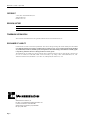
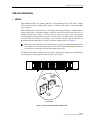
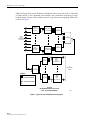
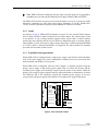
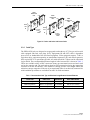
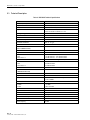
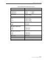
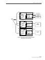
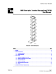
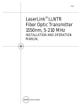
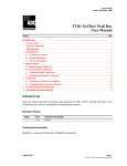
ADCP-61-814 Issue 1 April 1999 PWR-AVIS User Manual CLAS S2 SPAR SPARE –48V E RET (1) –48V(1) RET (2) (2) PS1 ALM A PS1 ALM B PS2 ALM A PS2 ALM B TEST 16 15 14 SIGN 13 12 AL O UTP 11 UT 10 9 8 7 6 AVIS -16 5 4 3 2 SIGN 1 AL IN PUT CHA SSIS GRO UND 12249-B 1052205 Rev A ADCP-61-814 • Issue 1 • April 1999 COPYRIGHT 1999, ADC Telecommunications, Inc. All Rights Reserved Printed in the U.S.A. REVISION HISTORY ISSUE DATE REASON FOR CHANGE 1 04/99 Original. TRADEMARK INFORMATION ADC and ADC Telecommunications are registered trademarks of ADC Telecommunications, Inc. DISCLAIMER OF LIABILITY Contents herein are current as of the date of publication. ADC reserves the right to change the contents without prior notice. In no event shall ADC be liable for any damages resulting from loss of data, loss of use, or loss of profits and ADC further disclaims any and all liability for indirect, incidental, special, consequential or other similar damages. This disclaimer of liability applies to all products, publications and services during and after the warranty period. This publication may be verified at any time by contacting ADC’s Technical Assistance Center at 1-800-366-3891, extension 3475 (in U.S.A. or Canada) or 612-946-3000 (outside U.S.A. and Canada), or by writing to ADC Telecommunications, Inc., Attn: Technical Assistance Center, Mail Station #71, P.O. Box 1101, Minneapolis, MN 55440-1101, U.S.A. ADC Telecommunications, Inc. P.O. Box 1101, Minneapolis, Minnesota 55440-1101 In U.S.A. and Canada: 1-800-366-3891 Outside U.S.A. and Canada: (612) 938-8080 Fax: (612) 946-3292 Page ii ADCP-61-814 • Issue 1 • April 1999 TABLE OF CONTENTS Content Page ABOUT THIS MANUAL .......................................................................v ADMONISHMENTS..........................................................................v GENERAL SAFETY PRECAUTIONS................................................................v 1 GENERAL.......................................................................... 1 2 DESCRIPTION ....................................................................... 3 2.1 Physical Description ............................................................. 3 2.2 Functional Description ............................................................ 4 2.3 Technical .....................................................................10 3 4 5 INSTALLATION ......................................................................12 3.1 Chassis Installation .............................................................12 3.2 Cabling .....................................................................14 OPERATION ........................................................................16 4.1 Passive Jack Access Card .........................................................16 4.2 Active Jack Access Card With Unity Gain ...............................................21 4.3 Amplifier Jack Access Card ........................................................27 CUSTOMER INFORMATION AND ASSISTANCE .................................................28 Page iii 1999, ADC Telecommunications, Inc. ADCP-61-814 • Issue 1 • April 1999 ABOUT THIS MANUAL This manual describes the ADC PWR-AVIS system. The manual provides a product description, installation instructions and operational information. ADMONISHMENTS Important safety admonishments are used throughout this manual to warn of possible hazards to persons or equipment. An admonishment identifies a possible hazard and then explains what may happen if the hazard is not avoided. The admonishments — in the form of Dangers, Warnings, and Cautions — must be followed at all times. These warnings are flagged by use of the triangular alert icon (seen below), and are listed in descending order of severity of injury or damage and likelihood of occurrence. Danger: Danger is used to indicate the presence of a hazard that will cause severe personal injury, death, or substantial property damage if the hazard is not avoided. Warning: Warning is used to indicate the presence of a hazard that can cause severe personal injury, death, or substantial property damage if the hazard is not avoided. Caution: Caution is used to indicate the presence of a hazard that will or can cause minor personal injury or property damage if the hazard is not avoided. GENERAL SAFETY PRECAUTIONS Shown here is the general admonishment that applies throughout the procedures in this manual. Warning: Warning is used to indicate the presence of a hazard that can cause severe personal injury, death, or substantial property damage if the hazard is not avoided. Page v 1999, ADC Telecommunications, Inc. ADCP-61-814 • Issue 1 • April 1999 PWR-AVIS USER MANUAL 1 GENERAL This manual describes the features, functions, and installation of the ADC Power Analog Video Interface System (PWR-AVIS) which is available with single or dual (redundant) power supplies. PWR-AVIS provides centralized access for testing, monitoring, patching, or amplification of digital, analog video, or baseband signals. Circuits are accessed via little coaxial jacks (LCJ) mounted on jack access cards. A variety of active and passive jack access cards provide various amplification and monitoring levels. The jack access card mates with a rear interface unit (RIU) that is mounted in the chassis. A rear interface unit provides the interface for permanent coaxial connections (F or BNC) to network elements (NE) (see Figure 1). Note Jack access cards are used in the RIU only for testing or troubleshooting functions. The number of access cards required in an office must be determined and ordered by the user based on expected provisioning and maintenance activity. The PWR-AVIS chassis contains one or two power supplies (depending upon configuration) and wiring for powering amplifier and active jack access cards. 1 2 3 4 5 6 7 8 9 10 11 12 13 14 15 16 TEST PWR 1 2 M M O I O I 6965-B REAR INTERFACE UNIT FROM VIDEO TRANSPORT SYSTEM TO VIDEO MODULATOR M O I JACK ACCESS CARD FRONT VIEW Figure 1. Jack Access Card and Rear Interface Unit Page 1 © 1999, ADC Telecommunications, Inc. ADCP-61-814 • Issue 1 • April 1999 PWR-AVIS is typically used in headend or distribution offices to provide access to individual 4.5 MHz (NTSC or PAL) baseband video channels, data, intermediate frequencies or other headend signals from the video backbone network. A typical network employing PWR-AVIS is shown in Figure 2. #1 VIDEO TRANSPORT SYSTEM MODULATOR/ UP CONVERTER 1 X 16 COMBINER #16 #1 #2 #1 #1 #1 #3 #4 FROM VIDEO BACKBONE NETWORK #5 1X8 COMBINER #6 #7 #8 #8 #8 #128 #113 VIDEO TRANSPORT SYSTEM MODULATOR/ UP CONVERTER 1 X 16 COMBINER #128 #1 VIDEO FIBER OPTIC TRANSMITTER 1X8 SPLITTER #1 #1 TO SUBSCRIBER NODES 1X8 SPLITTER #8 #64 LEGEND = AVIS TEST POINTS VIDEO FIBER OPTIC TRANSMITTER 1X8 SPLITTER #64 = VJ2000 TEST POINTS TYPICAL HEADEND/DISTRIBUTION OFFICE TEST JACK ARRANGEMENT Figure 2. Typical Access Jack/Equipment Arrangement Page 2 © 1999, ADC Telecommunications, Inc. 6405-A ADCP-61-814 • Issue 1 • April 1999 2 DESCRIPTION 2.1 Physical Description 2.1.1 Chassis The PWR-AVIS chassis are 3.5 inches (8.9 cm) high and mount in either 19- or 23-inch (48.3 or 58.4 cm) equipment racks. Reversible mounting brackets are provided for accommodating either rack type. The protective front cover slides into the chassis when circuit access is required. Hinged plates on the chassis mounting brackets provide an area for recording circuit identification. The PWR-AVIS chassis contains 17 RIUs (one for test) in which LCJ jack access cards or amplifier cards are installed. Two slots are located at the front of the chassis for installing one or two (depending upon configuration) power supply module(s). Office power connections for the power supply module(s) are made, as required, via two sets of -48V and RET terminals at the rear of the chassis. An AC to -48VDC power adapter (PWR-AVIS-110-ST) may be used when a -48VDC power source is not available. A cable management tray at the rear of the chassis supports the IN and OUT cables from the Network Elements. CA PA PA 48 1 1 48 P1 A 16 1 14 IA P 1 1 A 11 1 P1 A PA 9 8 PAA 6 AI-1 6 4 1 IA IP CAI D 12249-B Figure 3. PWR-AVIS Chassis 2.1.2 Power Supply Module The power supply modules slide into slots labeled PWR 1 and PWR 2 at the front of the chassis (see Figure 4). This DC to DC converter provides the necessary +5V power for the chassis. A green LED at the front of the power supply module, when lit, indicates that the power supply module is functioning properly. Page 3 © 1999, ADC Telecommunications, Inc. ADCP-61-814 • Issue 1 • April 1999 Note: If using the single power supply option, the module should only be inserted into the PWR 1 slot. Figure 4. Power Supply Module 2.2 Functional Description PWR-AVIS provides a central jack access point between network elements (NE). See Figure 5 on the next page. The jack access cards provide access to circuits for monitoring and maintenance functions. (The jack circuitry automatically provides 75-ohm termination.) The jacks also provide patching functions to bypass defective equipment and/or isolate problems in circuit links. The monitor jack is non-switching. Patching into this jack does not break the circuit and allows non-intrusive access. The unity gain (baseband video) card provides a 0 dB level at the monitor jack. The IN and OUT jacks incorporate a “make before break” switching design and self-terminate into 75-ohms to ensure high service performance without interruption. The IN switching jack provides access to the input signal of an NE. Patching into the jack opens the circuit and signals can be inserted for testing or patching to bypass defective equipment. The OUT switching jack provides access to the output signal of an NE. Patching into the jacks opens the circuit and signals can then be extended for testing or bypass functions. When patching arrangements do not extend the NE output signal, it is recommended that an external 75-ohm termination plug be inserted into the OUT switching jack. This provides greater signal isolation and reduces cross-talk level. The amplifier cards, which do not have jacks for circuit access, provide fixed gain amplification of an incoming signal by 0, 10 or 20 dB respectively for return path applications. Page 4 © 1999, ADC Telecommunications, Inc. ADCP-61-814 • Issue 1 • April 1999 FRONT JACKS MON REAR EQUIPMENT CONNECTIONS 75 OHM 75 OHM 500 OHM OUT OUT 0.056 µH INDUCTOR NETWORK ELEMENTS VIDEO TRANSPORT SYSTEM 0.033 µH INDUCTOR IN MODULATOR/ UP CONVERTER IN 75 OHM REAR INTERFACE UNIT JACK ACCESS CARD 10220-A 0 dB Unity Gain Amplifier Monitor Network FRONT JACKS REAR EQUIPMENT CONNECTIONS MON 75 OHM 464 OHM 93 OHM OUT VIDEO TRANSPORT SYSTEM OUT 0.056 µH INDUCTOR NETWORK ELEMENTS 0.033 µH INDUCTOR IN MODULATOR/ UP CONVERTER IN 75 OHM JACK ACCESS CARD REAR INTERFACE UNIT 6412-A 20 dB Below Active Signal Monitor Network REAR EQUIPMENT CONNECTIONS OUT 0, 10 or 20 dB AMPLIFIER 75 OHM NETWORK ELEMENTS SPLITTER 0.033 µH INDUCTOR MODEM IN JACK ACCESS CARD REAR INTERFACE UNIT 10229-A 0, +10 and +20 dB Gain Amp Cards Figure 5. Access Jack, Amp Cards and RIU Schematic Page 5 © 1999, ADC Telecommunications, Inc. ADCP-61-814 • Issue 1 • April 1999 2.2.1 2.2.1.1 Powering Options Single (Non-Redundant) Powering The single or non-redundant powering option provides one power supply module for powering the RIUs. Figure 6 shows an example of this configuration. Figure 6. PWR-AVIS With Single Power Supply Module 2.2.1.2 Dual (Redundant) Powering The dual or redundant powering option provides two power supply modules for powering the RIUs. Figure 7 shows an example of this configuration. Figure 7. PWR-AVIS With Dual (Redundant) Power Supply Modules Page 6 © 1999, ADC Telecommunications, Inc. ADCP-61-814 • Issue 1 • April 1999 Note: PWR-AVIS units configured with the single powering option can be upgraded to redundant power by ordering an additional power supply module (PWR-AVIS-PSC). The PWR-AVIS provides two sets of screw terminal contacts (see Figure 8) at the rear of the chassis for connecting to a -48V office power supply. Alternately, a 110-48V (PWR-AVIS110-ST) converter (purchased separately) can be attached to either set of contacts. 2.2.2 Alarms As shown in Figure 8, PWR-AVIS incorporates two pair of screw terminal alarm contacts (PS1-A and B, and PS2-A and B) located at the rear of the chassis. The contacts may be used as an interface to any existing customer-supplied alarm system. Both A and B contacts perform the same function and can be used with two independent types of warning signals, either audible or visual. If the power supply voltage drops below a normal operating threshold of 3.5VDC, failure is detected and alarm(s) are triggered. The alarm contacts are normally open and will close when a failure occurs. 2.2.3 Single/Dual Powering and Alarms When PWR-AVIS is configured with a single power supply, only the PS1 alarms should be used. If the power supply fails in this configuration continuity will occur between the PS1 alarm terminals and all RIUs will lose power. When PWR-AVIS is configured with two power supplies, it normally operates using the primary power supply. If the primary power supply fails, its alarms will activate and the secondary power supply will seamlessly begin to provide power to the chassis. When the primary power supply begins to operate properly (after replacement or maintenance), its alarm will deactivate and it will seamlessly override the secondary power supply. In all cases (except where both power supplies fail) all RIUs will continue to be supplied with power. CLASS 2 OUT IN SPARE SPARE –48V (1) RET (1) –48V (2) RET (2) TEST PS1 ALM A PS1 ALM B PS2 ALM A PS2 ALM B AVIS 12247-B Figure 8. Power and Alarm Contacts Page 7 © 1999, ADC Telecommunications, Inc. ADCP-61-814 • Issue 1 • April 1999 2.2.4 Rear Interface Units The RIU, mounted in the rear of the chassis, provides the interface for the coaxial cable and the jack access card which is plugged into the RIU from the front of the chassis. The interface connectors accept coaxial cable terminated with F or BNC connectors. See Figure 9. The RIU is factory wired with ± 5 V and ground for powering the jack access card when it is plugged into the RIU. The ± 5 V is passed to the jack access card through pins while the ground is connected through the RIU and card bodies. REAR INTERFACE UNIT JACK ACCESS CARD FROM VIDEO TRANSPORT SYSTEM TO VIDEO MODULATOR 6772-C Figure 9. RIU and Jack Access Card 2.2.5 AVIS Jack Access and Amplifier Cards There are three basic card circuit configurations available: • A passive (–20dB) card with Monitor, IN and OUT little coax jacks for full jack access. • An active (0 dB baseband video) card with Monitor, IN and OUT little coax jacks for full jack access. • Active (0, +10 and +20 dB gain amplifier) cards without access jacks. PWR-AVIS Cards, except for the 0,10 and 20 dB active (amplifier) cards, provide the means to access circuits for monitoring and maintenance functions or to amplify an incoming signal. See Figure 10. The monitor network circuitry for the active and passive cards provides access to the signal at 0 or -20 dB level respectively. The active card provides a 0 dB unity gain signal with respect to the output signal. The active amplifier cards provide fixed gain of 0, 10 and 20 dB respectively and are for return path application with bandwidth of 5 MHz to 200 MHz. Power (± 5 V) and ground for active cards is automatically transferred from the RIU when the card is plugged in. The cards with jack circuitry automatically provide 75-ohm circuit termination. Page 8 © 1999, ADC Telecommunications, Inc. ADCP-61-814 • Issue 1 • April 1999 REAR INTERFACE UNIT REAR INTERFACE UNIT REAR INTERFACE UNIT M MON O M OUT I O MON IN JACK ACCESS CARD OUT IN I BB 6409-B JACK ACCESS CARD BB AMPLIFIER CARD Figure 10. Passive and Active Jack Access Cards 2.2.6 Cable Type The PWR-AVIS jacks are designed to accept patch cords made up of 735A type mini coaxial cable equipped with little coax plugs (LCP). Equipment (IN and OUT) cable is dependent upon service or bandwidth of the associated equipment. Video equipment requires 734S1 or equivalent cable, equipment operating at intermediate frequencies (IF) and radio frequencies (RF) require HEC-2 or equivalent type cable. All cables should be 75-ohm coaxial with tinned copper shield. The recommended maximum length of cable between NEs is shown in Table 1. Cables are available with F or BNC connectors factory pre-terminated on one end and a stub end on the opposite end. The stub end can then be field connectorized using the appropriate connector to fit the NE Interface. This method of cabling provides exact length cables and minimizes storage congestion. If the use of pre-terminated cables is not desired, connector kits with installation procedures are available from ADC for field termination. Table 1. Recommended Cable Type and Maximum Length Between Network Elements CIRCUIT USE CABLE TYPE BANDWIDTH MAX. CABLE LENGTH Intermediate Frequencies HEC-2 or equivalent 0–300 MHz 200 feet (61.0 meter) Radio Frequencies HEC-2 or equivalent 0–300 MHz 200 feet (61.0 meter) Baseband Video 734S1 or equivalent 0–6 MHz 200 feet (61.0 meter) Page 9 © 1999, ADC Telecommunications, Inc. ADCP-61-814 • Issue 1 • April 1999 2.3 Technical Description Table 2. PWR AVIS Technical Specifications PARAMETER SPECIFICATION Dimensions (Chassis) Height Width Depth 3.5 inches (8.9 cm) 19.0 or 23.0 inches (48.3 or 58.4 cm) 10.0 inches (25.4 cm) Can be recessed 2.0 inches (5.1 cm) Operating Voltage (Powered Chassis) 48 VDC 120/240 VAC Power Consumption RIU Interface Connectors Access Jack Interface ± 20% ± 20%, 47–63 Hz 4 Watts, Max. BNC or F- type LCJ (0.177 inch diameter) Electrical Performance (Passive –20dB Access Card) Bandwidth Impedance Insertion Loss RIU RIU and LCJ Monitor Level Return Loss RIU RIU and LCJ Contact Resistance 0 to 300 MHz 75 ohm nominal 0.33 dB nominal – 0.40 dB maximum 0.50 dB nominal – 0.75 dB maximum 21.5 ± 1.5 dB below signal level (1 MHz to 300 MHz) –40 dB minimum –25 dB minimum Less than 30 milliohms Electrical Performance (0 dB Baseband Video Card) Bandwidth Impedance Crosstalk Monitor Short Circuit Monitor Level In IRE In dB Return Loss Signal to Noise Ratio Diff Gain Diff Phase Chroma-Luma Delay Chroma-Luma Gain Gain Frequency 15 Hz – 6 MHz 75 ohm nominal Greater than –70 dB isolation adjacent channels, 15 Hz to 6MHz 1 hour ± 1.5 IRE 0 dB ± 62 mdB Greater than –35 dB, 15 Hz to 6 MHz 70 dB 0.20% 0.2 degrees ± 10 ns ± 100 mdB 58 IRE (continued) Page 10 © 1999, ADC Telecommunications, Inc. ADCP-61-814 • Issue 1 • April 1999 Table 2. PWR AVIS Technical Specifications, continued PARAMETER SPECIFICATION Electrical Performance (Amplifier Card) Gain 0 dB amp card 10 dB amp card 20 dB amp card 0±1 dB, 10±1 dB, 20±1 dB, 5 – 100 MHz 5 – 100 MHz 5 – 50 MHz Reverse Isolation <-50 dB, 5-50 MHz <-40 dB, 50-100 MHz Impedance 75 ohms nominal Return Loss Input Output <-30 dB, 5-50 MHz <-20 dB, 50-100 MHz <-20 dB, 5-50 MHz <-15 dB, 50-100 MHz Noise Figure 0 dB 10 dB 20 dB 25 dB Typical 18 dB Typical 17 dB Typical CSO (typical) 6 channels, T7-T12, @ 30 dBmV per channel output 0 dB 10 dB 20 dB −60 dBc Typical −60 dBc Typical −50 dBc Typical CTB (typical) 6 channels, T7-T12, @ 30 dBmV per channel output 0 dB 10 dB 20 dB Alarm Contacts −70 dBc Typical −70 dBc Typical −70 dBc Typical Normally open Environmental Operating Temperature 32–122 F (0–50 C) Humidity Range 20–90% non-condensing Page 11 © 1999, ADC Telecommunications, Inc. ADCP-61-814 • Issue 1 • April 1999 3 INSTALLATION Danger: To avoid the possibility of severe and potentially fatal electric shock, never install electrical equipment in a wet location or during a lightning storm. Caution: Always wear an anti-static discharge wrist strap to prevent static electric discharge damage to the Jack Access Card electronic circuitry. The PWR-AVIS chassis mounts in a 19- or 23-inch (48.3 or 58.4 cm) equipment rack. The chassis can be mounted flush with the rack, or extended 2.0 inches (5.0 cm) out in front of the rack. Mounting screws, reversible mounting brackets, designation labels and cable management tray are shipped with the chassis. The cable type used for the NE IN and OUT circuits is dependent upon application, type of service and equipment. All cables should be 75 ohm coaxial with tinned copper shield. The recommended maximum lengths are from NE to NE. See Figure 11. AVIS EQUIPMENT N E IN OUT N E 0 TO 300 Mhz IF/RF Circuits Cable Type – HEC-2 200 Feet (61.0 meters) 0 TO 6 Mhz Video Circuits Cable Type – 734S1 100 Feet (30.5 meters) 6410-A Figure 11. Recommended Maximum Cable Lengths 3.1 Chassis Installation Danger: To avoid the possibility of severe and potentially fatal electric shock, use extreme care when working at the back of the chassis with the power terminations. 1. Determine rack location, mounting space width and recess position. See Figure 12. 2. Attach the mounting brackets to the chassis accordingly. 3. Position the chassis into the rack location and secure it in place with four mounting screws (provided), two on each side. 4. Connect the chassis ground terminal at the rear of the chassis to the office frame ground. See Figure 13. 5. Attach the cable management tray to the rear of the chassis. See Figure 12. Page 12 © 1999, ADC Telecommunications, Inc. ADCP-61-814 • Issue 1 • April 1999 6. Attach the designation label to the inside of the chassis front door. 7. Attach power wires, –48V and return. A second set of terminals (-48V (2) and RET (2)) is provided if a backup power source is desired. See Figure 14. 8. Attach wires from pre-existing alarm system (if any) to the alarm contacts on the power supply unit. Note: Use only the PS1 alarms if the chassis is configured with one power supply. Use PS1 and PS2 alarms if the chassis is configured with dual (redundant) power supplies. 1 1 2 3 4 CLAS S2 SPAR SPARE –48V E RET (1) –48V(1) RET (2) (2) PS1 ALM A PS1 ALM B PS2 ALM A PS2 ALM B TEST 2 16 15 14 SIGN 13 12 AL O UTP 11 UT 10 9 8 7 6 AVIS -16 5 4 3 2 SIGN 1 AL IN PUT CHA SSIS GRO UND 12251-B CABLE MANAGEMENT TRAY 1 1. 2. 3. 4. MOUNTING BRACKET RECESS POSITIONS 23-INCH RACK FLUSH 19-INCH RACK FLUSH 23-INCH RACK 2-INCH RECESS 19-INCH RACK 2-INCH RECESS 2 MOUNTING BRACKET– 23-INCH RACK FLUSH MOUNTING SHOWN Figure 12. PWR-AVIS Chassis with Mounting Positions Page 13 © 1999, ADC Telecommunications, Inc. ADCP-61-814 • Issue 1 • April 1999 4 3 2 1 OUT IN CHASSIS GROUND 6967-B Figure 13. Chassis Ground Terminal CLASS 2 OUT TO 110 VAC TO –48VDC CONVERTER (OPTIONAL) IN SPARE SPARE –48V (1) RET (1) –48V (2) RET (2) TEST PS1 ALM A PS1 ALM B PS2 ALM A AVIS PS2 ALM B 12248-B TO OFFICE –48V FUSE PANEL Figure 14. Office Power Connection 3.2 Cabling Run and Cable the chassis as follows: 1. Obtain NE circuit IN and OUT assignments from local support staff. 2. Label all IN and OUT cables to identify NE associated with each card IN and OUT jack. Ensure that the NE OUT cable terminates to the RIU OUT and the NE IN terminates to the RIU IN. 3. Route the cables from the NE to the rear of the chassis. Route circuits 1 through 10 on the right side of the rack, as viewed from the rear. Route circuits 11 through 16 on the left side of the rack. See Figure 15. Page 14 © 1999, ADC Telecommunications, Inc. ADCP-61-814 • Issue 1 • April 1999 CLAS S2 SPAR SPARE –48V E RET (1) –48V(1) RET (2) (2) PS1 ALM A PS1 ALM B PS2 ALM A PS2 ALM B TEST 16 15 14 SIGN 13 12 AL O UTP 11 UT 10 9 8 7 6 AVIS -16 5 4 3 2 SIGN 1 AL IN PUT CHA SSIS GRO UND 12250-B Figure 15. AVIS Chassis Cable Routing 4. Dress each coaxial cable across the rear cable management tray. Follow local practice regarding the use of lacing cord or tie wraps for securing the cables to the tray. 5. Measure the length of cable from the cable management tray to the designated RIU, allowing slack for tension relief. Cut, strip, and terminate each coaxial cable with an appropriate F or BNC coaxial connector. Instructions for terminating coaxial connectors are included with the connectors. 6. Record the NE assignment on the designation label located on the inside front door of the chassis. Page 15 © 1999, ADC Telecommunications, Inc. ADCP-61-814 • Issue 1 • April 1999 4 OPERATION This section provides operational procedures for the ADC Power Analog Video Interface System. The following figures depict typical interconnect, cross-connect, and testing set-up configurations for the passive jack access cards, active jack access cards, and amplifier cards. Caution: Always wear an anti-static discharge wrist strap to prevent static electric discharge damage to the Jack Access Card electronic circuitry. 4.1 Passive Jack Access Card FRONT JACKS REAR EQUIPMENT CONNECTIONS MON 75 OHM 464 OHM 93 OHM OUT OUT 0.056 µH INDUCTOR 0.033 µH INDUCTOR IN IN NETWORK ELEMENTS VIDEO TRANSPORT SYSTEM MODULATOR/ UP CONVERTER 75 OHM JACK ACCESS CARD REAR INTERFACE UNIT 6412-A Figure 16. Typical Interconnect Application FRONT JACKS REAR EQUIPMENT CONNECTIONS MON 75 OHM 464 OHM 93 OHM OUT OUT 0.056 µH INDUCTOR 0.033 µH INDUCTOR NETWORK ELEMENTS VIDEO TRANSPORT SYSTEM IN IN 75 OHM JACK ACCESS CARD REAR INTERFACE UNIT CROSS-CONNECT JUMPER FRONT JACKS REAR EQUIPMENT CONNECTIONS MON 75 OHM 464 OHM 93 OHM OUT OUT 0.056 µH INDUCTOR 0.033 µH INDUCTOR NETWORK ELEMENTS IN IN MODULATOR/ UP CONVERTER 75 OHM JACK ACCESS CARD REAR INTERFACE UNIT 6413-A Figure 17. Typical Cross-Connect Application Page 16 © 1999, ADC Telecommunications, Inc. ADCP-61-814 • Issue 1 • April 1999 FRONT JACKS REAR EQUIPMENT CONNECTIONS MON 75 OHM 464 OHM 93 OHM NETWORK ELEMENTS OUT VIDEO TRANSPORT SYSTEM OUT 0.056 µH INDUCTOR 0.033 µH INDUCTOR IN IN 75 OHM JACK ACCESS CARD REAR INTERFACE UNIT CROSS-CONNECT JUMPER MON 75 OHM 464 OHM 93 OHM OUT OUT 0.056 µH INDUCTOR 0.033 µH INDUCTOR IN IN IN 75 OHM JACK ACCESS CARD ADD/INSERT EQUIPMENT REAR INTERFACE UNIT MON 75 OHM 93 OHM 464 OHM OUT OUT OUT 0.056 µH INDUCTOR 0.033 µH INDUCTOR IN IN 75 OHM JACK ACCESS CARD REAR INTERFACE UNIT CROSS-CONNECT JUMPER FRONT JACKS REAR EQUIPMENT CONNECTIONS MON 75 OHM 464 OHM 93 OHM OUT OUT 0.056 µH INDUCTOR 0.033 µH INDUCTOR IN IN MODULATOR/ UP CONVERTER 75 OHM JACK ACCESS CARD REAR INTERFACE UNIT 6414-A Figure 18. Cross-Connect Application for Local Commercial Insertion Page 17 © 1999, ADC Telecommunications, Inc. ADCP-61-814 • Issue 1 • April 1999 FRONT JACKS REAR EQUIPMENT CONNECTIONS MON 75 OHM PATCH CORD 93 OHM 464 OHM VIDEO TRANSPORT SYSTEM OUT 0.056 µH INDUCTOR NETWORK ELEMENTS OUT 0.033 µH INDUCTOR IN IN MODULATOR/ UP CONVERTER 75 OHM JACK ACCESS CARD REAR INTERFACE UNIT FRONT JACKS REAR EQUIPMENT CONNECTIONS MON 75 OHM 93 OHM 464 OHM OUT OUT 0.056 µH INDUCTOR 0.033 µH INDUCTOR IN IN VM 700 OR EQUIVALENT VIDEO TEST SET 75 OHM JACK ACCESS CARD 6415-A REAR INTERFACE UNIT Figure 19. Intrusive Test of Transport Feed FRONT JACKS REAR EQUIPMENT CONNECTIONS MON PATCH CORDS 75 OHM 464 OHM 93 OHM VIDEO TRANSPORT SYSTEM OUT 0.056 µH INDUCTOR NETWORK ELEMENTS OUT 0.033 µH INDUCTOR IN IN MODULATOR/ UP CONVERTER 75 OHM JACK ACCESS CARD REAR INTERFACE UNIT FRONT JACKS REAR EQUIPMENT CONNECTIONS MON 75 OHM 464 OHM 93 OHM OUT OUT 0.056 µH INDUCTOR 0.033 µH INDUCTOR VERTICAL INTERVAL TEST SET IN IN 75 OHM JACK ACCESS CARD REAR INTERFACE UNIT Figure 20. Insertion of VITS Test Signal Page 18 © 1999, ADC Telecommunications, Inc. 6416-A ADCP-61-814 • Issue 1 • April 1999 FRONT JACKS REAR EQUIPMENT CONNECTIONS MON 75 OHM PATCH CORD 464 OHM 93 OHM OUT OUT 0.056 µH INDUCTOR 0.033 µH INDUCTOR IN VIDEO TRANSPORT SYSTEM IN STANDBY SYSTEM 75 OHM JACK ACCESS CARD REAR INTERFACE UNIT FRONT JACKS REAR EQUIPMENT CONNECTIONS MON 75 OHM OUT 464 OHM 93 OHM OUT 0.056 µH INDUCTOR 0.033 µH INDUCTOR IN IN 75 OHM TERM PLUG FAILED SYSTEM VIDEO TRANSPORT SYSTEM MODULATOR/ UP CONVERTER 75 OHM JACK ACCESS CARD 6417-A REAR INTERFACE UNIT Figure 21. Bypass Failed Video Transport System FRONT JACKS 75 OHM TERM PLUG REAR EQUIPMENT CONNECTIONS MON 75 OHM OUT PATCH CORD 464 OHM 93 OHM 0.056 µH INDUCTOR NETWORK ELEMENTS OUT VIDEO TRANSPORT SYSTEM 0.033 µH INDUCTOR IN IN MODULATOR/ UP CONVERTER 75 OHM JACK ACCESS CARD REAR INTERFACE UNIT FRONT JACKS REAR EQUIPMENT CONNECTIONS MON 75 OHM 464 OHM 93 OHM OUT OUT 0.056 µH INDUCTOR FULL FIELD TEST SIGNAL GENERATOR 0.033 µH INDUCTOR IN IN 75 OHM JACK ACCESS CARD 6418-A REAR INTERFACE UNIT Figure 22. Intrusive Insertion of Test Signal Page 19 © 1999, ADC Telecommunications, Inc. ADCP-61-814 • Issue 1 • April 1999 FRONT JACKS MON 75 OHM REAR EQUIPMENT CONNECTIONS 75 OHM 500 OHM OUT OUT 0.056 µH INDUCTOR PATCH CORD 0.033 µH INDUCTOR IN IN NETWORK ELEMENTS VIDEO TRANSPORT SYSTEM MODULATOR/ UP CONVERTER 75 OHM JACK ACCESS CARD WITH UNITY GAIN AMP REAR INTERFACE UNIT LOCAL VIDEO TEST SET IN 7082-A Figure 23. Non-Intrusive Video Test Access Page 20 © 1999, ADC Telecommunications, Inc. ADCP-61-814 • Issue 1 • April 1999 4.2 Active Jack Access Card With Unity Gain FRONT JACKS MON REAR EQUIPMENT CONNECTIONS 75 OHM 75 OHM NETWORK ELEMENTS 500 OHM OUT OUT 0.056 µH INDUCTOR VIDEO TRANSPORT SYSTEM 0.033 µH INDUCTOR IN MODULATOR/ UP CONVERTER IN 75 OHM JACK ACCESS CARD REAR INTERFACE UNIT 10220-A Figure 24. Typical Interconnect Application FRONT JACKS MON REAR EQUIPMENT CONNECTIONS 75 OHM 75 OHM NETWORK ELEMENTS 500 OHM OUT OUT 0.056 µH INDUCTOR VIDEO TRANSPORT SYSTEM 0.033 µH INDUCTOR IN IN 75 OHM JACK ACCESS CARD REAR INTERFACE UNIT CROSS-CONNECT JUMPER FRONT JACKS MON REAR EQUIPMENT CONNECTIONS 75 OHM 75 OHM 500 OHM OUT OUT 0.056 µH INDUCTOR 0.033 µH INDUCTOR NETWORK ELEMENTS IN MODULATOR/ UP CONVERTER IN 75 OHM JACK ACCESS CARD REAR INTERFACE UNIT 10221-A Figure 25. Typical Cross-Connect Application Page 21 © 1999, ADC Telecommunications, Inc. ADCP-61-814 • Issue 1 • April 1999 FRONT JACKS MON REAR EQUIPMENT CONNECTIONS 75 OHM 75 OHM 500 OHM OUT OUT 0.056 µH INDUCTOR 0.033 µH INDUCTOR NETWORK ELEMENTS VIDEO TRANSPORT SYSTEM IN IN 75 OHM JACK ACCESS CARD REAR INTERFACE UNIT CROSS-CONNECT JUMPER FRONT JACKS MON REAR EQUIPMENT CONNECTIONS 75 OHM 75 OHM 500 OHM OUT OUT 0.056 µH INDUCTOR 0.033 µH INDUCTOR IN IN 75 OHM JACK ACCESS CARD REAR INTERFACE UNIT ADD/INSERT EQUIPMENT FRONT JACKS MON REAR EQUIPMENT CONNECTIONS 75 OHM 75 OHM 500 OHM OUT OUT 0.056 µH INDUCTOR 0.033 µH INDUCTOR IN IN 75 OHM JACK ACCESS CARD REAR INTERFACE UNIT CROSS-CONNECT JUMPER FRONT JACKS MON REAR EQUIPMENT CONNECTIONS 75 OHM 75 OHM 500 OHM OUT OUT 0.056 µH INDUCTOR 0.033 µH INDUCTOR NETWORK ELEMENTS IN IN MODULATOR/ UP CONVERTER 75 OHM JACK ACCESS CARD REAR INTERFACE UNIT 10222-A Figure 26. Cross-Connect Application for Local Commercial Insertion Page 22 © 1999, ADC Telecommunications, Inc. ADCP-61-814 • Issue 1 • April 1999 FRONT JACKS REAR EQUIPMENT CONNECTIONS MON 75 OHM OUT OUT 0.056 µH INDUCTOR 0.033 µH INDUCTOR IN IN NETWORK ELEMENTS VIDEO TRANSPORT SYSTEM MODULATOR/ UP CONVERTER 75 OHM PATCH CORDS JACK ACCESS CARD WITH UNITY GAIN AMP REAR INTERFACE UNIT MON 75 OHM 464 OHM 93 OHM OUT OUT 0.056 µH INDUCTOR VERTICAL INTERVAL TEST SIGNAL 0.033 µH INDUCTOR IN IN 75 OHM FRONT JACKS JACK ACCESS CARD REAR INTERFACE UNIT REAR EQUIPMENT CONNECTIONS MON 75 OHM 464 OHM 93 OHM OUT OUT 0.056 µH INDUCTOR 0.033 µH INDUCTOR LOCAL VIDEO TEST SET IN IN 75 OHM JACK ACCESS CARD 6419-A REAR INTERFACE UNIT Figure 27. Non-Intrusive Insertion of Video Test Signal with Unity Gain Jack Access Card Page 23 © 1999, ADC Telecommunications, Inc. ADCP-61-814 • Issue 1 • April 1999 FRONT JACKS MON 75 OHM REAR EQUIPMENT CONNECTIONS 75 OHM 500 OHM NETWORK ELEMENTS OUT VIDEO TRANSPORT SYSTEM OUT 0.056 µH INDUCTOR PATCH CORD 0.033 µH INDUCTOR IN MODULATOR/ UP CONVERTER IN 75 OHM JACK ACCESS CARD REAR INTERFACE UNIT FRONT JACKS MON 75 OHM REAR EQUIPMENT CONNECTIONS 75 OHM 500 OHM OUT OUT 0.056 µH INDUCTOR 0.033 µH INDUCTOR IN IN VM 700 OR EQUIVALENT VIDEO TEST SET 75 OHM JACK ACCESS CARD 10223-A REAR INTERFACE UNIT Figure 28. Non-Intrusive Test of Transport Feed FRONT JACKS MON PATCH CORDS 75 OHM REAR EQUIPMENT CONNECTIONS 75 OHM 500 OHM NETWORK ELEMENTS OUT VIDEO TRANSPORT SYSTEM OUT 0.056 µH INDUCTOR 0.033 µH INDUCTOR IN IN MODULATOR/ UP CONVERTER 75 OHM JACK ACCESS CARD REAR INTERFACE UNIT FRONT JACKS MON 75 OHM REAR EQUIPMENT CONNECTIONS 75 OHM 500 OHM OUT OUT 0.056 µH INDUCTOR 0.033 µH INDUCTOR VERTICAL INTERVAL TEST SET IN IN 75 OHM JACK ACCESS CARD REAR INTERFACE UNIT Figure 29. Insertion of Test Signal Page 24 © 1999, ADC Telecommunications, Inc. 10224-A ADCP-61-814 • Issue 1 • April 1999 FRONT JACKS MON 75 OHM PATCH CORD REAR EQUIPMENT CONNECTIONS 75 OHM 500 OHM OUT OUT 0.056 µH INDUCTOR 0.033 µH INDUCTOR IN VIDEO TRANSPORT SYSTEM IN STANDBY SYSTEM 75 OHM JACK ACCESS CARD REAR INTERFACE UNIT FRONT JACKS MON 75 OHM REAR EQUIPMENT CONNECTIONS 75 OHM FAILED SYSTEM 500 OHM OUT OUT 0.056 µH INDUCTOR 0.033 µH INDUCTOR IN IN 75 OHM TERM PLUG VIDEO TRANSPORT SYSTEM MODULATOR/ UP CONVERTER 75 OHM JACK ACCESS CARD 10225-A REAR INTERFACE UNIT Figure 30. Bypass Failed Video System FRONT JACKS 75 OHM TERM PLUG REAR EQUIPMENT CONNECTIONS MON 75 OHM 75 OHM 500 OHM OUT NETWORK ELEMENTS OUT PATCH CORD 0.056 µH INDUCTOR VIDEO TRANSPORT SYSTEM 0.033 µH INDUCTOR IN IN MODULATOR/ UP CONVERTER 75 OHM JACK ACCESS CARD REAR INTERFACE UNIT FRONT JACKS MON REAR EQUIPMENT CONNECTIONS 75 OHM 75 OHM 500 OHM OUT OUT 0.056 µH INDUCTOR FULL FIELD TEST SIGNAL GENERATOR 0.033 µH INDUCTOR IN IN 75 OHM JACK ACCESS CARD 10226-A REAR INTERFACE UNIT Figure 31. Intrusive Insertion of Test Signal Page 25 © 1999, ADC Telecommunications, Inc. ADCP-61-814 • Issue 1 • April 1999 FRONT JACKS MON 75 OHM REAR EQUIPMENT CONNECTIONS 75 OHM 500 OHM OUT OUT 0.056 µH INDUCTOR NETWORK ELEMENTS VIDEO TRANSPORT SYSTEM 0.033 µH INDUCTOR IN MODULATOR/ UP CONVERTER IN 75 OHM PATCH CORDS JACK ACCESS CARD WITH UNITY GAIN AMP MON 75 OHM REAR INTERFACE UNIT 75 OHM 500 OHM OUT OUT 0.056 µH INDUCTOR VERTICAL INTERVAL TEST SIGNAL 0.033 µH INDUCTOR IN IN 75 OHM FRONT JACKS MON JACK ACCESS CARD REAR INTERFACE UNIT REAR EQUIPMENT CONNECTIONS 75 OHM 75 OHM 500 OHM OUT OUT 0.056 µH INDUCTOR 0.033 µH INDUCTOR LOCAL VIDEO TEST SET IN IN 75 OHM JACK ACCESS CARD 10227-A REAR INTERFACE UNIT Figure 32. Non-Intrusive Insertion of Video Test Signal FRONT JACKS MON 75 OHM REAR EQUIPMENT CONNECTIONS 75 OHM 500 OHM NETWORK ELEMENTS OUT OUT 0.056 µH INDUCTOR PATCH CORD 0.033 µH INDUCTOR IN IN VIDEO TRANSPORT SYSTEM MODULATOR/ UP CONVERTER 75 OHM JACK ACCESS CARD REAR INTERFACE UNIT FRONT JACKS MON REAR EQUIPMENT CONNECTIONS 75 OHM 75 OHM 500 OHM NETWORK ELEMENTS OUT OUT 0.056 µH INDUCTOR 0.033 µH INDUCTOR IN IN 75 OHM TERM PLUG PRIMARY FACILITY TEMPORARY FACILITY VIDEO TRANSPORT SYSTEM MODULATOR/ UP CONVERTER 75 OHM JACK ACCESS CARD REAR INTERFACE UNIT Figure 33. Temporary Same Video Signal Distribution to Second Location Page 26 © 1999, ADC Telecommunications, Inc. 10228-A ADCP-61-814 • Issue 1 • April 1999 4.3 Amplifier Jack Access Card REAR EQUIPMENT CONNECTIONS OUT 0, 10 or 20 dB AMPLIFIER 75 OHM NETWORK ELEMENTS SPLITTER 0.033 µH INDUCTOR MODEM IN JACK ACCESS CARD REAR INTERFACE UNIT 10229-A Figure 34. Typical Interconnect with Gain Application Page 27 © 1999, ADC Telecommunications, Inc. ADCP-61-814 • Issue 1 • April 1999 5 CUSTOMER INFORMATION AND ASSISTANCE For customers wanting information on ADC products or help in using them, ADC offers the services listed below. To obtain any of these services by telephone, first dial the central ADC telephone number, then dial the extension provided below. The central number for calls originating in the U.S.A. or Canada is 1-800-366-3891. For calls originating outside the U.S.A. or Canada, dial country code “1” then dial 612-946-3000. Sales Assistance Extension 3000 • Quotation Proposals • Ordering and Delivery • General Product Information Systems Integration Extension 3000 • • • • • • • Complete Solutions (from Concept to Installation) Network Design and Integration Testing System Turn-Up and Testing Network Monitoring (Upstream or Downstream) Power Monitoring and Remote Surveillance Service/Maintenance Agreements Systems Operation BCG Technical Assistance Center Extension 3475 E-Mail: [email protected] • • • • • • Technical Information System/Network Configuration Product Specification and Application Training (Product-Specific) Installation and Operation Assistance Troubleshooting and Repair Product Return Department Extension 3748 E-Mail: repair&[email protected] • ADC Return Authorization number and instructions must be obtained before returning products. Product information may also be obtained using the ADC web site at www.adc.com or by writing ADC Telecommunications, Inc., P.O. Box 1101, Minneapolis, MN 55440-1101, U.S.A. Contents herein are current as of the date of publication. ADC reserves the right to change the contents without prior notice. In no event shall ADC be liable for any damages resulting from loss of data, loss of use, or loss of profits and ADC further disclaims any and all liability for indirect, incidental, special, consequential or other similar damages. This disclaimer of liability applies to all products, publications and services during and after the warranty period. This publication may be verified at any time by contacting ADC’s Technical Assistance Center at 1-800-366-3891, extension 3475 (in U.S.A. or Canada) or 612-946-3000 (outside U.S.A. and Canada), or by writing to ADC Telecommunications, Inc., Attn: Technical Assistance Center, Mail Station #71, P.O. Box 1101, Minneapolis, MN 55440-1101, U.S.A. © 1999, ADC Telecommunications, Inc. All Rights Reserved Printed in U.S.A. Page 28 www.adc.com