1
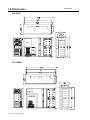
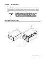
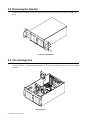
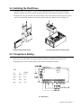
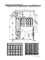
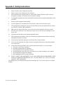
SPC-520 Rackmount Server PC Copyright Notice This document is copyrighted, September 1999 , by Advantech Co., Ltd. All rights are reserved. Advantech Co., Ltd. reserves the right to make improvements to the products described in this manual at any time without notice. No part of this manual may be reproduced, copied, translated or transmitted in any form or by any means without the prior written permission of Advantech Co., Ltd. Information provided in this manual is intended to be accurate and reliable. However, Advantech Co., Ltd. assumes no responsibility for its use, nor for any infringements of the rights of third parties which may result from its use. Acknowledgments SPC-520, SPC-520MB, SPC-520P4, SPC-520P7, SPC-520MB-UW, SPC-520MB-U2 series and PCA6109P4, PCA-6109P7 are the trademark of Advantech Co., Ltd. NOTE: The information in this document is provided for reference only. Advantech does not assume any liability arising out of the application or use of the information or products described herein. This manual is subject to change without notice. Part No. 2002052000 Printed in Taiwan 1st Edition October 1999 Contents Chapter 1 General Information .................................................................. 1 1.1 Introduction ................................................................................................................. 1 1.2 Model List .................................................................................................................. 1 1.3 Specifications ............................................................................................................ 1 1.4 Dimensions ................................................................................................................ 4 Chapter 2 System Setup ............................................................................ 5 2.1 Removing the Cover .................................................................................................. 5 2.2 Removing the Handles ............................................................................................... 6 2.3 The Cooling Fans ....................................................................................................... 6 2.4 Installing the Disk Drives ............................................................................................. 7 2.5 Temperature Setting .................................................................................................. 7 2.6 Installing the Power Supply Unit .................................................................................. 8 Appendix A Passive Backplane ...................................................................................... 9 Appendix B Exploded Diagram s ..................................................................................... 10 Appendix C Safety Instructions ...................................................................................... 12 Chapter 1 General Information 1.1 Introduction The SPC-520P7 / SPC-520MB are PC/AT-compatible computer designed for high relibility applications, not only easily installation and maintain for mission critical applications and harsh environment use, is a high-end rackmount Fault Resilient IPC chassis. The SPC-520P7 includes a 7PCI/1ISA/1PICMG-slot PC-bus compatible passive backplane and 400-watt ATX redudnant power supply. The SPC-520MB can be installed ATX mother board and includes one 400-watt ATX power supply. Both SPC-520P7/MB provide three hot-swappable fan cooling system and accepts up to ten front-accessable half-heigh disk drives. SPC-520P7/MB feature an advanced fault detection and alarm notification system to monitor its own hardware status. It is dangerous and will cause a lot of loss if your PC system shuts down without any warning in advance. 1.2 Model List Mo d el N u m b er B ac k p l an e 400-w at t AC -D C Po w er Su p p l y SPC -520P7 7PC I / 1ISA / 1PIC MG -slot 400-watt ATX Redudnant Power Supply SPC -520MB *** (Reserve the space for ATX Mother board ) 400-watt ATX Power Supply (PS/2 si ze) 1.3 Specifications Construction: Heavy-duty steel chassis Disk drive capacity: Front-accessible eight half-height drives (vertical), and two half-height drives (Horizontal) Cooling system: Three 86 CFM cooling fans inside the chassis Controls: Power On/Off switch on power supply module in rear panel, Alarm Reset botton, ATX Soft-Switch and system reset botton on the front panel Indicators: Bi-color LEDs (green and red) for Power failure, fan failure and overheating. LED indicator (green) for system power on/off. Buzzer: One buzzer for audio alarm / volumn control on board Dimensions: 19"(W) x 8.75"(H) x 26"(D), 482mm(W) x 222.25mm(H) x 660mm(D) Net Weight: RAID-520MB : 37.4 lb (17 Kg), RAID-500P7 : 44 lb (20 Kg) Paint color: (Front panel) Pantone Black 4C 2X, (Chassis) Brushed finish, Ni Operating temperature: 0 to 50oC (32 to 122oF) Relative humidity: 20% to 90% CE Compliant SPC-520 User's Manual 1 Passive Backplane: PCA-6109P7 (for SPC-520P7) Slots: 1 ISA/7 PCI/1 PICMG-slot PC Board: 4-layer PCB with ground and power planes for reduced noise and ower power supply impedance Indicators: LEDs for +3.3V, +5 V, -5 V, +12 V and -12 V Hot-swappable AC-DC 400-watt ATX Redundant Power Supply (RPS-400ATX) Output rating: 400 watts (Max.) Input voltage: 90 to 132 VAC or 180 to 264 VAC @ 47~63 Hz, switchable Output voltages: +5 V @ 42 A, +3.3V @ 20A, +12 V @ 14 A, -5 V @ 1 A, -12 V @ 1 A +5Vsb @ 0.75A (+5V /+3.3V Total: 210Watt) Minimum load: +5 V @ 2 A, +3.3V @ 0.3A, +12 V @ 0.5 A MTBF: 100,000 hours at 25oC, 70% Load Safety: UL/C-UL/TUV/CE Approved AC-DC 400-watt ATX Power Supply PS/2-size (PS-400ATX) Output rating: 400 watts (Max.) Input voltage: 90 to 132 VAC or 180 to 264 VAC @ 47~63 Hz, switchable Output voltages: +5 V @ 42 A, +3.3V @ 20A, +12 V @ 14 A, -5 V @ 1 A, -12 V @ 1 A +5Vsb @ 0.75A (+5V /+3.3V Total : 210Watt) Minimum load: +5 V @ 2 A, +3.3V @ 0.3A, +12 V @ 0.5 A Minimum load: +5 V @ 3 A, +12 V @ 1 A MTBF: 100,000 hours at 25oC, 70% Load Safety: UL/C-UL/TUV/CE Approved 2 SPC-520 User's Manual Fault Detection and Alarm Notification Power failure: It works only when you install the redundant power supply (RPS-400ATX) If either of the two power modules fails, the dedicated LED (PWR) changes color from green to red also audio alarm. The dedicated LED remains red for failed power module until it fixed. Fan failure: If either of the three cooling fans fails, the dedicated LED (Fan 1 or Fan 2) changes color from green to red also audio alarm. The dedicated LED remains red for failed fan set until it fixed. The fan ass'y can be hot-swap if either fan is fail Dual fans for redundant application High Temperature: If the chassis interior temperature exceeds 65oC(149oF)(standard setting), the LED changes color from green to red also audio alarm. The LED remains red until the temperature goes below 63oC Temperature Select: The temperature can be set on four status by adjust the switch on alarm board : 65oC (Default setting) , 55oC , 70oC and 75oC Audible Alarm: Buzzer on board is activated (continous beep)as soon as a malfunction is detected and sounds until the alarm reset button is pressed. The alarm reset button is on the front panel. However, the alarm indicator will stay red until the fault condition is resolved. Self-Test: Press the Alarm reset button for 8 senconds, the alrm board will self-test automatically for all functions. The alarm board also can monitor the temperature's sensor IC. If the sensor is failed or no connection, the buzzer will alarm as " Beep x Beep x ...". The Controls for System The SPC-520 provides one soft-switch and one system reset botton to re-boot the PC system on the front panel. See figure as following : Soft Switch System Reset Botton SPC-520 User's Manual 3 1.4 Dimensions SPC-520P7 SPC-520MB 4 SPC-520 User's Manual Unit = mm Chapter 2 System Setup The SPC-520 is a ATX-compatible computer designed for industrial applications. This rugged chassis meets the EIA RS-310C 19" rackmount standard. Setting up your SPC-520 requires only a screwdriver and a small amount of time. Before you begin, you should also gather together all of the cards you plan to install, as well as the disk drives you plan to use. WARNING: Disconnect all power from the chassis before you install the CPU cards. Unplug the power cord from the wall, don't just turn off the power switch. If you are not sure what to do, take the job to an experienced professional. 2.1 Removing the Cover There are screws near the top along the sides and on the rear secure the cover to the chassis. Remove them, and then slide the cover toward the rear chassis. See figure 2.1 below: 2.1 Remov the cover SPC-520 User's Manual 5 2.2 Removing the Handles The handles and mounting ears for the front panel can be removed as follows. Please see figures 2.2 below 2.2 Removing the handles 2.3 The Cooling Fans There are three cooling fans inside the chassis. To replace the fans for maintainence : open the top cover as the figure 2.1 and loosen the thumbscrews, then plug the whole fan ass'y. please refer to figure 2.3 below. 2.3 Cooling fans 6 SPC-520 User's Manual 2.4 Installing the Disk Drives 1. Open the top cover as figure2.1. There are two independent disk drive bays on the both sides. Remove the four outer screws which mount the drive-bay to the chassis. See figure 2.4 below 2. Slide the drive-bay toward the rear chassis and lift it free of the chassis. Remove the cover of the drive bay front and insert the drives into their proper locations in the drive bay. See figure 2.5 2.4 Removing the disk drive bay 2.5 Inserting the drives into the drive bay 2.5 Temperature Setting If the chassis interior temperature exceeds 65oC(149oF)(default setting), the LED changes color from green to red also audio alarm. The LED remains red until the temperature goes below 63oC Temperature also can be selected (SW1) on the alarm board inside the chassis : SW1 1 2 TEMP OFF OFF 65oC OFF ON 55oC ON OFF 70oC ON ON 75oC 2.6 Alarm board SPC-520 User's Manual 7 2.6 Installing the Power Supply Unit 2.7 ATX power supply (SPC-520P7) 2.8 ATX Redundant power supply (SPC-520MB) 8 SPC-520 User's Manual Appendix A Passive Backplane Unit = mm PCA-6109P7: 7 PCI / 1 ISA / 1 PICMG-slot Backplane Dimensions: 260 x 200 mm ATX PCICPU PIN&NET PCI PIN IDSEL PCI1 NET AD31 INTB INTC INTD INTA J1 P in De s c rip tio n P in De s c rip tio n P in De s c rip tio n 1 +3.3V 11 +3.3V 1 +5V sb 2 +3.3V 12 -12V 2 GND 3 GND 13 GND 3 P S -ON P in De s c rip tio n P S -ON PCI2 NET AD30 INTC INTD INTA INTB 4 +5V 14 P S -ON PCI3 NET AD29 INTD INTA INTB INTC 5 GND 15 GND PCI4 NET SAD20 INTA INTB INTC INTD 6 +5V 16 GND 1 7 GND 17 GND 2 PCI5 NET SAD21 INTB INTC INTD INTA PCI6 NET SAD22 INTC INTD INTA INTB PCI7 NET SAD23 INTD INTA INTB INTC J2 8 (NC ) 18 -5V 9 +5V sb 19 +5V 1 P 1/P 2 GND 10 +12V 20 +5V 2 +12V SPC-520 User's Manual 9 Appendix B Exploded Diagrams SPC-520P7 10 SPC-520 User's Manual SPC-520MB SPC-520 User's Manual 11 Appendix C Safety Instructions 1. Please read these safety instructions carefully. 2. Please keep this User's Manual for later reference. 3. Please disconnect this equipment from AC outlet before cleaning. Don't use liquid or sprayed detergent for cleaning. Use moisture sheet or cloth for cleaning. 4. For pluggable equipment, the socket-outlet shall be installed near the equipment and shall be easily accessible. 5. Please keep this equipment from humidity. 6. Lay this equipment on a reliable surface when install. A drop or fall could cause injury. 7. The openings on the enclosure are for air convection hence protect the equipment from overheating. DO NOT COVER THE OPENINGS. 8. Make sure the voltage of the power source when connect the equipment to the power outlet. 9. Place the power cord such a way that people can not step on it. Do not place anything over the power cord. 10. All cautions and warnings on the equipment should be noted. 11. If the equipment is not used for a long time, disconnect the equipment from mains to avoid being damaged by transient overvoltage. 12. Never pour any liquid into opening, this could cause fire or electrical shock. 13. Never open the equipment. For safety reason, the equipment should only be opened by qualified service personnel. 14. If one of the following situations arises, get the equipment checked by a service personnel: a. The power cord or plug is damaged. b. Liquid has penetrated into the equipment. c. The equipment has been exposed to moisture. d. The equipment does not work well or you cannot get it to work according to user's manual. e. The equipment has dropped and damaged. f. If the equipment has obvious sign of breakage. 15. DO NOT LEAVE THIS EQUIPMENT IN AN UNCONDITIONED ENVIRONMENT, WITH STORAGE TEMPERATURES BELOW -20oC (-4oF) OR ABOVE 60oC (140oF), AS IT MAY DAMAGE THE EQUIPMENT. The sound pressure level at the operator's position according to IEC 704-1:1982 is equal to or less than 70dB(A). 12 SPC-520 User's Manual