1
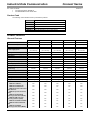
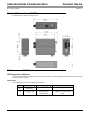
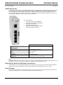
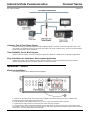
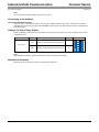
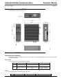
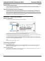
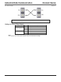
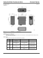
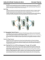
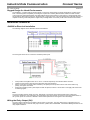
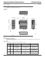
Industrial Data Communication Doc. Code: CE125000 Connect Series Revision: A Product Description Connect Series provides a complete Industrial Data Communication (IDC) portfolio for Fast Ethernet connectivity. Designed as the ideal solution for industrial applications, connecting Programmable Controllers (PLCs), Human-Machine Interfaces (HMIs), Frequency Inverters and supervision stations running on industrial servers or computers, Connect Series delivers a selection of managed and unmanaged switches and Ethernet copper to fiber converter. The easy installation procedures, DIN rail mounting, and a superior rugged design for harsh environment applications, Connect Series supports a high temperature range that ensures reliable operation with 2.0 Gbps, Additionaly, its high performance switching engine and other mechanisms as packet forwarding and filtering fulfills all industrial data communication requirements.. Connect Series also provides network redundancy with secure and reliable data transmission performance, using a ring technology that is capable of recovery from network failures in just 5 ms. As an option, for redundant applications,to avoid interference or even to to extend the network coverage, it is possible use the multi-mode fiber for 2,000 m. Many other smart features as discovery of devices, automatic network topology mapping, configurable output relay for port link loss diagnostic events, support of redundant power supply inputs, various DHCP functions including DHCP Client and Server, make Connect Series the ideal solution for industrial data communication. Ordering Information JC1301 Included Items The product package contains following item: One JC1301-m converter JN2005 Included Items The product package contains following item: One JN2005 switch JN3008 Included Items The product package contains following item: One JN3008 switch with DIN rail clip JN3008f Included Items The product package contains following item: One JN3008f-m switch with DIN rail clip JN4508f-m Included Items The product package contains the following items: Altus S. A. 1 Industrial Data Communication Connect Series Doc. Code: CE125000 Revision: A One managed switch JN4508f-m One RS232 DB9 to RJ45 serial cable Product Code The following codes should be used to purchase the products: Code Description JC1301-m Ethernet/Fiber Converter JN2005 Industrial 5 Ports Switch JN3008 Industrial 8 Ports Switch JN3008f-m Industrial 6 Ports, 2 Fibers Switch JN4508f-m Industrial Managed 6 Ports, 2 Fibers Switch Product Features General Features JN4508f-m JN3008f-m JN3008 JN2005 JN1301-m Number of RJ45 ports 6 (10/100TX) 6 8 5 1 Number of fiber ports 2 (100FX) 2 (100FX) - - 1 (100FX) Multi-mode fiber support Yes Yes No No Yes 2 x 24 Vdc (10 to 60 Vdc) 2 x 24Vdc (10 to 60 Vdc) 2 x 24 Vdc (10 to 60 Vdc) 24 Vdc (18 to 32 Vdc) 18 to 32 Vdc 18 to 27 Vac Polarity auto reverse protection Yes Yes Yes Yes Yes Redundant power supply inputs Yes Yes Yes No No Power supply inputs Relay alarm Insulation Power dissipation Quality of Service (QoS) Yes Yes Yes Yes No 1500 Vac 1500 Vac 1500 Vac 1200 Vac 1500 Vac 15 W 6W 3W 3W 3.5 W Yes Yes Yes No No Operating temperature -10 to 70°C -25 to 75°C -34 to 70°C -25 to 75°C -10 to 70 °C Storage temperature -40 to 85 °C -40 to 85 °C -40 to 85 °C -40 to 85 °C -40 to 80 °C 0 to 95% 0 to 95% 0 to 95% 0 to 95% 0 to 95% DIN rail Relative humidity (noncondensing) Installation options DIN rail DIN rail DIN rail DIN rail Aluminum case Yes Yes Yes Yes Yes IP level IP31 IP31 IP31 IP31 IP31 Dimensions (W x D x H) 53 x 105 x 135 mm 55 x 118 x 128 mm 55 x 108 x 128 mm 30 x 98 118 mm 30 x 98 x 76 mm Package dimensions (W x D x H) 345 x 242 x 82 mm 235 x 150 x 73 mm 235 x 150 x 73 mm 173 x 145 x 65 mm 173 x 145 x 65 mm 885 g 575 g 555 g 290 g 292 g IEEE 802.3 10Base-T Yes Yes Yes Yes Yes IEEE 802.3u 100Base-TX Yes Yes Yes Yes Yes IEEE 802.3u 100Base-FX Yes Yes No No Yes IEEE 802.3x Flow Control and Back-Pressure Yes Yes Yes Yes Yes IEEE 802.1p Class of Service (CoS) Yes Yes Yes No No IEEE 802.1D-2004 Rapid Spanning Tree Protocol (RSTP) Yes No No No No IEEE 802.1AB Link Layer Discovery Protocol (LLDP) Yes No No No No Weight Standards IEEE 802.1Q VLAN and GVRP Yes No No No No IEEE 802.1QinQ and Private LAN Yes No No No No IEEE 802.1s Multiple Spanning Tree Protocol (MSTP) Yes No No No No Altus S. A. 2 Industrial Data Communication Connect Series Doc. Code: CE125000 Revision: A IEEE 802.3ad Link Aggregation Protocol (LACP) Yes No No No No IEEE 802.1x Port Based Network Access Protocol Yes No No No No IEEE 1588 Precision Time Protocol (PTP) Yes No No No No Modbus TCP/IP Yes No No No No ITU-T G.8032 ERPS Yes No No No No Store and forward switch technology 32 Gbps 2 Gbps 2 Gbps 3.2 Gbps - System throughput 26 Mpps 1.49 Mpps 1.49 Mpps 1.49 Mpps - 1 Mb 448 Kb 448 Kb - - 8,000 MACs 2,000 MACs 2,000 MACs - - 661,248 hours 903,014 hours 1,285,382 hours 818,646 hours 506,819 hours Yes Yes Yes Yes Yes CE/FCC CE/FCC CE/FCC CE/FCC/UL CE/FCC Packet buffer MAC address table MTBF - MIL-HDBK-217F GB standard RoHS directive Regulatory approvals CE/FCC/UL Altus S. A. 3 Industrial Data Communication Connect Series Doc. Code: CE125000 Revision: A JC1301-m Description JC1301-m is a compact 1 port Fast Ethernet media converter designed to be compact, which makes it the ideal model that would physically fit into a chassis with limited space, eg machinery control box and duct assembly room. It also supports switch forwarding mode with abnormal packet filtering and pure converter mode for extreme low latency requirement. For example, requirements of EtherCAT protocol, for easy maintenance and time saving, JC1301-m features remote Link Loss Forwarding (LLF) technology which provides remote link loss signal forwarding, acknowledging link events occurred on each end of JC1301-m to main server. To activate forwarding mode and LLF functions, simply adjust DIP switch settings and reset the converter, and the reconfigurations will be applied. For the field site harsh environment installation such vibrating machinery or duct assembly room, JC1301-m can be easily mounted directly onto DIN rail. With the IP grade 31 and rigid alloy case, JC1301-m can withstand a wide temperature range, severe electromagnetic interference and vibration. Its main features are: Dual forwarding modes: switching and pure converter High isolation voltage support Supports Auto MDI/MDI-X and Auto Negotiation Supports Multi-mode (2 Km) Auto Link Loss Forwarding (LLF) for fault detection Extreme low data forwarding latency Dual modes for power input Aluminum case with IP31 grade protection Supports single fiber transmission - WDM Extended operating temperature LED for power and communication diagnostics JC1301-m Available modes Switch mode Pure converter mode Connectors Ethernet port RJ45 Fiber port Duplex SC Power input 2 Pins removable terminal block Diagnostic LED PW Power Input status TP RJ45 port traffic status FX Fiber port traffic status DIP switch configuration DIP1 LLF settings (enable/disable) DIP2 Speed settings (auto-negotiation or forced 100 Mbps full duplex) DIP3 Fiber port settings (full duplex or half duplex) DIP4 Operating mode (pure converter or switch mode) Notes: Available modes: The switch mode will begin to forward the received data only after it received the frame completely. The forwarding latency depends on the packet length and the packet length support 64 to 1600 bytes. The pure converter operating algorithm is different from switch mode. It will direct transfer Ethernet signal without any frame checking. Connectors: RJ45 connector supports category 3, category 4, category 5, unshielded twisted pair or shielded twisted pair cable. The link distance is maximum of 100 meters. SC connector supports multi-mode fiber, 50/125 um or 62.5/125 um, max. distance of 2,000 m. 2 pins terminal block for power input with auto polarity reverse. Switch Mode and Pure Converter Mode The JC1301-m can be used in two different modes, switch mode and pure converter mode. The store-and-forward technology is implemented in switch mode. It will filter out abnormal packets to maintain network efficiency and supports the data forwarding rate up to 148,810 pps (packtes per second) in full wire speed with packet length from 64 to 1522 bytes. In the pure converter mode, the JC1301-m only converts signal between copper and fiber port without any packet check, and operates in the speed of minimum data forwarding latency. Altus S. A. 4 Industrial Data Communication Doc. Code: CE125000 Connect Series Revision: A Traditionally, media converter is used for the signal conversion between electronic and optical. Most of media converters are not capable of handling all kinds of packet sizes. A major drawback is that they cannot support 10/100 Mbps auto negotiation and auto detection function for the cross-over or straight cable. The pure converter mode has the advantage of supporting extreme low transfer latency, even when the packet is with a CRC error, and when the packet length is below 64 bytes. Some of special devices need pure converter and they need it to operate simply without any features. JC1301-m can be configured between the two modes by a DIP switch. For CSMA/CD compliance, the UTP port supports 100 Mbps full duplex when setting JC1301-m as pure converter. If setting as 100 Mbps half duplex mode, the available link distance will be 60 m only. In the switch mode, it will not have this limitation: the link distance can be reached up to 100 m. In pure converter mode, the JC1301-m will operate with the minimum latency of 1.6 micro second. The 2 ports of JC1301m are inter-connected via MII signals, therefore the internal switch MAC and packet buffer are not used. Besides, the packet length will not be limited and will reach up to 1.600 bytes. The updated configuration will be available after resetting the device. Usage Examples The next examples ilustrates diferente architectures that JC1301-m can be used to provide long distances between devices. The first figure shows a PLC communicating with a SCADA system. The next example shows the communication between two half clusters that forms a redundant PLC. Each side of the redundancy can be placed far from each other using JC1301-m, attending to the system disposal issues. The example of I/O expansion, shows that is possible to expand the architecture in long distances from the local rack, distributing the I/O racks according to the system needs. Auto Fault Detection through Link Loss Forwarding When using traditional fiber converters, users often encounter the following problem: a fiber converter acting like an ordinary unmanaged 2 port switch. When one of the fiber converter's ports fails (e.g. the TX port), the other one (e.g. FX port) continues to receive data via the media (e.g. fiber), confusing the device on the other end of the media by indicating that the connection is still intact. But, by the time the disconnection is found, this error causes a great amount of loss. If a port loses the connection for any reason, it will activate Link Loss Forwarding to shut down the other port, as a result, allowing the device on the other end of the media to detect the disconnection. The administrator over the network can be informed of the disconnection immediately, and can react promptly to the situation, greatly reducing loss caused by any link failure. Altus S. A. 5 Industrial Data Communication Doc. Code: CE125000 Connect Series Revision: A The Real Time Ethernet Solution - EtherCAT Test JC1301-m, a has passed the system test of an open real-time Ethernet solution, EtherCAT. For communication tasks, not only the defined latency (cycle time) is important, but the jitter also has to be limited. There is no jitter between two JC1301m converters connected via fiber end, whereas EtherCAT devices attached to the other Ethernet end system. The system meet all requirements of EtherCAT protocol. Reliable Mechanical Design Industrial applications are known as harsh environments and are required to run non-stop. The product is designed for rugged conditions, such as high or low temperature conditions, impact, vibration, or corrosion. To cope with demanding industrial environments, the aluminum alloy case is rigidand conforms to IP31 housing design. Installation - JC1301-m Electrical Installation The following diagram shows JC1301-m electrical installation. 1 - There is one grounding screw on the bottom side of JC1301-m connect the earth ground screw of JC1301 to the grounding surface to ensure safety and prevent noise. 2 - Insert the positive and negative wires into the V+ and V- contact on the terminal block connector. 3 - Tighten the wire-clamp screws to prevent the power wires from being loosened. Note: The recommended working voltage is 24 Vdc (18 to 32 Vdc) or 18 Vac (18 to 27 Vac). Connecting to the Network Connecting the Ethernet Ports Connect one end of an Ethernet cable into the UTP port of JC1301-m, while the other end is connected to the attached networking device. UTP port support auto MDI/MDIX function. Refer to the LED Indicators section for descriptions of each LED indicator. Connecting the Fiber Port Connect the fiber port on JC1301-m to another fiber ethernet device, by following the figure below. Wrong connection or fiber cable type will cause the fiber port not working properly. ATTENTION: This is a Class 1 Laser/LED product. Do not stare into the Laser/LED beam. Altus S. A. 6 Industrial Data Communication Connect Series Doc. Code: CE125000 Revision: A The table below illustrates fiber transceivers specification. Fiber (µm) Connector Wave length (µm) TXPrw (Min) TXPwr (Max) RXPwr (Min) RXPwr (Max) Link Budg (dBm) Distance (Km) Multi-Mode 50 to 62.5/125 SC 1310nm -20 dBm -14 dBm -31 dBm 0 dBm 11 2 Notes: TXPrw (Min): Minimum Launch Power. TXPwr (Max): Maximum Launch Power. RXPwr (Min): Minimum Receive Sensitivity. RXPwr (Max): Maximum Receive Sensitivity. Link Budget: Minimum Launch Power – Maximum Receive Sensitivity. To ensure your fiber converter can transmit/receive data between the 2 nodes, the attenuation of the optical fiber cable should be smaller than the fiber converter’s link budget. Settings for Alarm Relay Output The DIP-Switch pins are described in the next table: Dip Switch Pin Nr. Status Description ON Enable link loose forwarding function OFF Disable link loose forwarding function ON Set RJ45 in 100Mbps full duplex mode OFF Set RJ45 in auto-negotiation mode ON Set fiber port in half-duplex mode OFF Set fiber port in full duplex mode ON Set JC1301-m in pure converter mode OFF Set JC1301-m in switch converter mode Default Alarm Switch Pin1 X Pin2 X Pin3 X Pin4 X Note: After adjusting the DIP-switch, please reboot the conversor to activete the new settings. Mechanical Assembly Mount the din-rail clip screwed on the rear of JC1301-m on the DIN rail. Altus S. A. 7 Industrial Data Communication Connect Series Doc. Code: CE125000 Revision: A Physical Dimensions- JC1301-m The dimensions of module are shown in mm. Maintenance - JC1301-m LED Diagnostic Indicators The conversor has LEDs to indicate the status of the communication. The following tables show the meaning of each state and a respective description Power Input The LED PW (green color) is described in the next table: Altus S. A. Green Description Causes Solution On Normal use - - Off LED fail or module off Disconnected module. No external supply or hardware failure Check if the module is completely supplied by an external power supply 8 Industrial Data Communication Connect Series Doc. Code: CE125000 Revision: A RJ45 Port The LED TP (green color) is described in the next table: Green Description Causes Solution On Indicates the module has Link - - Blinking Indicates the module has Activity Off LED fail or module off Disconnected module cable. No external supply or hardware failure Check if the module is completely supplied by an external power supply or check if the cable is connected Fiber Port The LED FX (green color) is described in the next table: Altus S. A. Green Description Causes Solution On Indicates the module has Link - - Blinking Indicates the module has Activity - - Off LED fail or module off Disconnected module cable. No external supply or hardware failure Check if the module is completely supplied by an external power supply or check if the cable is connected 9 Industrial Data Communication Connect Series Doc. Code: CE125000 Revision: A JN2005 Description The JN2005 is an Industrial 5 port 10/100BaseTX Ethernet switch. JN2005 adopts slim industrial design to save rail space for compact systems. In order to survive under harsh environment, JN2005 features an industrial-grade aluminum case with IP31 grade protection ability against dust and water. JN2005 provides one relay output for port link down events, which is enabled / disabled by the DIP switch. Moreover, JN2005 has good immunity against unstable power source and can accept input voltage from 18 Vdc to 32 Vdc on its terminal block. Its main features are: 5 ports 10/100TX with auto MDI/MDI-X Slim-sized for industrial din-rail application Relay output for port alarm High isolation voltage support Aluminum case with IP31 grade protection Extended operating temperature JN2005 Connectors Ethernet ports RJ45 Power input 4 pins removable terminal block Diagnostic LED P Power input status Alm Alarm status P1 to P5 RJ45 port traffic status DIP switch configuration DIP 1 to 5 Enable/Disable port link down alarm event Note: Connectors: RJ45 connector category 3, category 4, category 5 unshielded twisted pair or shielded twisted pair cable. The link distance is maximum 100 meters. Terminal block for power input with auto polarity reverse. Plug-and-Play Switch & High-Speed Transmission JN2005 requires no user setup and immediately starts operating as soon as you power it up. Excellent data transmission performance is provided for applications. No traffic will be delayed with the transmission rate up to 3.2 Gbps. Usage Example The next example ilustrates an architecture that JN2005 can be used to provide communication between many devices in the network. The figure shows a communication with PLCs, HMI and SCADA system. Altus S. A. 10 Industrial Data Communication Doc. Code: CE125000 Connect Series Revision: A Compact Size & Fault Relay Output The slim sized design makes it an ideal model that would physically fit in a network environment with limited space. One relay output is an important feature to let you know when there is any event of port link down. Just move up the DIP switch and the fault relay alarm will be operational. True Reliability for the Best Support With the 1500 Vdc isolation protection and regulatory approvals, JN2005 is a reliable choice for hazardous applications. Easy Installation for Hazardous Environment Application JN2005 can be easily wall mounted and mounted directly on DIN rail. The IP31 rigid aluminum flat casing and wide operation temperature range ensure reliable operation for harsh environment. Installation - JN2005 Electrical Installation The following diagram shows JN2005 electrical installation. 1 - There is one grounding screw on the bottom side of JN2005. Connect the earth ground screw of JN2005 to the grounding surface to ensure safety and prevent noise. 2 - Insert the positive and negative wires into the V+ and V- contact on the terminal block connector. 3 - Tighten the wire-clamp screws to prevent the power wires from being loosened. 4 - The relay outuput alarm contacts are indicated in the terminarl block connector as shown in the figure. Relay output carry ability 1 A at 24 V. Set the DIP switch of Port Alarm to “ON”, relay outuput alarm will detect any port failures, and form a short circuit. The alarm relay output is “Normal Open”. Altus S. A. 11 Industrial Data Communication Connect Series Doc. Code: CE125000 Revision: A Note: The recommended working voltage is 24 Vdc (18 to 32 Vdc). Connecting to the Network Connecting the Ethernet Ports Connect one end of an Ethernet cable into the UTP port of JN2005, while the other end is connected to the attached networking device. All UTP port support auto MDI/MDIX function. Refer to the LED Indicators section for descriptions of each LED indicator. Settings for Alarm Relay Output Enable or disable by a DIP-switch the relay output when a port link down event occurs. The next table shows how the configuration works. Dip Switch Pin Nr. Status Description ON Enable port link down alarm event at this port OFF Disable port link down alarm event at this port Default Alarm Switch Pin 1 to Pin 5 X Note: After adjuting the DIPswitch, please reboot the the switch to activate the new settings. Mechanical Assembly Mount the din-rail clip screwed on the rear of JN2005 on the DIN rail. Altus S. A. 12 Industrial Data Communication Connect Series Doc. Code: CE125000 Revision: A Physical Dimensions - JN2005 The dimensions of module are shown in mm. Maintenance - JN2005 LED Diagnostic Indicators The switch has LEDs to indicate the status of the communication. The following tables show the meaning of each state and a respective description. Power Input The LED P (green color) is described in the next table: Green Description Causes Solution On Normal use - - Off LED fail or module off Disconnected module. No external supply or hardware failure Check if the module is completely supplied by an external power supply Alarms The LED Alm (red color) is described in the next table: Red Altus S. A. Description Causes Solution 13 Industrial Data Communication Connect Series Doc. Code: CE125000 On Off Revision: A Port link down event At least one port is configured and have triggered link down event Check if the cables of P1 to P5 ports is disconnected. Normal use or LED fail Normal operation or link down events are disabled or module has no external power supply or hardware failure Check the power supply connector is connected. Check if the wires are properly connected in the power supply connector. Check if the external power supply is working properly RJ45 Port The LEDs LNK (green color) and ACT (yellow color) of RJ45 port are described in the next table: Green Altus S. A. Yelow Description Causes Solution On Off Indicates the module has100 Mbps link - - Off On Indicates the module has 10 Mbps link - - Blinking On/ Blinking Indicates the module is active and link 100 Mbps - - Off Blinking Indicates the module is active and Link 10 Mbps Off Off LED fail or module off Disconnected module cable. No external supply or hardware failure Check if the module is completely supplied by an external power supply or check if the cable is connected 14 Industrial Data Communication Connect Series Doc. Code: CE125000 Revision: A JN3008/JN3008f-m Description The JN3008 is an 8 port fast Ethernet switch to best fit in heavy industrial field applications and the JN3008f-m is an 8 port fast Ethernet switch designed with 6 RJ45 fast Ethernet copper and 2 fast Ethernet fiber ports to best fit in long distance heavy industrial field applications. Both switches have an enhanced design specification, including wider operation temperature and power input range. They are equipped with 2.0 Gbps high performance switching engine with packet forwarding and filtering mechanism to fulfill higher performance industrial data communication requirements in field site deployments. The packet forwarding feature enables the JN3008 to handle from 64 to 1522 bytes packet sizes into 2 forwarding priority queues which is compliant with IEEE 802.1p Class of Service (CoS) for providing best data performance. Both have broadcast storm filtering and flow control functions that can ensure data traffic delivery to destination without traffic congestion. The combination of enhanced network features and rugged specifications, make the JN3008/JN3008f-m the best entry-level networking solution in industrial deployments. Its main features are: 8 ports 10/100 Base TX with Auto MDI/MDI-X (only JN3008) 6 ports 10/100 Base TX plus 2 Fast Ethernet fiber ports (only JN3008f-m) Supports Multi-mode (2 Km, only JN3008f-m) Compact size with full power redundancy Excellent data exchange performance QoS for packet forwarding precedence Broadcast storm packet filtering Port and power event alarm Dual power inputs with redundancy High isolation voltage support Aluminum case with IP31 grade protection Extended operating temperature JN3008 / JN3008f-m Broadcast storm control Default enabled Connectors Ethernet ports RJ45 Fiber port (only JN3008f-m) Duplex SC Power input / relay 6 pins removable terminal block Diagnostic LED PWR1, PWR2 Power input status (redundant) Alm Alarm status LNK/ACT - 7, 8 (only JN3008f-m) Fiber port traffic status 1 to 8 (JN3008) or 1 to 6 (JN3008f-m) ports RJ45 port traffic status DIP switch configuration DIP 1 to 5 Enable/Disable port link down alarm event Notes: Broadcast storm control: Traffic threshold 200 packets/s at 100 Mbps; 20 packets/s at 10 Mbps. Connectors: RJ45 connector 10Base-T 2 pairs UTP/STP category 3, category 4, category 5 cable, EIA/TIA_568B 100ohm (100 m) and 100 Base-TX 2-pairs UTP/STP category 5 cable, EIA/TIA-568B 100-ohm (100 m). SC connector supports multi-mode fiber 50/125 um or 62.5/125 um, max. distance 2,000 m. Alarm relay and power input 6 pins removable terminal block with redundant power input with polarity auto reverse protection. Fiber Optic Port Options for Long Distance Requirement To avoid interference as well as to extend the network coverage, in addition to 6 fast Ethernet copper ports, JN3008f-m is equipped with 2 100 Mbps fiber uplink ports, supporting multi-mode fiber for 2,000 m distances, in order to achieve stable far end transmission. Altus S. A. 15 Industrial Data Communication Doc. Code: CE125000 Connect Series Revision: A Reliable Power System Design In order to operate under harsh environment of industrial sites, JN3008 and JN3008f-m are designed with redundant wide power input with extending voltage range as well as auto polarity reverse function to ensure the switch's capability of transmitting data under poor power sourcing. High Electromagnetic Interference Immunity In industrial applications with widespread electromagnetic interference, such as the automation control and high power motor operating environments, the switch's electromagnetic immunity ability will affect the quality of data transfer. The JN3008, compliant with the electromagnetic interference requirements for heavy industrial applications, provides a high level of electromagnetic susceptibility according the IEC/EN 61000-6-2 standard with distinguished electrical slow transient, radio-frequency electromagnetic field and electrical fast transient protections. Equipped with a rugged aluminum case with IP31 grade protection and high thermal conductivity design, it is capable of resisting an extended temperature range while providing reliable connectivity under harsh industrial environments. Installation - JN3008 and JN3008f-m Electrical Installation The following diagram shows JN3008/JN3008f-m electrical installation. 1 - There is one grounding screw on the bottom side of JN3008/JN3008f-m. Connect the earth ground screw of JN3008/Jn3008f-m to the grounding surface to ensure safety and prevent noise. 2 - Insert the positive and negative wires into the PW1+, PW1-, PW2+ and PW2- contacts on the terminal block connector. 3 - Tighten the wire-clamp screws to prevent the power wires from being loosened. 4 - The relay outuput alarm contacts are indicated in the terminarl block connector as shown in the figure. Relay output carry ability 1 A at 24 V. Set the DIP switch of port alarm to “ON”, relay outuput alarm will detect any port failures, and form a short circuit. The alarm relay output is “Normal Open”. Note: The recommended working voltage is 24 Vdc. Connecting to the Network Connecting the Ethernet Ports Connect one end of an Ethernet cable into the UTP port of JN3008/JN3008f-m, while the other end is connected to the attached networking device. All UTP ports support auto MDI/MDIX function. Refer to the LED Indicators section for descriptions of each LED indicator. Connecting the Fiber Port Connect the fiber port on JN3008f-m to another fiber Ethernet device, by following the figure below. Wrong connection or fiber cable type will cause the fiber port to work unproperly. Altus S. A. 16 Industrial Data Communication Connect Series Doc. Code: CE125000 Revision: A ATTENTION: This is a Class 1 Laser/LED product. Do not stare into the Laser/LED beam. Settings for Alarm Relay Output Dip Switch Pin Nr. Status Description ON Enable port link down alarm event at this port OFF Disable port link down alarm event at this port ON Enable power failure alarm OFF Disable power failure alarm Pin 1 to Pin 8 Pin 9 Note: After adjuting the DIP switch, please reboot the device to activate the new settings. Altus S. A. 17 Industrial Data Communication Doc. Code: CE125000 Connect Series Revision: A Mechanical Assembly Mount the din rail clip screwed on the rear of JN3008/JN3008f-m on the DIN rail. Physical Dimensions - JN3008 and JN3008f-m The dimensions of modules are shown in mm. JN3008 Altus S. A. 18 Industrial Data Communication Connect Series Doc. Code: CE125000 Revision: A JN3008f-m Maintenance - JN3008 and JN3008f-m LED Diagnostic Indicators The switches have a LEDs to indicate the status of the communication. The following tables show the meaning of each state and a respective description Power Input The LEDs PWR1 and 2 (green color) are described in the next table: Green Green Description Causes Solution On On Normal use - - Off Module operational, no redundant power supply or LED fail At least one external power supply is off or hardware failure Check if both power supply inputs are completely supplied by an external power supply Off On Module operational, no redundant power supply or LED fail At least one external power supply is off or hardware failure Check if both power supply inputs are completely supplied by an external power supply Off Off LED fail or module off Disconnected module. No external supply or hardware failure Check if the module is completely supplied by an external power supply On Altus S. A. 19 Industrial Data Communication Connect Series Doc. Code: CE125000 Revision: A Alarms The LED Alm (red color) is described in the next table: Red On Off Description Causes Solution Port link down event or power failure occurred At least one port is configured and have triggered link down event or at least one power supply is not connected or not working properly Check if the cables of P1 to P6 or P8 ports are disconnected Check the power supply connector is connected Check if the wires are properly connected in the power supply connector Check if the external power supply is working properly Normal use or LED fail Normal operation or link down events are disabled or module has no external power supply or hardware failure Check if one of PWR1 or PWR2 is turned off. If one of them is off, then the Alm LED is fail RJ45 Port The LEDs LNK (green color) and ACT (yellow color) of RJ45 ports are described in the next table: Green Yelow Description Causes Solution On On Indicates the module has100 Mbps link - - On Off Indicates the module has 10 Mbps link - - Blinking On Indicates the module is active and link 100 Mbps - - Blinking Off Indicates the module is active and link 10 Mbps Disconnected module cable. No external supply or hardware failure Check if the module is completely supplied by an external power supply or check if the cable is connected. Off Off LED fail or module off Fiber Port The LEDs LNK/ACT (green color) of fiber ports are described in the next table: Green Description Causes Solution On Indicates the module has link 100 Mbps - - Blinking Indicates the module is active and link 100 Mbps - - LED fail or module off Disconnected module cable. No external supply or hardware failure Check if the module is completely supplied by an external power supply or check if the cable is connected. Off Altus S. A. 20 Industrial Data Communication Connect Series Doc. Code: CE125000 Revision: A JN4508f-m Description The JN4508f-m is an Industrial managed fast Ethernet switch equipped with 6 ports 10/100 Mbps ports RJ-45 plus 2 100Mbps Fiber uplink ports. Combined the outstanding L2 management features along with the LLDP and high system reliability, including MSR and MSTP network redundancy technologies, for ensuring real-time and high quality connectivity in various networking applications. The JN4508f-m adopted 32 Gbps switch fabric to provide real time non-blocking transmission performance for satisfying the needs of high bandwidth data transmission requiring applications while ensuring traffic switching without data loss. Besides, the new system design includes a hardware based watchdog timer for keeping the operating system live. It also provides power redundancy with wide range voltage Vdc inputs for ensuring the power continuity in the system. With a ruggedized design with IP31 enclosure, JN4508f-m provide highly reliable and secure data transmission under severe industrial environments To build a smart, cost-efficient industrial Ethernet infrastructure, JN4508f -m is the best choice. Its main features are: 6 ports 10/100 Base TX with auto MDI/MDI-X 2 ports 100 Base FX uplink ports Supports multi-mode 2,000 m 32Gbps non-blocking transmission 8000 MAC address table Multiple super ring with recovery time < 5 ms Rapid dual homing Multiple ring MSTP / RSTP SNTP VLAN and private VLAN QinQ, GVRP, QoS, IGMP snooping Rate control and port trunking, LACP Online multi-port mirroring LLDP NMS JetView Pro for auto-topology and group management Supports SNMP Multiple language Web UI Serial Management Supports MODBUS TCP/Client protocol Embedded hardware watchdog for system auto rescue Software configurable alarm output Dual power inputs with redundancy Wide range voltage Vdc inputs High isolation voltage support Aluminum case with IP31 grade protection Extended operating temperature JN4508f-m Altus S. A. System log 1000 entries for system or remote log server DHCP client Yes Supports NMS Yes, Jet View Pro Networking redundancy Yes Multiple super ring Yes Maximum super ring 4 Rapid dual homing Yes Trunk ring Yes IGMP Snooping Yes, V1/V2/V3 and query mode compliance VLAN Port based VLAN, tag VLAN (VLAN ID 1 to 4094) Private VLAN Yes Packet filter Yes SNMP V1/V2c/V3 Yes SNMP MIB MIB-II, Private MIB, Bridge MIB, Ethernet-like MIB, RMON, VLAN MIB, IGMP MIB 21 Industrial Data Communication Connect Series Doc. Code: CE125000 Revision: A SNMP trap Support 4 trap stations SNTP Yes Web browser Yes SMTP Yes Management IP Security Yes Port Security Yes Port mirroring Yes Rate Control Yes Firmware update Yes Reset button System reboot and factory default setting Connectors Ethernet ports RJ45 Fiber ports Dual SC Power inputs/relay Dual 4 pins terminal blocks RS232 console RJ45 Diagnostic LED PWR1 and 2 Power input status (redundant) SYS System operating status R.S Ring operating status DI Digital inputs status (high level signals) DO Digital output status (relay output) LNK / ACT (ports 1 to 8) Fast Ethernet ports 1 to 6 and Fiber ports 7 and 8 traffic and link status Notes: DHCP client: The DCHP (Dynamic host Configuration Protocol) is a TCP/IP protocol service used to configure the host dinamicaly. It provide the IP address, subnet mask, default gateway. The DHCP client is the device capable to receive the TCP/IP configuration from a DHCP server. Supports NMS: The JN4508f-m supports the NMS (Network Management System) – JetView Pro that helps to finding and link topology discovery. Multiple super ring: Ring redundancy technology, includes Rapid Super Ring, Rapid Dual Homing and Trunk Ring. Rapid dual homing: Multiple uplink paths to one or multiple upper swtich. Trunk ring: Integrate port aggregate function in ring path to get higher throughput ring architecture. IGMP snooping: Is the process of listening to IGMP (Internet Group Management Protocol) network traffic. The feature allows a network switch to listen in on the IGMP conversation between hosts and routers. By listeing to these converstaions the switch maintains a mpa of which links need which IP multicast streams. VLAN: Is a logical group of workstation, servers and network devices that appear to be on the same LAN despite their geographical distribution. A VLAN (Virtual Local Area Network) allows a network of computers and users to communicate in a simulated environment. Used to achieve sacalability, security and ease of network management. Private VLAN: Direct client ports in isolated/community VLAN to promiscuous port in primary VLAN. SNMP: Is a popular protocol for network management. The SNMP (Simple Network Management Protocol) is used for collecting information and configuring network devices. SNTP: Is a simplified version of NTP (Network Time Protocol) that is used to synchronize computer clocks on a network. The SNTP (Simple Network Time Protocol) is generally used when full implementation of NTP is not needed. SMTP: Is a TCP/IP protocol used in sending and receiving e-mail. SMTP (Simple Mail Transfer Protocol) is typically used when e-mail is delivered from an email client to an email server or when e-mail is delivered from one e-mail server to another. Management IP Security: IP address security to prevent unauthorized access. Port Security: Port security to assign authorized MAC to specific port. Port mirroring: Online traffic monitoring on multiple selected ports. Rate Control: Ingress filtering for broadcast (broadcast storm control), multicast, unknown DA or all packtes. Egress filtering for all packet types. Fiber Optic for Long Distance Data Transmission To offer enhanced reliability, stability and extended connectivity, JN4508f-m is designed with 2 fiber ports with superior characteristics, including antielectromagnetic interference, anti-moisture and antivibration capabilities. To meet your needs for various distance transmission, the fiber ports support multi-mode fiber with 2,000 m link distance. High Performance The JN450f-m designed with 32 bits processor running at 180 MHz, combines an embedded hardware based watchdog timer to avoid system crashed by environmental factors, such as intense electromagnetic interference, extreme Altus S. A. 22 Industrial Data Communication Connect Series Doc. Code: CE125000 Revision: A temperature variations and/or any wrong instruction looping. This outstanding design can ensure the system stability and reliability when it installed in hardened environment. Advanced L2 Network Control Performance and Security features The JN4508f-m provides various network control and security features to ensure the reliable and secure network connection. To optimize the industrial network environment, the switch supports tag based VLAN, IGMP Snooping, IEEE 802.1s multiple spanning tree, IEEE 802.1w rapid spanning tree, quality of service (QoS), link aggregation control protocol (LACP), rate control, port mirror, etc. allowing users to fully handle. To avoid attacks and ensure the secure data transmission, JN4508f-m features DHCP client, DHCP server with IP and MAC binding, 802.1X access control, SSH for telnet security, IP access table, port security, private VLAN for independent network traffic handling as well as many other security features. MODBUS TCP/IP for Factory Automation Network Enhancement The Modbus TCP/IP protocol is supported in JN4508f-m for factory automation applications. It enables administrator to connect to data acquisition (SCADA) system and read the switch's operating information using its own MODBUS TCP/IP client program for monitoring and maintaining switch’s status. With the supported MODBUS TCP/IP, the JN4508f-m become an element of factory automation such as the programmable logic controller (PLC), distributed control system (DCS), and allow users to monitor/maintain factory equipment on the HMI (Human Machine Interface) system, including production information and communication status. Therefore, user does not need to integrate multiple management platforms to monitor factory equipment: with just a single JN4508f-m platform users can easily achieve enhanced monitoring and maintenance of the entire factory. Easy to Configure Network Managment Interface For easy of configuration and monitoring, the JN4508f-m offers various of management interface , such as SNMP, Web browser, in-band telnet and out-band local serial console with command like interface. The switch status as well as all the networking features can be enabled through these management interfaces. The failure notifications are later sent through e-mail, SNMP trap, local/remote system log, fault event alarm relay. In addition to all these management interfaces, JN4508f-m also supports a network management system (NMS) utility for achieving cost efficiency in system construction, which integrates comprehensive network monitoring features for auto topology discovery, device auto discovery, group IP address change and firmware update. Comprehensive Redundant Solutions – Multiple Super Ring The JN4508f-m supports new generation ring technology, which includes various new technologies for different network redundancy applications and structures. It allows aggregating up to 4 fast Ethernet rings. With the multiple super ring technology, a node can be configured to multiple rings with the failover time in as little as 5 ms and zero-second of restoration time. In addition, users can extend the ring topology by adding hundreds of Connect Series to meet the largescale network needs without compromising the network speed. The multiple super ring also allows the Connect Series to easily connect with core management switches via standard rpid spanning tree protocol or through multiple paths or nodes to increase the reliability by rapid dual homing technology. By integrating multiple super ring and link aggregation control protocol (LACP) the Connect Series can enhance the link availability and increase the overall link capacity. Two or more fast Ethernet connections are combined in order to increase the bandwidth and to create a resilient and redundant link. Rapid Super Ring Technology Rapid super ring is the second generation of ring redundancy technology. The recovery time is greatly improved from 20 ms to few ms for both copper and fiber rings. The ring master can be auto-selected by rapid super ring engine. The first ring port of the ring master is the primary path while the second ring port of the ring master is the block path. Once the primary path fails, the second path will be recovered within few ms. Besides; the restoration time is also shortened to zero in the ring master auto-selection mode. Seamless Ring Port Restoration Seamless restoration is a new technology which can restore a failed ring without causing any loop problem, topology change and packet loss. With zero second restoration time, this mechanism eliminates any unstable status and guarantees the applications running non-stop. Rapid Dual Homing Technology Rapid dual homing is also an important feature of new generation ring technology. It supports ring coupling with other vendors devices. Moreover, providing easy configuration and multiple redundancies, the failover time is much faster and the restoration time is zero ms. Uplinks can be auto detected and gathered into groups. In each group uplinks are sorted into primary, secondary and standbys based on their link speed. The uplink with the highest speed is more likely to be active path for data transmission. Link aggregation is also integrated into rapid dual homing. An uplink connection can be a single link or several links aggregated as a trunk, which provides better redundancy and link capacity. Trunk Ring Trunk ring is a new feature in multiple super ring which merges the two technologies of rapid super ring and link aggregation. It takes advantages of aggregation to enhance the link redundancy, while increasing the link speed. The ring Altus S. A. 23 Industrial Data Communication Connect Series Doc. Code: CE125000 Revision: A will open only if all the aggregated links are broken. Link aggregation can be achieved by either static trunk or LACP. Not all the link sections in a trunk ring need to be the same. Ring links can be either symmetric or asymmetric. Some are a single path, and the others are aggregated by links where the number of links in a trunk group can be different. Users can enhance the link redundancy at different locations in accordance to the need. The link with less speed is more likely to be used as the backup path for restoring the network to full play capacity. Multi Ring The multi ring provides easier connectivity between two ring networks. The simplest example is to connect two rings by a single device. Depending on the number of ports and the speed, the JN4508f-m can connect as a 100 Mbps ring and uplink higher level witch Connect Series industrial switch. As shown in the below figure, multiring technology simply extends the network topology by linking multiple rings into a line or into multiple directions. In addition to extensibility, multi ring has great diversity of various ring technologies. When multi ring enabled, JN4508f-m can connect rapid super ring rings, trunk ring and a super ring together and simultaneously provide more fast Ethernet ring connectivities. This provides extensibility to new technologies while keeping the great backward compatibility. Link Aggregation Control Protocol Link aggregation control protocol allows users grouping multiple Ethernet ports in parallel to increase the link bandwidth. The aggregated ports can be viewed as one physical port, so that the bandwidth is higher than just one single Ethernet port. The member ports of the same trunk group can balance the loading and backup with each other. The LACP feature is usually used when higher bandwidth is needed for the backbone network. This is a cost-effective way for transferring much more data. If the trunk port is also assigned as a ring port, it will become a trunk ring, which means the bandwidth of ring path has increased with port trunk technology. Now, there is no recovery time when failure occurred. The JN4508f-m provides a simple and easy way to aggregate port bandwidth into rapid super ring. Precision Time Protocol The precision time protocol is designed to synchronize time across Ethernet networks. It allows synchronization of distributed clocks to submicrosecond accuracy for devices that may have differing precision, resolution and stability. JN4508f-m supports auto (or bindery clock), master and slave modes for time synchronization to achieve a high level of synchronization within an industrial motion-control environment with a minimum use of network and computing resources. The protocol helps for sequencing event measurements, scheduling outputs, synchronizing actuation, time-stamping, coordinating event records, etc. Auto Topology Discovery & Efficient Management Through LLDP and NMS JN4508f-m supports topology discovery or LLDP (IEEE 802.1AB Link Layer Discovery Protocol) function that can help users to discover multi-vendor’s network devices on the same segment by NMS (Network Management System), which support LLDP function. With LLDP function, NMS can easily maintain the topology map, display port ID, port description, system description, VLAN ID, etc. Once a link failure happens, the topology changed events are updated to the NMS to help users easily maintain the network system. Besides the SNMP and LLDP protocols, JN4508f-m efficiently works with the NMS, which in addition to the auto-topology discovery, also delivers multiple super ring group management, group IP assignment, firmware update, configuration file backup/restore ,SNMP MIB Browser /compile, etc. Furthermore, users can export the topology map to diverse formats, such as JPG, BMP, PNG and PDF, for easily managing and trouble-shooting the network. The user-friendly software allows administrators to discover devices automatically and efficiently manage the performance of the industrial network. Altus S. A. 24 Industrial Data Communication Doc. Code: CE125000 Connect Series Revision: A Rugged Design for Harsh Environments The JN4508f-m, compliant with the electromagnetic conformance requirements of industry applications, provides a high level of electromagnetic susceptibility exceeding the requirements of railway EMC standard, vibration as well as traffic control and heavy-industrial standards' with distinguished electrical slow transient, radio-frequency electromagnetic field, electromagnetic fast transient protection. Equipped with a rugged aluminum case with high thermal-conductivity design, it is capable of resisting a wide temperature ranges while providing reliable connectivity under harsh industrial environments. Installation JN4508f-m JN4508f-m Electrical Installation The following diagram shows JN4508f-m electrical installation. The next figure shows how to connect the redundant power inputs. Insert positive and negative wires into V+ and V- contacts respectively of the terminal block connector. Tighten the wire-clamp screws to prevent DC wires from being loosened. Power 1 and Power 2 support power redundancy and polarity reverse protect function. That means with wrong polarity, the system won’t work. Positive and negative power system inputs are both accepted, but Power 1 and Power 2 must apply with same mode as following figures. Note: The recommended working voltage is 24 Vdc. Remember to unplug the power terminal block before making wire connections. Otherwise, your screwdriver can inadvertently short your terminal connections to the grounded enclosure. If the 2 power inputs are connected, JN4508f-m Switch will be powered from the highest connected voltage. Wiring the Relay Output (DO) The relay output contacts are in the bottom side as shown on the figure. The relay output (DO) is controlled by the predefined operating rules. To activate relay output function, please refer to MU225600 - User Manual Managed Switch for the relay output information. Altus S. A. 25 Industrial Data Communication Doc. Code: CE125000 Connect Series Revision: A Note: The relay contact only supports 1 A current, 24 Vdc. It is not recommended to apply voltage and current higher than the specifications. Wiring the Relay Input (DI) The Digital Input (DI) contacts are in the bottom side of the device as shown in next figure. It accepts one external Vdc type signal input and can be configured to send alert message through Ethernet when the signal is changed Note: The DI accepts Vdc type signal and supports isolated input circuit with digital high level input 11 to30 Vdc and digital low level input 0 to 10 Vdc. Do not apply voltage higher than the specification; it may cause internal circuit damage or a wrong action of DI. JN4508f-m Connecting to the Network Connecting the Ethernet Ports Connected one end of an Ethernet cable into the UTP port of JN4508f-m, while the other end is connected to the attached networking device. All UTP ports support auto MDI/MDIX function. The Ethernet ports will auto-detect signals from connected devices in order to decide the correct link speed and duplex mode. Refer to the LED Indicators section for descriptions of each LED indicator. Connection the Fiber Port Connect the fiber port on your JN4508f-m to another Fiber Ethernet device, by following the figure below. Wrong connection or fiber cable type will cause the fiber port not working properly. Altus S. A. 26 Industrial Data Communication Doc. Code: CE125000 Connect Series Revision: A ATTENTION: This is a Class 1 Laser/LED product. Do not stare into the Laser/LED Beam. JN4508f-m Mechanical Assembly Mount the din-rail clip screwed on the rear of JN4508f-m on the DIN rail. JN4508f-m Management JN4508f-m industrial managed switch provides both in-band and out-band configuration methods. Is possible to configure the switch via the RS232 console with the attached console cable, or remotely manage the switch via network chossing Telnet/SSH, Web/HTTPS management. Preparation for Console Management Attach the RS232 DB9 connector to the PC COM port. Connect the RJ45 connector to the console port of the JN4508f-m Switch. Go to Start -> Program -> Accessories -> Communication -> Hyper Terminal and give a name to the new console connection. Choose the COM name and select the correct serial settings. The serial port settings of JN4508f-m are 9600 bps, No parity check, 8 Data bits, 1 stop bit. After connected, Switch login request will appear. Type the username and password and to login. The default username is "admin", password is "admin". Follow the user manual to configure the software features. Preparation for Web Management Before to use the embedded web interface to manage switch operation, verify that JN4508f-m is properly installed on your network and that every PC on this network can access the switch via the web browser. Launch the web browser on the PC and type http://4508_IP_Address (the default IP address is 192.168.10.1.), then press Enter. The login screen will appear next and type in the user name and password and click "OK" button. The welcome page of the Web-Based management interface will appear then. The default user name and password is “admin”/”admin”. At the left column of the web management interface are the software features, where ring column will list the available settings. For more operating instructions, please refer to the user manual of JN4508f-m. Altus S. A. 27 Industrial Data Communication Connect Series Doc. Code: CE125000 Revision: A Physical Dimensions The dimensions of modules are showing in mm. JN4508f-m Maintenance JN4508f-m LED Diagnostic Indicators The switches have a LEDs to indicate the status of the communication. The following tables show the meaning of each state and a respective description Power Input The LEDs PWR1 and 2 (green color) are described in the next table: Green Green Description Causes Solution On On Normal use - - Off Module operational, no redundant power supply or LED fail At least one external power supply is off or hardware failure Check if both power supply inputs are completely supplied by an external power supply Off On Module operational, no redundant power supply or LED fail At least one external power supply is off or hardware failure Check if both power supply inputs are completely supplied by an external power supply Off Off LED fail or module off Disconnected module. No external supply or hardware failure Check if the module is completely supplied by an external power supply On Altus S. A. 28 Industrial Data Communication Connect Series Doc. Code: CE125000 Revision: A System Alarm The LED SYS (green color) is described in the next table: Green Description Causes Solution On Normal use, ready to operating - - Off LED fail or module off No external supply or hardware failure Check if the module is completely supplied by an external power supply Digital Input (DI) Alarm The LED DI (green color) is described in the next table: green Description Causes On High level signals is applied and detected External equipment set the digital input pins Solution Off Digital input off or LED fail External equipment not set the digital input or module has no external power supply or hardware failure Check if the module is completely supplied by an external power supply or de external equipmente is properly connected to the digital input Digital Output (DO) Alarm The LED DO (red color), related to the relay output, is described in the next table: Red Description Causes Solution Check if the module is completely supplied by an external power supply. Check if the cable is connected Check if one of the pre-defined configured events was achived - On The output is formed close circuit At least one external power supply is off or module has one port link break or hardware failure or one of the switch’s configuration events was achived Off Normal use or LED fail Normal operation or module has no external power supply or hardware failure Ring Status (R.S.) Alarm The LED R.S. (green and yellow colors) is described in the next table: Altus S. A. Green Yellow Description Causes Solution On Off Normal ring use - - Blinking Off Ring port connection Wrong ring port is connected Check the ring port connection Off On Abnormal use Ring fail occurred Check the ring cables and connections Off Blinking Ring path broke One of device’s ring path is broken Off Off LED fail or module off No external supply or hardware failure Check if the module is completely supplied by an external power supply 29 Industrial Data Communication Connect Series Doc. Code: CE125000 Revision: A RJ45 and Fiber Ports The LEDs LNK/ACT (green color) of RJ45 and fiber ports are described in the next table: Green Description Causes Solution On Indicates the port is linked with partner - - Blinking The port is transmitting and/or receiving data - - Off LED fail or module off Disconnected module cable. No external supply or hardware failure Check if the module is completely supplied by an external power supply. Check if the cable is connected Maintenance Connect Series Altus recommends that all modules’ connections be checked and that all dust or any kind of dirt located at the module’s enclosure be removed at least every 6 months. Manuals For further technical details, configuration, installation and of Connect Serie, the table below should be consulted. This table is only a guide of some relevant documents that can be useful during the use, maintenance and configuration of Connect Series products. Altus S. A. Document code Description Language MU225600 MU225000 User Manual Managed Switch Manual de Utilização Switch Gerenciável English Portuguese MU225601 MU225001 User Manual Network Management System Manual de Utilização Network Management System English Portuguese 30