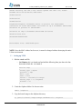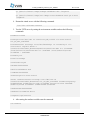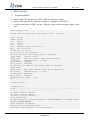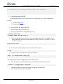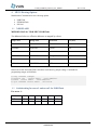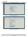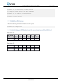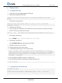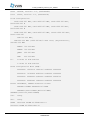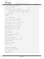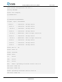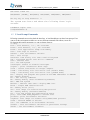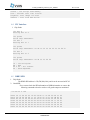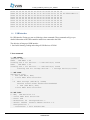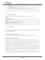
1
DT4CS-Scale out User Manual Guide Revision: A1 © 2015 VVDN Technologies All Rights Reserved VVDN_T4MFCS_Scaleout_User_Manual Rev. A1 Copyright Notice This document is copyright of VVDN, All Rights Reserved. No part of this document, in whole or in part, may be used, reproduced, stored in a retrieval system or transmitted, in any form, or by any means, electronic or otherwise, including photocopying, reprinting, or recording, for any purpose, without the express written permission of VVDN. Legal Disclaimer The information contained in this document is subject to change without notice. The information in this document is provided for informational purposes only. VVDN Technologies specifically disclaims all warranties, express or limited, including, but not limited, to the implied warranties of merchantability and fitness for a particular purpose, except as provided for in a separate software license agreement. The Open Server The Open server provides an established framework to demonstrate the accelrated communication process.It provide the solution for communication with higher network connectivity and powerful security using encryption methodology.It offering powerful unified communication using scale-out and storage option. The storage appliance is designed to provide features that include data compression, deduplication and encryption. VVDN Technologies VVDN Technologies Pvt Ltd is responsible for the design and development of all products . VVDN provide end-to-end product design capability to its customer. Founded in 2007, VVDN is a technology innovation and development company providing a broad spectrum of services and technology expertise to our core domains. VVDN provides “Concept to Customer” services at any point in the development cycle, as well as full turnkey solutions. Correspondence VVDN Technologies, B-22, infocity sector- 34, Gurgaon- 122001, Haryana, India. Email: [email protected] Website: www.theopenservers.com CONFIDENTIAL 2 VVDN_T4MFCS_Scaleout_User_Manual Rev. A1 Revision History: Date Rev No. Description 13-March-2015 A0-01 User Manual -Initial Draft VVDN 23-March-2015 A0-02 Updated BMC GUI Features VVDN 27-March-2015 A0-03 Updated NOR booting Steps VVDN CONFIDENTIAL By 3 VVDN_T4MFCS_Scaleout_User_Manual Rev. A1 Table of contents 1 INTRODUCTION ............................................................................................................................................ 6 2 OVERVIEW .................................................................................................................................................... 6 2.1 PREREQUISITES ....................................................................................................................................................6 2.1.1 Host requirement ...................................................................................................................................6 2.1.2 Target requirements ..............................................................................................................................7 2.2 CONFIGURING THE NETWORK INTERFACE ..................................................................................................................8 2.2.1 Finding and Changing the MAC Address ................................................................................................8 2.3 SETTING UP TFTP ..............................................................................................................................................10 3 BMC INTERFACE ......................................................................................................................................... 12 3.1 3.2 3.3 3.4 4 PREPARING BOARD: ............................................................................................................................................12 UPGRADING IMAGE ON BMC ...............................................................................................................................13 STEPS TO FLASH THE IMAGE ON BMC .....................................................................................................................13 BMC GUI DESCRIPTION FOR DUAL T4 SERVER: .......................................................................................................14 MFCS BOOTING OPTIONS ........................................................................................................................... 22 4.1 NOR FLASH.....................................................................................................................................................22 4.2 SWITCH SETTING FOR SERVER1 AND SERVER2 FOR NOR FLASH ...................................................................................22 4.3 NOR FLASH.....................................................................................................................................................23 4.4 EEPROM FLASH ..............................................................................................................................................23 4.4.1 Switch setting for server1 and server2 for EEPROM Flash ...................................................................23 5 CONFIGURATION AND COMPILATION ........................................................................................................ 24 5.1 5.2 5.3 5.4 6 STARTUP U-BOOT ....................................................................................................................................... 27 6.1 6.2 6.3 6.4 6.5 6.6 6.7 6.8 7 COMPILE U-BOOT FOR SD CARD ............................................................................................................................24 BUILD LINUX KERNEL AND DEVICE TREE ...................................................................................................................24 BUILD ROOT FILE SYSTEM ....................................................................................................................................26 SWITCH SETTING ON T4240MFCS BOARD FOR SERVER1 AND SERVER2 FOR SD CARD ......................................................26 PROGRAM SD CARD ...........................................................................................................................................27 STARTUP U-BOOT FROM SD CARD .........................................................................................................................27 U-BOOT PROMPT COMMANDS: ............................................................................................................................31 I2C INTERFACE ..................................................................................................................................................32 DDR3 SPD.......................................................................................................................................................32 USB INTERFACE .................................................................................................................................................33 SD CARD INTERFACE ...........................................................................................................................................34 PCIE INTERFACE .................................................................................................................................................34 STARTING LINUX FROM SD CARD ............................................................................................................... 36 7.1 7.2 7.3 STEPS FOR ETHERNET PORT SETTING.......................................................................................................................36 UPGRADE U-BOOT ON SD CARD ............................................................................................................................36 UPGRADE UIMAGE AND T4240MFCS.DTB ON SD CARD .............................................................................................37 CONFIDENTIAL 4 VVDN_T4MFCS_Scaleout_User_Manual Rev. A1 Table of figures Figure 1 Login screen ...................................................................................................................................................14 Figure 2 System Page 1 ................................................................................................................................................15 Figure 3 System Page 2 ................................................................................................................................................15 Figure 4 Network Configuration ..................................................................................................................................16 Figure 5 Debug Screen with prompt box to save the logs ...........................................................................................17 Figure 6 Debug Screen .................................................................................................................................................17 Figure 7 T4 Server: Product Details .............................................................................................................................18 Figure 8 Board Details..................................................................................................................................................18 Figure 9 Firmware Upgrade .........................................................................................................................................19 Figure 10 Fan Monitoring ............................................................................................................................................19 Figure 11 Temperature Monitoring .............................................................................................................................20 Figure 12 Voltage Monitoring ......................................................................................................................................20 Figure 13 Power on/off and reset ................................................................................................................................21 Figure 14 Disc Status....................................................................................................................................................21 Figure 15 Configuration for NVME ..............................................................................................................................25 Figure 16 Configuration For RapidIO Support .............................................................................................................25 Figure 17 Table for SD card partition ...........................................................................................................................36 CONFIDENTIAL 5 VVDN_T4MFCS_Scaleout_User_Manual Rev. A0-03 1 Introduction This document will describe in detail the procedures for SDK compilation, booting a Linux kernel and mounting a root file system on the Dual T4240MFCS. The Communication Server product will be built with Dual T4240 which is a communication processor from Freescale. The T4240 QorIQ multicore processor combines 12 dual-threaded e6500 Power Architecture® processor cores for a total of 24 threads with high-performance datapath acceleration logic and network and peripheral bus interfaces required for networking, telecom/datacom, data center, wireless infrastructure, and mil/aerospace applications. A Dual T4240 based Communication server with Scale-out option, offering a powerful unified communication solution with up to 80G of external network connectivity, SRIO inter-chip and external connectivity. External SRIO interface helps to (scale-out) expand system with similar system through Internal SRIO switch. 2 Overview The following files will be released with t4240mfcs. 1. U-boot, linux kernel and root files for T4240mfcs included in the below mentioned binaries: QorIQ-SDK-V1.6-SOURCE-20140619-yocto.iso – ISO to build the SDK. u-boot-with-spl-pbl.bin - U-boot Binary file that could be used to upgrade the U-boot with SD card. u-boot.bin – U-boot binary file that could be used to upgrade the U-boot for NOR Flash. fsl_fman_ucode_t4240_r2.0_106_4_10.bin – fman ucode binary to configure the fman interface. fsl-image-core-t4240mfcs-20150304072707.rootfs.tar.gz - root file system for t4240 mfcs. uImage - Linux kernel for t4240mfcs. t4240mfcs.dtb – linux device tree blob (binaries) for t4240mfcs. 2.1 Prerequisites 2.1.1 Host requirement To properly boot a board host machine must meet the following requirements: 1. Make sure that SDK1.6 is compiled as per the changes required in MFCS project. 2. Modern (latest) GNU/Linux Distribution. a. Ubuntu (Most recent release or LTS) VVDN_T4MFCS_Scaleout_User_Manual Rev. A0-03 3. An internet connection on the Development Host. 4. Root or sudo permission on the Development Host. 5. A copy of the Linux Kernel (uImage) and Root File System (rootfs.tar.gz) for the Target Board that is compiled using SDK 1.6. These are found in the output directory of SDK build, or in the directory build_t4240mfcs_release/tmp/deploy/images/t4240mfcs on the command line. 6. An available serial port on your Development Host. 2.1.2 Target requirements To boot the t4240mfcs board we need the following items: T4240MFCS Board Custom Console cables Ethernet Cable ScaleOut Add On card Once we have all the above mentioned components proceed with the following steps: 1. Connect the serial console port of the board to the serial port of host using the custom console cables on both server1 and server2. 2. SD cards for booting the images. 3. Connect the power supply to the board. 2.1.2.1 Preparing the Target 1. Start minicom on your host machine in configuration mode. As root: # sudo minicom -s -w 2. A menu of configuration should appear. Select the Serial port setup option, and press Enter. 3. Verify that the listed serial port is the same one that is connected to the target board. If it is not, press A, and enter the correct device. This is /dev/ttyS0 on most Linux distributions. 4. Set the Bps/Par/Bits option by pressing the letter E and using the next menu to set the appropriate values. You press the key that corresponds to the value 115200, and then press Enter. 5. Set Hardware flow control to No using the F key. 6. Set Software flow control to No using the G key. 7. Press Enter to return to the main configuration menu, and then press Esc to exit this menu. 8. Reset the board, and wait for a moment. If you do not see output from the board, press Enter several times until you see the prompt. If you do not see any output from the board, and have verified that the serial terminal connection is setup correctly, contact your board vendor. 7 CONFIDENTIAL VVDN_T4MFCS_Scaleout_User_Manual Rev. A0-03 2.2 Configuring the Network Interface 2.2.1 Finding and Changing the MAC Address The MAC address on the T4240MFCS is set by the ethaddr environment variable in U-Boot. If ethaddr is not set, it can be set using the setenv command. Example setenv ethaddr 00:11:22:33:44:55 The MAC Address can be found using the printenv command in U-Boot. Example printenv baudrate=115200 bootargs=root=/dev/ram rw console=ttyS0, 115200 rio-scan.scan=0 fsl_fm_max_frm=9600 bootcmd=setenv bootargs root=/dev/mmcblk0p1 rw rootdelay=5 rioscan.scan=1 rapidio.hdid=-1 console=$consoledev,$baudrate;mmcinfo;ext2load mmc 0:1 $loadaddr /boot/$bootfile;ext2load mmc 0:1 $fdtaddr /boot/$fdtfile;bootm $loadaddr - $fdtaddr bootdelay=10 bootfile=uImage consoledev=ttyS0 eth10addr=00:10:F3:3A: BA:B0 eth11addr=00:10:F3:3A:BA:B1 eth12addr=00:10:F3:3A:BA:B2 eth13addr=00:10:F3:3A:BA:B3 eth14addr=00:10:F3:3A:BA:B4 eth15addr=00:10:F3:3A:BA:BC eth1addr=00:10:F3:3A:BA:AB eth2addr=00:10:F3:3A:BA:AC eth3addr=00:10:F3:3A:BA:A1 eth4addr=00:10:F3:3A:BA:A0 eth5addr=00:10:F3:3A:BA:BF 8 CONFIDENTIAL VVDN_T4MFCS_Scaleout_User_Manual Rev. A0-03 eth6addr=00:10:F3:3A:BA:B8 eth7addr=00:10:F3:3A:BA:B9 eth8addr=00:10:F3:3A:BA:AA ethact=FM1@DTSEC1 ethaddr=00:11:22:33:44:55 ethprime=FM1@DTSEC1 fdtaddr=0x00c00000 fdtfile=t4240mfcs.dtb fman_ucode=7fb6b948 hwconfig=fsl_ddr:ctlr_intlv=3way_4KB,bank_intlv=auto;usb1:dr_mode=host ,phy_type=utmi ipaddr=192.168.1.10 loadaddr=0x1000000 mdioreg1=mdio write FM1@DTSEC1 22 0x12 mdioreg2=mdio write FM1@DTSEC1 20 0x8001 mmcboot=setenv bootargs root=/dev/mmcblk0p1 rwrootdelay=5 console=$consoledev,$baudratefsl_fm_max_frm=9600 ;mmcinfo;ext2load mmc 0:1 $loadaddr /boot/$bootfile;ext2load mmc 0:1 $fdtaddr /boot/$fdtfile;bootm $loadaddr - $fdtaddr netdev=eth0 nfsboot=setenv bootargs root=/dev/nfs rw nfsroot=$serverip:$rootpath ip=$ipaddr:$serverip:$gatewayip:$netmask:$hostname:$netdev:off console=$consoledev,$baudrate $othbootargs;tftp $loadaddr $bootfile;tftp $fdtaddr $fdtfile;bootm $loadaddr - $fdtaddr othbootargs=rio-scan.scan=0 ramboot=setenv bootargs root=/dev/ram rw console=$consoledev,$baudrate fsl_fm_max_frm=9600 $othbootargs;tftp $ramdiskaddr $ramdiskfile;tftp $loadaddr $bootfile;tftp $fdtaddr $fdtfile;bootm $loadaddr $ramdiskaddr $fdtaddr ramdiskaddr=0x02000000 ramdiskfile=ramdisk.uboot rootpath=/opt/nfsroot serverip=192.168.1.251 9 CONFIDENTIAL VVDN_T4MFCS_Scaleout_User_Manual Rev. A0-03 setenv serverip 192.168.1.251; setenv ipaddr 192.168.1.10; setenv ethaddr 00:11:22:33:44:55; bdev=sda3 stderr=serial stdin=serial stdout=serial tftpflash=tftpboot $loadaddr $uboot && protect off $ubootaddr +$filesize && erase $ubootaddr +$filesize && cp.b $loadaddr $ubootaddr $filesize && protect on $ubootaddr+ $filesize && cmp.b $loadaddr $ubootaddr $filesize uboot="u-boot.bin" ubootaddr=0x00201000 Environment size: 2458/8188 bytes NOTE: Once the MAC address has been set, it cannot be changed without destroying the entire U-Boot environment. 2.3 Setting up TFTP 1. Edit the xinetd.conf file o On Ubuntu, edit /etc/xinetd.conf and add the following lines just above the line that reads include dir /etc/xinetd.d. service tftp { socket_type = dgram protocol = udp wait = yes user = root server = /usr/sbin/in.tftpd server_args = -s /tftpboot disable = no } 2. Create the /tftpboot folder if it does not exist: mkdir /tftpboot 3. Copy the kernel image to the /tftpboot directory: cp /path/to/kernel/image/uImage-t4240mfcs.bin /tftpboot 10 CONFIDENTIAL VVDN_T4MFCS_Scaleout_User_Manual Rev. A0-03 cp /path/to/kernel/image/uImage-t4240mfcs.dtb /tftpboot cp /path/to/kernel/image/fsl-image-core-t4240mfcs.ext2.gz.u-boot /tftpboot 4. Restart the xinetd server with the following command: /etc/init.d/xinetd restart 5. Test the TFTP server by setting the environment variables and run the following commands. baudrate=115200 bootargs=root=/dev/ram rw console=ttyS0,115200 rio-scan.scan=0 fsl_fm_max_frm=9600 bootcmd=setenv bootargs root=/dev/mmcblk0p1 rw rootdelay=5 rioscan.scan=1 rapidio.hdid=-1 console=$consoledev,$baudrate;mmcinfo;ext2load mmc 0:1 $loadaddr /boot/$bootfile;ext2load mmc 0:1 $fdtaddr /boot/$fdtfile;bootm $loadaddr - $fdtaddr bootdelay=10 bootfile=uImage consoledev=ttyS0 fdtaddr=0x00c00000 fdtfile=t4240mfcs.dtb loadaddr=0x1000000 othbootargs=rio-scan.scan=0 setenv ramboot=setenv bootargs root=/dev/ram rw console=$consoledev,$baudrate fsl_fm_max_frm=9600 $othbootargs;tftp $ramdiskaddr $ramdiskfile;tftp $loadaddr $bootfile;tftp $fdtaddr $fdtfile;bootm $loadaddr $ramdiskaddr $fdtaddr ramdiskaddr=0x02000000 ramdiskfile=ramdisk.uboot rootpath=/opt/nfsroot 6. After setting the ramboot variables run the command. run ramboot 11 CONFIDENTIAL VVDN_T4MFCS_Scaleout_User_Manual 3 Rev. A0-03 BMC Interface 3.1 Preparing Board: 1. Attach an RS-232 cable between T4240 UART port and host computer. 2. Open a serial console tool on the host computer to communicate with MFCS. 3. Push the reset button for BMC and the following u-boot console messages appear on the host : BMC booting Logs: U-Boot 2009.01.ast(v0.62)-svn39 (Feb 07 2015 - 13:29:07) I2C: ready DRAM: 64 MB In: serial Out: serial Err: serial H/W: AST2400 series chip Rev. 01 Net: eth_initialize faradaynic_initialize Hit any key to stop autoboot: 0 ## Booting kernel from Legacy Image at 20080000 ... Image Name: Linux-2.6.28.9 Image Type: ARM Linux Kernel Image (uncompressed) Data Size: 1842824 Bytes = 1.8 MB Load Address: 40008000 Entry Point: 40008000 ## Loading init Ramdisk from Legacy Image at 20300000 ... Image Name: Image Type: ARM Linux RAMDisk Image (gzip compressed) Data Size: 3894038 Bytes = 3.7 MB Load Address: 40800000 Entry Point: 40800000 Loading Kernel Image ... OK OK Starting kernel ... Uncompressing Linux................................................................. .................................................. sh: UHCI: unknown operand sh: UHCI: unknown operand Starting T4 initialization... Power sequencing... T4-power-sequence t4-power-sequence.0: ############# ALL POWERS FOR T4 ARE UP ############## power sequence successful Releasing Clock Generator Reset... Starting clock generation for T4 processor... 12 CONFIDENTIAL VVDN_T4MFCS_Scaleout_User_Manual Rev. A0-03 Clock generator is configured Starting T4 reset sequences ... 3.2 Upgrading image on BMC To get the images from server it is necessary to configure the server. This configuration involves Create the tftp server. Network configuration. 3.3 Steps to flash the image on BMC 1. Boot the BMC and let the kernel up. 2. Set the ip of the BMC by using ifconfig. For e.g. ifconfig eth0 down ifconfig eth0 192.168.0.45 up 3. Check whether the host is connected or not using ping command. To use tftp, host (e.g. laptop) and BMC should be in same domain. (NOTE: Both server and BMC in same i.e. 192.168.0.x domain) Ping 192.168.0.81 4. If connection is done goto tmp directory. This can be done by cd /tmp 5. Get the image from host by executing tftp command tftp -gr <image name> <host_ip> The image should present in /tftpboot directory in host system. 6. Flash the image to onboard flash memory with the help of following command flashcp -v <image_name> /dev/mtd0 Flashing will take some time for erasing, writing and verifying data. 7. Once the flash is done reboot the BMC. 13 CONFIDENTIAL VVDN_T4MFCS_Scaleout_User_Manual Rev. A0-03 3.4 BMC GUI Description for Dual T4 Server: 1. Connect BMC console. 2. Let BMC and kernel up. Default ip is 192.168.0.45. We can change the default ip by ifconfig eth0 <ip> up. ifconfig eth0 down ifconfig eth0 192.168.0.45 up 3. Now the server starts and opens the URL with the local host ip. 4. And the login page appears on the browser. Figure 1 Login screen 5. Enter the user name and password. Username : admin Password : admin 14 CONFIDENTIAL VVDN_T4MFCS_Scaleout_User_Manual Rev. A0-03 6. On successful login system page will appear on the screen. Figure 2 System Page 1 Figure 3 System Page 2 15 CONFIDENTIAL VVDN_T4MFCS_Scaleout_User_Manual Rev. A0-03 7. System page displays details of server and BMC like serial number, CPU location, BMC FW build time, CPU FW build time, software version of BMC & CPU etc, it displays status of voltage, temperature and power supply unit status. 8. Network Configuration for 1G and 10G ports: Displays the Mac address. IP, Subnet Mask, Gateway of the particular port. There is option to choose static and dynamic. If static, the MAC, IP, Subnet mask and gateway will be default. If dynamic, one can change it and click on apply to apply the changes. Figure 4 Network Configuration 9. Debug console on BMC: Display the location led status (ON/OFF/Blink). Displays the console logs of BMC and Server. The server and BMC logs can be saved as text file. To save the logs click on ON button one prompt will be displayed just click on save. 16 CONFIDENTIAL VVDN_T4MFCS_Scaleout_User_Manual Rev. A0-03 Figure 5 Debug Screen with prompt box to save the logs Figure 6 Debug Screen 17 CONFIDENTIAL VVDN_T4MFCS_Scaleout_User_Manual Rev. A0-03 Figure 7 T4 Server: Product Details Figure 8 Board Details 10. Firmware Upgrade: For upgrading BMC and RCW select the file and the loading symbol it will show. Upgrading will take some time. 18 CONFIDENTIAL VVDN_T4MFCS_Scaleout_User_Manual Rev. A0-03 Figure 9 Firmware Upgrade 11. Fan, Voltage and temperature Monitoring for checking the BMC status Fan page has details of RPM & also status of RPM is within the specified range. Temperature page displays the server temperature, inlet temperature& outlet temperature and also displays the status as OK if it is within the range & fault if it exceeds range. Voltage will display all the current values. Figure 10 Fan Monitoring 19 CONFIDENTIAL VVDN_T4MFCS_Scaleout_User_Manual Rev. A0-03 Figure 11 Temperature Monitoring Figure 12 Voltage Monitoring 20 CONFIDENTIAL VVDN_T4MFCS_Scaleout_User_Manual Rev. A0-03 12. Power Control Mode: For power enabling or reset on server there is server power control showing on the GUI screen and for BMC reset there is a reset control button on BMC Power Control. Figure 13 Power on/off and reset 13. Disc Management utility: For showing the disc utility on server. Figure 14 Disc Status 21 CONFIDENTIAL VVDN_T4MFCS_Scaleout_User_Manual 4 Rev. A0-03 MFCS Booting Options Multifunction Communication server booting options NOR Flash EEPROM Flash SD Card 4.1 NOR FLASH MEMORY MAP for T4240 MFCS NOR Flash: The addresses below are effective addresses as mapped by u-boot. Range Start Range End Definition Size(KB) EC000000 EC01FFFF RCW 112 EFF40000 EFFFFFFF U-Boot 768 EFF00000 EFF1FFFF FMAN 3167 EC020000 EC7FFFFF uImage 5093 ED300000 EFDFFFFF Rootfs 32368 EC800000 ED2FFFFF DTB 629 Board can be boot from NOR Flash. Selections can be done by jumper settings. Commands for programming images in NOR flash: # # # # tftp 1000000 <Image> protect off <start addr> <end address> erase <start addr> <end address> cp.b 1000000 <start addr> $filesize 4.2 Switch setting for server1 and server2 for NOR Flash For server 1: DIP Switch 7 SW7 Off SW8 Off 8 Off Off 9 Off Off 10 Off On 11 Off Off 12 Off On 22 CONFIDENTIAL VVDN_T4MFCS_Scaleout_User_Manual Rev. A0-03 For server 2: DIP Switch 7 SW5 Off SW6 Off 8 Off Off 9 Off Off 10 Off On 11 Off Off 12 Off On 4.3 NOR FLASH When SD Card is used as a booting device NOR Flash can be tested at u-boot prompt with following commands. NOR Flash is the primary booting option which contains RCW,U-boot,U-boot env, fman code etc To read nor flash cp {source address} {target address} {count} To write nor flash mw {source address} {target address or data to be written} {count} To erase NOR Flash Erase {start address} {end address} 4.4 EEPROM FLASH 4.4.1 Switch setting for server1 and server2 for EEPROM Flash For server 1: DIP Switch 7 SW7 Off SW8 Off 8 Off On 9 Off On 10 Off Off 11 Off On 12 Off Off 8 Off On 9 Off On 10 Off Off 11 Off On 12 Off Off For server 2: DIP Switch 7 SW5 Off SW6 Off 23 CONFIDENTIAL VVDN_T4MFCS_Scaleout_User_Manual 5 Rev. A0-03 Configuration and compilation 5.1 Compile u-boot for SD card 1. Goto SDK 1.6 and run the command on the following path: home/root/sdk-path/build_t4240mfcs_release/tmp/work/t4240mfcs-fsllinux/u-boot/2014.01+fslgit-r0/git make ARCH=powerpc CROSS_COMPILE =/home/root/sdk-path/ build_t4240mfcs_release/tmp/sysroots/x86_64-linux/usr /bin/ppce6500fsl-linux/powerpc-fsl-linux- T4240MFCS_SDCARD 2. If build is successful then for u-boot binary image goto the path: In home/root/sdk-path/build_t4240mfcs_release/tmp/work/t4240mfcs-fsllinux/u-boot/2014.01+fslgit-r0/git we will get the following binary on the above mentioned path: u-boot-with-spl-pbl.bin 5.2 Build Linux Kernel and device tree Configure the Linux kernel with default setting: 1. Run the config command on Linux kernel. Enable the following for NVME and Rapid IO support in device by following command: 24 CONFIDENTIAL VVDN_T4MFCS_Scaleout_User_Manual Rev. A0-03 Figure 15 Configuration for NVME Figure 16 Configuration For RapidIO Support 25 CONFIDENTIAL VVDN_T4MFCS_Scaleout_User_Manual Rev. A0-03 bitbake -f -c menuconfig virtual/kernel To compile Linux kernel run the command: bitbake -f -c compile virtual/kernel bitbake virtual/kernel 5.3 Build Root File System 1. Run the following command to build the root file system: bitbake fsl-image-core 5.4 Switch Setting on T4240mfcs board for server1 and server2 for SD Card For server 1: DIP Switch 1 SW7 Off SW8 Off 2 Off On 3 Off On 4 Off On 5 Off On 6 Off On 2 Off On 3 Off On 4 Off On 5 Off On 6 Off On For server 2: DIP Switch 1 SW5 Off SW6 Off 26 CONFIDENTIAL VVDN_T4MFCS_Scaleout_User_Manual 6 Rev. A0-03 Startup u-boot 6.1 Program SD Card 1. Create one ext2 (/dev/sdb1) partition in SD card. 2. Flash u-boot image into SD Card. sudo dd if=u-boot-with-spl-pbl.bin of=/dev/sdb seek=8 count=1560 bs=512 3. Flash fman code into SD card sudo dd if=fsl_fman_ucode_t4240_r2.0_106_4_10.bin of=/dev/sdb seek=3000 bs=512 4. Flash rootfs into SD card 5. Copy fsl-image-core-t4240rdb-20141031084308.rootfs.tar.gz into SD card partition (/dev/sdb1) 6. Extract rootfs by using following command sudo tar –xvf fsl-image-core-t4240rdb-20141031084308.rootfs.tar.gz 7. Flash uImage into SD card Copy uImage into /boot directory of rootfs 8. Flash dtb file into SD card Copy t4240mfcs.dtb into /boot directory of rootfs 9. Plug SD card into mmc slot of board 10. Boot the board and catch u-boot prompt 11. Command line parameter to be set at u-boot prompt setenv bootcmd 'setenv bootargs root=/dev/mmcblk0p1 rw rootdelay=5 console=$consoledev, $baudrate; mmcinfo; ext2load mmc 0:1 $loadaddr /boot/$bootfile; ext2load mmc 0:1 $fdtaddr /boot/$fdtfile; bootm $loadaddr - $fdtaddr' 12. Set environment variables on Server 1 and Server 2. 13. Run following command to load uImage ,t4240mfcs.dtb and rootfs # run bootcmd 6.2 Startup u-boot from SD card T4240MFCS SD BOOT U-Boot 2014.01QorIQ-SDK-V1.6+gfe1d4f5 (May 27 2015 - 14:18:15) 27 CONFIDENTIAL VVDN_T4MFCS_Scaleout_User_Manual CPU0: T4240E, Version: 2.0, (0x82480020) Core: e6500, Version: 2.0, (0x80400120) Rev. A0-03 Clock Configuration: CPU0:1666.667 MHz, CPU1:1666.667 MHz, CPU2:1666.667 MHz, CPU3:1666.667 M CPU4:1666.667 MHz, CPU5:1666.667 MHz, CPU6:1666.667 MHz, CPU7:1666.667 M CPU8:1666.667 MHz, CPU9:1666.667 MHz, CPU10:1666.667 MHz, CPU11:1666.667 CCB:733.333 MHz, DDR:933.333 MHz (1866.667 MT/s data rate) (Asynchronous), IFC:183.333 MHz FMAN1: 733.333 MHz FMAN2: 733.333 MHz L1: QMAN: 366.667 MHz PME: 533.333 MHz D-cache 32 KiB enabled I-cache 32 KiB enabled Reset Configuration Word (RCW): 00000000: 16070019 18101916 00000000 00000000 00000010: 70702828 40555200 0c020000 f5000000 00000020: 00000000 ee0000ee 00000000 000287fe 00000030: 00000440 10000009 00000000 00000028 Board: T4240MFCS, SERDES Reference Clocks: SERDES1=100MHz SERDES2=156.25MHz SERDES3=(PLL1=125MHz,PLL2=156.2MHz) SERDES4=(PLL1=125,PLL2=100MHz) I2C: ready SPI: ready DRAM: Detected UDIMM D3-66JK118SV-13 Detected UDIMM D3-66JK118SV-13 28 CONFIDENTIAL VVDN_T4MFCS_Scaleout_User_Manual Rev. A0-03 Detected UDIMM D3-66JK118SV-13 10 GiB left unmapped 12 GiB (DDR3, 64-bit, CL=13, ECC on) DDR Controller Interleaving Mode: 3-way 4KB DDR Chip-Select Interleaving Mode: CS0+CS1 Flash: Flash_Init 128 MiB L2: 2 MiB enabled enable l2 for cluster 1 fec60000 enable l2 for cluster 2 feca0000 Corenet Platform Cache: 1.5 MiB enabled Using SERDES1 Protocol: 28 (0x1c) Using SERDES2 Protocol: 56 (0x38) Using SERDES3 Protocol: 5 (0x5) Using SERDES4 Protocol: 5 (0x5) SRIO1: enabled SRIO2: enabled EC1 FM2 DTSEC5NAND: MMC: 0 MiB FSL_SDHC: 0 Backplane Configuration Check SerDes Configuration for PCIe 1 Setting LAW BAR PCIe1: Root Complex, @@ LTSSM1=0x00. @@ 0xfe240f14=0x90000000. no link, regs @ 0xfe240000 PCIe1: Bus 00 - 00 PCIe1: busno 1 29 CONFIDENTIAL VVDN_T4MFCS_Scaleout_User_Manual Rev. A0-03 Check SerDes Configuration for PCIe 3 Setting LAW BAR PCIe3: Root Complex, @@ LTSSM1=0x11. @@ 0xfe240f14=0x90000000. x4 gen2, regs @ 0xfe260000 02:00.0 03:01.0 04:00.0 03:02.0 05:00.0 03:03.0 06:00.0 - 10b5:8724 - Bridge device - 10b5:8724 - Bridge device - 10b5:87b0 - Bridge device - 10b5:8724 - Bridge device - 8086:0953 - Mass storage controller - 10b5:8724 - Bridge device - 8086:0953 - Mass storage controller 03:08.0 - 10b5:8724 - Bridge device 03:09.0 - 10b5:8724 - Bridge device 03:0a.0 - 10b5:8724 - Bridge device PCIe3: Bus 01 - 09 PCIe3: busno 10 PCIe4: disabled PCIe4: busno In: serial Out: serial Err: serial Net: Fman1: Uploading microcode version 106.4.14 PHY reset timed out PHY reset timed out Fman2: Uploading microcode version 106.4.14 PHY reset timed out 30 CONFIDENTIAL VVDN_T4MFCS_Scaleout_User_Manual Rev. A0-03 PHY reset timed out FM1@DTSEC1 [PRIME], FM1@TGEC1, FM1@TGEC2, FM2@TGEC1, FM2@TGEC2 Hit any key to stop autoboot: 0 The system auto boots and shows the following Linux login screens. t4240mfcs login: root root@t4240mfcs:~# 6.3 U-boot Prompt Commands: Following commands are used to check the interfaces or load the addresses on the u-boot prompt. If we want to set the environment variables we can use different commands like editenv, setenv etc. For booting the kernel from memory we can use bootm, boot etc. => help boot - boot default, i.e., run 'bootcmd' bootd - boot default, i.e., run 'bootcmd' bootm - boot application image from memory echo - echo args to console editenv - edit environment variable exit - exit script ext2load- load binary file from a Ext2 filesystem fdt - flattened device tree utility commands func - execute func i2c - I2C sub-system interrupts- enable or disable interrupts Irqinfo - print information about IRQs itest - return true/false on integer compare loadb - load binary file over serial line (kermit mode) loady - load binary file over serial line (ymodem mode) mac - display and program the system ID and MAC addresses in EEPROM md - memory display mii - MII utility commands mm - memory modify (auto-incrementing address) mmc - MMC sub system mmcinfo - mmcinfo <dev num>-- display MMC info mtest - simple RAM read/write test mw - memory write (fill) nfs - boot image via network using NFS protocol nm - memory modify (constant address) pci - list and access PCI Configuration Space ping - send ICMP ECHO_REQUEST to network host printenv- print environment variables rarpboot- boot image via network using RARP/TFTP protocol reset - Perform RESET of the CPU run - run commands in an environment variable saveenv - save environment variables to persistent storage setenv - set environment variables 31 CONFIDENTIAL VVDN_T4MFCS_Scaleout_User_Manual Rev. A0-03 source - run script from memory test - minimal test like /bin/sh tftpboot- boot image via netw usbboot - boot from USB device 6.4 I2C Interface 1. Chip Probe i2c dev 0 Setting bus to 0 i2c probe Valid chip addresses: i2c dev 1 Setting bus to 1 i2c probe Valid chip addresses: 1A 1B 1C 32 33 34 52 53 54 68 70 i2c dev 2 Setting bus to 2 i2c probe Valid chip addresses: 1B 24 33 53 60 62 70 68 60 24 – – & – I2c multiplex RTC 62 – PCI retimer GPIO Expander 6.5 DDR3 SPD 1. Chip Probe: The DDR3 SPD address is 52h,53h,54h (8-bit), and it can be accessed at I2C#2. 2. Read SPD If we want to check the SPD information or DDR information we can use the following command to check or read we will get the output as mentioned: i2c md 52 0 100 0000: 0010: 0020: 0030: 0040: 0050: 0060: 92 69 80 00 00 00 00 13 78 00 00 00 00 00 0b 69 ca 00 00 00 00 02 28 00 00 00 00 00 03 69 00 00 00 00 00 19 11 00 00 00 00 00 00 10 00 00 00 00 00 09 79 00 00 00 00 00 0b 00 00 00 00 00 00 11 05 00 00 00 00 00 01 3c 00 00 00 00 00 08 3c 00 00 00 00 00 09 00 00 04 00 00 00 00 d8 00 11 00 00 00 fc 83 00 29 00 00 00 02 01 00 01 00 00 00 32 CONFIDENTIAL VVDN_T4MFCS_Scaleout_User_Manual 0070: 0080: 0090: 00a0: 00b0: 00c0: 00d0: 00e0: 00f0: 00 44 00 00 00 00 00 00 00 00 33 00 00 00 00 00 00 00 00 2d 00 00 00 00 00 00 00 00 36 00 00 00 00 00 00 00 00 36 80 00 00 00 00 00 00 85 4a ce 00 00 00 00 00 00 43 4b 00 00 00 00 00 00 00 00 31 00 00 00 00 00 00 00 0f 31 00 00 00 00 00 00 00 02 38 00 00 00 00 00 00 00 00 53 00 00 00 00 00 00 00 00 56 00 00 00 00 00 00 00 00 2d 00 00 00 00 00 00 00 00 31 00 00 00 00 00 00 00 64 33 00 00 00 00 00 00 00 Rev. A0-03 18 00 D3-66JK118SV-13. 00 00 00 00 00 00 00 6.6 USB Interface For USB Interface Testing you can use following u-boot commands. These commands will give you detailed information of the USB controller and devices connected to the USB. The objective of bring up of USB interface 1. Successful Scanning, reading and writing all USB Devices of T4240 U-boot commands => usb reset (Re)start USB... USB0: USB EHCI 1.00 scanning bus 0 for devices... 2 USB Device(s) found USB1: USB EHCI 1.00 scanning bus 1 for devices... 1 USB Device(s) found scanning usb for storage devices... 1 Storage Device(s) found => usb tree USB device tree: 1 Hub (480 Mb/s, 0mA) | u-boot EHCI Host Controller | +-2 Mass Storage (480 Mb/s, 200mA) SanDisk Cruzer Blade 200421032111ADD2A0C5 3 Hub (480 Mb/s, 0mA) u-boot EHCI Host Controller => 1: - usb info Hub, USB Revision 2.0 u-boot EHCI Host Controller Class: Hub PacketSize: 64 Configurations: 1 Vendor: 0x0000 Product 0x0000 Version 1.0 Configuration: 1 - Interfaces: 1 Self Powered 0mA 33 CONFIDENTIAL VVDN_T4MFCS_Scaleout_User_Manual Rev. A0-03 Interface: 0 - Alternate Setting 0, Endpoints: 1 - Class Hub - Endpoint 1 In Interrupt MaxPacket 2048 Interval 255ms 6.7 SD Card Interface U-boot provides the standard command "mmc" to check, read, erase and write SD Card. =>help mmc mmc - MMC sub system Usage: mmc read <device num> addr blk# cnt mmc write <device num> addr blk# cnt mmc rescan <device num> mmc list - lists available devices 6.8 PCIe Interface PCIe Interface Testing can be done from u-boot level. PCI commands will show you the device ids of the devices connected to pci bus. The objective of bring up of PCIe interface 1. Successful Scanning, reading and writing all PCI Devices connected to pci bus of T4240. Following are the u-boot commands pci [bus] [long] - short or long list of PCI devices on bus 'bus' pci header b.d.f - show header of PCI device 'bus.device.function' pci display[.b, .w, .l] b.d.f [address] [# of objects] - display PCI configuration space (CFG) pci next[.b, .w, .l] b.d.f address - modify, read and keep CFG address pci modify[.b, .w, .l] b.d.f address address - modify, auto increment CFG pci write[.b, .w, .l] b.d.f address value - write to CFG address 34 CONFIDENTIAL VVDN_T4MFCS_Scaleout_User_Manual Rev. A0-03 Examples: => pci 0 Scanning PCI devices on bus 0 BusDevFun VendorId DeviceId Device Class Sub-Class _____________________________________________________________ 00.00.00 0x1957 0x0440 Processor 0x20 => pci 1 Scanning PCI devices on bus 1 BusDevFun VendorId DeviceId Device Class Sub-Class _____________________________________________________________ 01.00.00 0x1957 0x0800 Processor 0x2 => pci display 0 00000000: 04401957 00000010: df000000 00000020: e010e000 00000030: 00000000 00100006 00000000 00011001 00000040 0b200010 00010100 00000000 00000000 00810008 00000111 00000000 000001ff From the linux terminal we can scan pci devices and read write memory and I/O Space allocated to it using SYSFS and lspci. => lspci 00:00.0 Host bridge: Intel Corporation Haswell-ULT DRAM Controller (rev 0b) 00:14.0 USB controller: Intel Corporation Lynx Point-LP USB xHCI HC (rev 04) 00:1c.0 PCI bridge: Intel Corporation Lynx Point-LP PCI Express Root Port 1 (rev e4) 00:1c.2 PCI bridge: Intel Corporation Lynx Point-LP PCI Express Root Port 3 (rev e4) 00:1c.3 PCI bridge: Intel Corporation Lynx Point-LP PCI Express Root Port 4 (rev e4) 00:1c.4 PCI bridge: Intel Corporation Lynx Point-LP PCI Express Root Port 5 (rev e4) 00:1d.0 USB controller: Intel Corporation Lynx Point-LP USB EHCI #1 (rev 04) 00:1f.2 SATA controller: Intel Corporation Lynx Point-LP SATA Controller 1 [AHCI mode] (rev 04) 35 CONFIDENTIAL VVDN_T4MFCS_Scaleout_User_Manual 7 Rev. A0-03 Starting Linux from SD Card The Linux kernel and file system can be copied to the SD card for production deployment. As such the SD card included in the t4240mfcs kit will contain the different images for linux kernel, root filesystem and the device tree binaries in the /dev/sdb partition as mentioned in the figure. Figure 17 Table for SD card partition 7.1 Steps for Ethernet port setting a. Connect Ethernet cable between server1/server2, where need to upgrade images and Linux PC b. Ethernet port setting required at server1/server2 for upgrading the images in SD card, Catch kernel prompt and run following command sudo ifconfig fm1-mac1 192.168.1.10 up c. Ethernet port setting at Linux PC side sudo ifconfig eth0 192.168.1.20 up 7.2 Upgrade u-boot on SD card a. Go to the directory where “ u-boot-with-spl-pbl.bin” file is present in Linux PC b. Copy image into SD card by using scp scp u-boot-with-spl-pbl.bin [email protected]: Now Copy this binary into /dev/mmcblk0 partition of SD card 36 CONFIDENTIAL VVDN_T4MFCS_Scaleout_User_Manual Rev. A0-03 sudo dd if=u-boot-with-spl-pbl.bin of=/dev/mmcblk0 seek=8 count=1560 bs=512 c. Reboot the board 7.3 Upgrade uImage and t4240mfcs.dtb on SD card a. Go to the directory where “ uImage and t4240mfcs.dtb” file is present in Linux PC b. Mount directory. mkdir mount mount -t ext2 /dev/mmcblk0p1 mount/ c. Copy image into SD card by using scp scp uImage root@<board ip>:/home/root/mount/boot/ scp t4240mfcs.dtb root@<board ip>:/home/root/mount/boot/ umount /home/root/mount d. Reboot the board. Reboot the Right T4240 Board (Server 1) Press Reset button, for right t4240 reset release reset button when power led is blinking fast (3-6 seconds). Reboot the left T4240 Board (Server 2) Press Reset button, for left t4240 reset release reset button when power led is blinking slow (9-12 seconds). Button 0-3 sec 3-6 sec (Fast blink power led) 6-9 sec 9-12 sec (Slow blink power led) Reset No Action Right T4240 Reset No Action left T4240 Reset 37 CONFIDENTIAL