1
PM-IRRAS Accessory
Hardware Manual
Notices
© Agilent Technologies, Inc. 20102013
No part of this manual may be
reproduced in any form or by any
means (including electronic storage
and retrieval or translation into a
foreign language) without prior
agreement and written consent from
Agilent Technologies, Inc. as governed
by United States and international
copyright laws.
Manual Part Number
8510258800
Edition
Fifth edition, May 2013
Printed in Malaysia
Agilent Technologies, Inc.
Warranty
The material contained in this
document is provided “as is,” and is
subject to being changed, without
notice, in future editions. Further, to
the maximum extent permitted by
applicable law, Agilent disclaims all
warranties, either express or implied,
with regard to this manual and any
information contained herein,
including but not limited to the
implied warranties of merchantability
and fitness for a particular purpose.
Agilent shall not be liable for errors
or for incidental or consequential
damages in connection with the
furnishing, use, or performance of
this document or of any information
contained herein. Should Agilent and
the user have a separate written
agreement with warranty terms
covering the material in this
document that conflict with these
terms, the warranty terms in the
separate agreement shall control.
Technology Licenses
The hardware and/or software
described in this document are
furnished under a license and may be
used or copied only in accordance
with the terms of such license.
Restricted Rights Legend
If software is for use in the
performance of a U.S. Government
prime contract or subcontract,
Software is delivered and licensed as
“Commercial computer software” as
defined in DFAR 252.227-7014 (June
1995), or as a “commercial item” as
defined in FAR 2.101(a) or as
“Restricted computer software” as
defined in FAR 52.227-19 (June 1987)
or any equivalent agency regulation or
2
contract clause. Use, duplication or
disclosure of Software is subject to
Agilent Technologies’ standard
commercial license terms, and nonDOD Departments and Agencies of the
U.S. Government will receive no
greater than Restricted Rights as
defined in FAR 52.227-19(c)(1-2) (June
1987). U.S. Government users will
receive no greater than Limited Rights
as defined in FAR 52.227-14 (June
1987) or DFAR 252.227-7015 (b)(2)
(November 1995), as applicable in any
technical data.
Safety Notices
CAUTION
A CAUTION notice denotes a hazard.
It calls attention to an operating
procedure, practice, or the like that, if
not correctly performed or adhered to,
could result in damage to the product
or loss of important data. Do not
proceed beyond a CAUTION notice
until the indicated conditions are fully
understood and met.
WARNING
A WARNING notice denotes a
hazard. It calls attention to an
operating procedure, practice, or the
like that, if not correctly performed or
adhered to, could result in personal
injury or death. Do not proceed
beyond a WARNING notice until the
indicated conditions are fully
understood and met.
PM-IRRAS Accessory Hardware Manual
Safety Practices and Hazards
Contents
1. Safety Practices and Hazards
5
Cryogenic cooling
5
Electrical hazards
6
Laser safety
6
Other precautions
7
Warnings and cautions
8
Information symbols
8
CE compliance
10
Electromagnetic Compatibility
11
EN55011/CISPR11
ICES/NMB-001
2. Introduction
11
12
13
Specifications
Environmental
Power
Purge gas
Liquid nitrogen
Weights and dimensions
Space
13
13
14
14
15
15
15
Installation requirements
16
Training
16
Documentation
16
PM-IRRAS Accessory Hardware Manual
3
Safety Practices and Hazards
3. Hardware
17
Overview
17
Beam path
18
Filters
19
Orientation of sample and detector
20
4. Basic Operation
21
Introduction
21
Data collection
23
Preparing the PEM-IRRAS
23
Power
Detector cooling
Sample purge
Scanning
4
23
23
24
24
Data Collection in Step Scan Mode
27
Data Collection in Rapid Scan Mode
32
5. Maintenance
35
Cleaning
35
Fuses
36
Spare parts
36
PM-IRRAS Accessory Hardware Manual
Safety Practices and Hazards
1. Safety Practices and Hazards
Cryogenic cooling
Electrical hazards
Laser safety
Other precautions
Warnings and cautions
Information symbols
CE compliance
Electromagnetic Compatibility
5
6
6
7
8
8
10
11
The Polarization Modulation Infrared Reflection Absorption
Spectroscopy (PM-IRRAS) accessory has been carefully designed to
be used as an accessory for Agilent FTIR spectrometers. When used
properly it provides an accurate, fast, flexible and safe analytical
system.
If the equipment is not used in a manner specified by the
manufacturer, the protection provided by the equipment may be
impaired.
Information on safety practices appear throughout the
documentation (both printed and online) provided with your
spectrometer. Before using the PM-IRRAS accessory, you must
thoroughly read these safety practices.
Observe all relevant safety practices at all times.
Cryogenic cooling
Detectors used with your PM-IRRAS accessory are cryogenically
cooled. The liquid nitrogen used in this process is extremely cold and
can cause damage to the human body. Use appropriate protective
equipment when working with liquid nitrogen.
PM-IRRAS Accessory Hardware Manual
5
Safety Practices and Hazards
Electrical hazards
The Agilent PM-IRRAS accessory contains electrical circuits, devices,
and components operating at dangerous voltages. Contact with these
circuits, devices and components can cause death, serious injury, or
painful electrical shock.
Good grounding/earthing is essential to avoid a potentially serious
electric shock hazard. Ensure that there is an integral ground
connection between the metal surfaces of the PM-IRRAS accessory
and the 3 pin earth-grounded receptacle.
NOTE
The above model is Equipment Class I
Application of the wrong supply voltage can create a fire hazard and
a potentially serious shock hazard, and could seriously damage the
PM-IRRAS accessory.
Replace blown fuses with fuses of the size and rating as stipulated in
the text adjacent to the fuse holder or in the manuals where listed.
Do NOT use power cords with faulty or frayed insulation.
Laser safety
The Agilent PM-IRRAS accessory is used with Agilent FTIR
spectrometers, which incorporate a helium-neon (He-Ne) laser
operating in the visible region at 632.8 nanometers. The spectrometer
is a Class 2 laser product, powerful enough to warrant caution in its
use. Agilent FTIR spectrometers comply with FDA and CE standards
for light-emitting products.
6
PM-IRRAS Accessory Hardware Manual
Safety Practices and Hazards
An attenuated portion of the laser beam passes into and through the
spectrometer sample compartment and can be directed from there
into the accessory. Although not powerful enough to harm your skin
should your hand intercept it, the laser light could cause retinal (eye)
damage during prolonged direct viewing. This is not possible given
the normal optical layout of the spectrometer. However, if a highly
reflective surface such as a mirror is allowed to intercept the beam,
the beam could be redirected out of the sample compartment
resulting in on-axis or direct viewing. Care must be taken to avoid
this.
Refer to the spectrometer hardware manual for more information
about the laser.
Other precautions
Use of the PM-IRRAS accessory may involve materials, solvents and
solutions which are flammable, corrosive, toxic or otherwise
hazardous. Careless, improper, or unskilled use of such materials,
solvents and solutions can create explosion hazards, fire hazards,
toxicity and other hazards which can result in death, serious
personal injury, and damage to equipment and property.
ALWAYS ensure that laboratory safety practices governing the use,
handling and disposal of such materials are strictly observed. These
safety practices should include the wearing of appropriate safety
clothing and safety glasses.
PM-IRRAS Accessory Hardware Manual
7
Safety Practices and Hazards
Warnings and cautions
Carefully read all warnings and cautions and observe them at all
times.
A Warning message is used in the text when failure to observe
instructions or precautions could result in death or injury. Warnings
have the following format:
WARNING
Hazard Type
Nature of the hazard, information on how to avoid the hazard, and possible
consequences if you don’t.
The triangular symbols that appear in conjunction with warnings are
outlined in the next section.
A Caution message is used when failure to observe instructions could
result in damage to equipment (Agilent-supplied and/or other
associated equipment). Cautions have the following format:
CAUTION
Caution information appears here.
Information symbols
The following triangular symbols appear in conjunction with
warnings on the spectrometer and associated documentation. The
hazard they depict is shown below each symbol:
8
PM-IRRAS Accessory Hardware Manual
Safety Practices and Hazards
Broken glass
Corrosive liquid
Electrical shock
Extreme cold
Eye hazard
Fire hazard
Heavy weight
(danger to feet)
Heavy weight
(danger to hands)
Hot surface
Laser hazard
Moving parts
Noxious gas
The following symbol may be used on warning labels attached to the
instrument. When you see this symbol, refer to the relevant operation
or service manual for the correct procedure referred to by that
warning label.
PM-IRRAS Accessory Hardware Manual
9
Safety Practices and Hazards
The following symbols also appear on the instrument or in the
documentation:
I
Mains power on.
0
Mains power off.
Fuse.
Single phase alternating current.
When attached to the rear of the instrument, indicates that the product complies with
the requirements of one or more EU directives.
When attached to the rear of the product, indicates that the product has been certified
(evaluated) to CSA 61010.1 and UL 61010-1.
CE compliance
The Agilent Polarization Modulation Infrared Reflection Absorption
Spectroscopy (PM-IRRAS) accessory has been designed to comply
with the requirements of the Electromagnetic Compatibility (EMC)
Directive and the Low Voltage (electrical safety) Directive (commonly
referred to as the LVD) of the European Union. Agilent has
confirmed that each product complies with the relevant directives by
testing a prototype against the prescribed EN (European Norm)
standards.
Proof that a product complies with the directives is indicated by:
10
The CE marking appearing on the rear of the product.
The documentation package that accompanies the product,
containing a copy of the Declaration of Conformity. This
declaration is the legal declaration by Agilent that the product
complies with the directives and also shows the EN standards to
which the product was tested to demonstrate compliance.
PM-IRRAS Accessory Hardware Manual
Safety Practices and Hazards
Electromagnetic Compatibility
EN55011/CISPR11
Group 1 ISM equipment: group 1 contains all ISM equipment in
which there is intentionally generated and/or used conductively
coupled radio- frequency energy which is necessary for the internal
functioning of the equipment itself.
Class A equipment is equipment suitable for use in all
establishments other than domestic and those directly connected to a
low voltage power supply network which supplies buildings used for
domestic purposes.
This device complies with the requirements of CISPR11, Group 1,
Class A as radiation professional equipment. Therefore, there may be
potential difficulties in ensuring electromagnetic compatibility in
other environments, due to conducted as well as radiated
disturbances.
Operation is subject to the following two conditions:
1
This device may not cause harmful interference.
2
This device must accept any interference received, including
interference that may cause undesired operation.
If this equipment does cause harmful interference to radio or
television reception, which can be determined by turning the
equipment off and on, the user is encouraged to try one or more of
the following measures:
1
Relocate the radio or antenna.
2
Move the device away from the radio or television.
3
Plug the device into a different electrical outlet, so that the device
and the radio or television are on separate electrical circuits.
4
Make sure that all peripheral devices are also certified.
PM-IRRAS Accessory Hardware Manual
11
Safety Practices and Hazards
5
Make sure that appropriate cables are used to connect the device
to peripheral equipment.
6
Consult your equipment dealer, Agilent Technologies, or an
experienced technician for assistance.
7
Changes or modifications not expressly approved by Agilent
Technologies could void the user’s authority to operate the
equipment.
ICES/NMB-001
This ISM device complies with Canadian ICES- 001.
Cet appareil ISM est conforme à la norme NMB-001 du Canada.
12
PM-IRRAS Accessory Hardware Manual
Introduction
2. Introduction
Specifications
Environmental
Power
Purge gas
Liquid nitrogen
Weights and dimensions
Space
Installation requirements
Training
Documentation
13
13
14
14
15
15
15
16
16
16
Specifications
Environmental
The Agilent Polarization Modulation Infrared Reflection Absorption
Spectroscopy (PM-IRRAS) accessory is designed for indoor use. It is
suitable for the following categories:
Installation category II
Pollution degree 2
Equipment Class I
These conditions are required for proper operation of your
PM-IRRAS accessory:
Temperature: 20 °C to 26 °C (68 °F to 80 °F)
Temperature gradient: 1 °C/hr (1.8 °F/hr) maximum
Relative humidity: 20% to 50% non-condensing
PM-IRRAS Accessory Hardware Manual
13
Introduction
NOTE
Altitude: 3000 m (10,000 ft) maximum
Free from corrosive and flammable fumes
Free from strong electromagnetic fields
Performance degradation may result from the exposure of the spectrometer to
strong radio frequency energy. If degradation is experienced, reorient or relocate
the spectrometer or the radio frequency source.
Free from vibrations
Power
PEM controller: 60 VA
100 to 240 VAC, 60 W, 50 or 60 Hz. An auto-ranging power supply
is used. No reconfiguration is required for voltage changes.
Dedicated, 10-A circuit with grounded receptacle.
Purge gas
A source of clean, dry air (dried to dew point of —70 °C) or liquid
nitrogen boil-off to be used as a purge gas. Where compressed
nitrogen is used, it must be dry, oil-free and uncontaminated, with
purity of 99.996% or better.
A flow rate of 13 L/min (30 ft3/hr) maximum is required to assure a
non-condensing environment.
The gas supply must be equipped with fittings to accept 6 mm outer
diameter (OD) tubing.
Tubing should be clean and free of any dust and debris. Do not use
tubing treated with talcum powder.
14
PM-IRRAS Accessory Hardware Manual
Introduction
Liquid nitrogen
WARNING
Extreme Cold Hazard
Liquid nitrogen is very cold and can cause damage to the human body. Use
appropriate protective equipment when handling liquid nitrogen.
The detector in the PM-IRRAS accessory will require a supply of
liquid nitrogen to cool it. It takes about 500 milliliters (16 ounces) of
liquid nitrogen for the initial fill to bring the Dewar to an equilibrium
temperature. It will take about 20 minutes to reach equilibrium. Then
add an additional 200 milliliters (7 ounces) of liquid nitrogen to top
off the Dewar.
Weights and dimensions
Width: 67.5 cm (27 in)
Depth: 61 cm (24 in)
Height: 27.5 cm (11 in)
Weight: 45 kg (100 lb)
Space
A flat and level surface is required. It must be rigid enough to
support the weight of the spectrometer and the PM-IRRAS accessory
and any additional accessories (if applicable) without warping or
sagging. The loaded flatness tolerance is 0.4 millimeter per 300
millimeters of length (1/64 inch per foot of length).
A minimum of 30 centimeters (12 inches) of free space is required
behind the spectrometer and PM-IRRAS accessory.
An overhead space of 75 centimeters (30 inches) is required.
PM-IRRAS Accessory Hardware Manual
15
Introduction
Installation requirements
Before receiving your Agilent FTIR spectrometer and PM-IRRAS
accessory, you will have been given a copy of the FTIR spectrometer
Site Preparation Guide, which describes the environmental and
operating requirements of the spectrometer system. You must
prepare your laboratory according to these instructions before the
system can be installed. You should keep the pre-installation manual
for future reference. If you have misplaced your copy, you can obtain
a replacement from your local Agilent office.
Training
The software provided with your Agilent FTIR spectrometer includes
an extensive Help applicable for the spectrometer and the PM-IRRAS
accessory. If you require additional instruction or training, contact
your local Agilent office.
Documentation
This hardware manual provides basic instructions for operating and
maintaining your PM-IRRAS accessory.
In addition to this manual you may receive other hardware and
software manuals depending on the type of configuration purchased.
Further information and instructions about software, analysis
methodology, operating procedures and various accessories is
provided in the Help and electronic manuals saved onto your
computer hard drive during software installation for your Agilent
FTIR spectrometer.
16
PM-IRRAS Accessory Hardware Manual
Hardware
3. Hardware
Overview
Beam path
Filters
Orientation of sample and detector
17
18
19
20
Overview
The Agilent Polarization Modulation Infrared Reflection Absorption
Spectroscopy (PM-IRRAS) accessory is designed to be used as an
accessory for Agilent FTIR spectrometers. The PM-IRRAS accessory
is used for grazing-angle reflectance spectroscopy.
The PM-IRRAS accessory includes:
NOTE
External Experiment Module (EEM) (including Plexiglas cover).
Base plate with optics mounts.
Base plate with one liquid nitrogen-cooled detector.
Photoelastic Modulator (PEM).
PEM controller (complete with user manual).
This hardware manual.
The PEM and the PEM controller are manufactured by Hinds Instruments, Inc.
Details concerning operation and specifications of these devices are not
provided in this manual. Should you require information about these devices
please contact Hinds Instruments, Inc. directly.
PM-IRRAS Accessory Hardware Manual
17
Hardware
The PM-IRRAS accessory is attached to the right side of an Agilent
600 Series FTIR spectrometer. It is installed and aligned by your
Agilent customer service representative.
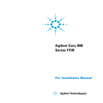
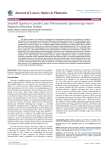
Beam path
The infrared beam exits the spectrometer and is directed by two flat
mirrors (A and C in Figure 1) to the parabolic mirror (D) for
focusing.
J
A
I
H
G
B
F
E
C
D
Figure 1. Agilent PM-IRRAS accessory beam path with cover removed for clarity
A) Flat mirror
B) Beam from spectrometer
C) Flat mirror
D) Parabolic mirror
E) UDR filter
F) Polarizer
G) Photo-elastic modulator H) Angle Indicator
I) Sample
J) Detector
18
PM-IRRAS Accessory Hardware Manual
Hardware
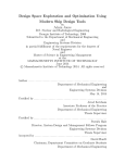
Filters
The focused beam may pass through three optical elements before
passing through the Photoelastic Modulator (PEM). As shown in
figure 2 these elements are:
Infrared polarizer (A in Figure 2): with the plane of polarization
set parallel to the plane of incidence at the sample.
UDR filter (B in Figure 2) location for UDR4 or UDR8 filter: The
UDR filters are optical lowpass filters which transmit below
3,950 cm-1 (UDR4 filter) or 1,975 cm-1 (UDR8 filter), and are used
with the UDR=4 or UDR=8 parameter setting, respectively, of
Resolutions Pro software.
Quartz window (optional, C in Figure 2): acting as a high pass
optical filter transmitting above 2,000 cm-1. When used with the
UDR4 filter (see below), allows data collection at UDR=8 for the
bandpass between 3,950 and 2,000 cm-1. To display data in the
required range click ‘Transforms’ > ‘Fourier Transform’ >
‘Advanced’ and use the ‘Included Frequency’ parameter.
Beam direction
Figure 2. Infrared polarizer plane of polarization
A) Polarizer
B) UDR filter
C) Quartz window
The filters and polarizers must be placed in the order as shown in
Figure 2.
PM-IRRAS Accessory Hardware Manual
19
Hardware
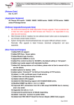
Orientation of sample and detector
Mount the sample (maximum sample size 75 mm) in the optical
clamp so that the clamp grips the edge of the sample. The detector
should be offset from 90° by twice the sample angle. The beam exits
the PEM along the 90° line. Typically, the sample should be set along
the 80° line (10° offset) and the detector set at 70° (20° offset). The
detector position may be optimized by maximizing the magnitude of
the interferogram centerburst in rapid scan setup mode while making
small adjustments of the detector angle. The ZnSe lens assembly has
been optimized on installation. Do not adjust the lens relative to the
detector.
A
B
C
Figure 3. Sample and detector orientation
A) Detector
B) Angle indicator
20
C) Sample
PM-IRRAS Accessory Hardware Manual
Basic Operation
4. Basic Operation
Introduction
Data collection
Preparing the PEM-IRRAS
Data Collection in Step Scan Mode
Data Collection in Rapid Scan Mode
21
23
23
27
32
Introduction
A schematic diagram of a PM-IRRAS experiment is shown in
Figure 4:
Figure 4. Schematic diagram of an IRRAS experiment
PM-IRRAS Accessory Hardware Manual
21
Basic Operation
Agilent provides two modes of collection for PM-IRRAS
measurements, that is, rapid scan or step scan. In rapid scan mode,
broadband infrared radiation from a ceramic source is modulated by
rapid scanning (typically at 12.5 kHz) of the interferometer in the
spectrometer. The modulated radiation is filtered with a low pass
optical filter transmitting radiation below 3,950 cm-1 or 1,975 cm-1.
The purpose of these low pass filters is to enable higher throughput
at frequencies of interest. After filtering, the IR radiation is polarized
by a wire grid polarizer. The polarized IR beam is then modulated
between ‘s’ and ‘p’ polarization at 74 kHz by the ZnSe PEM before
reflecting off the sample at a grazing angle of incidence; typically, 80°
to 85° from normal. Most commonly, the sample is a self-assembled
monolayer film on a metallic substrate, such as gold. The IR light is
subsequently focused onto a narrow band MCT detector with on-axis
refractive optics.
After the detector and preamplifier, the signal is sent along two
parallel paths as displayed in Figure 4. In the top path, shown in
Figure 4, the signal is high pass filtered and then demodulated for
polarization modulation by a Lock-in Amplifier (LIA). The output of
the LIA provides the dichroic difference spectrum between ‘s’ and ‘p’
polarized light, often called the AC spectrum. At large angles of
incidence, absorption of ‘p’ polarized light by molecules adsorbed on
a metallic surface is enhanced. In contrast, absorption of ‘s’ polarized
light is virtually zero. Therefore, the dichroic difference spectrum is
only sensitive to the thin film on the substrate, allowing the surface
signal to be digitized with high dynamic range.
In the lower path above, the detector is low-pass filtered to eliminate
the high frequency PEM component, providing the single beam (DC)
spectrum of the substrate. The final step of data processing is to ratio
the AC to the DC spectrum to obtain the surface spectrum with high
sensitivity and free from atmospheric contamination.
22
PM-IRRAS Accessory Hardware Manual
Basic Operation
In step scan mode, the IR radiation is phase modulated by the
interferometer, typically at phase modulation frequencies of 400 or
800 Hz at an amplitude of 1.0 or 2.0 λHeNe, and stepping at
0.5–2.5 Hz. The modulated radiation follows the same optical path as
in the rapid scan measurement described above. In step scan mode
the optical low pass filters have dual purpose. In addition to enabling
higher throughput at frequencies of interest, a major advantage is a
reduction in collection time. Although the optical arrangement is
identical between step and rapid scan, there is a significant
difference in the way that the detector signal is processed. In step
scan mode, unique digital signal processing (DSP) software within
Resolutions Pro is used to replace the function of the LIA, the
electronic filters and the second A/D converter.
Data collection
Data can be collected either in rapid scan mode or in step scan mode,
which uses DSP(3) software. See the DSP(3) section in the Help.
Preparing the PEM-IRRAS
Power
The PEM controller should be plugged into an AC (alternating
current) outlet. For power requirements refer to the PEM-100 User
Manual.
Power for the detector is supplied from the FTIR spectrometer.
Detector cooling
Fill the detector Dewar with liquid nitrogen for each detector to be
used, as described on Page 15.
PM-IRRAS Accessory Hardware Manual
23
Basic Operation
WARNING
Extreme Cold Hazard
Liquid nitrogen is very cold and can cause damage to the human body. Use
appropriate protective equipment when handling liquid nitrogen.
Sample purge
Turn on the purge, if desired. The purge fitting is in the back of the
PM-IRRAS accessory and accepts 6 millimeter OD tubing. Set the
purge rate to 13 liters per minute.
Scanning
To set up and scan:
1
Install the UDR4 filter and the Polarizer (‘0 deg’ should be at the
top).
2
Install the IR Reflective Test Slide in the sample holder on the
rotary stage. The coated side of the slide should be facing to the
right in the beam path. The coated side will be the side facing you
with the etched corner in the upper right corner. Set the angle of
the slide at 90 degrees.
3
Optical setup:
4
24
a
PEM in beam path (TURNED OFF)
b
Polarizer in holder
c
UDR4 filter
d
IR Reflective Test Slide at 90 degrees
e
Detector at 70–75 degrees
In the ‘Method Editor’ in Resolutions Pro, set the following
instrument parameters:
a
Common Settings:
Resolution = 8 cm-1
PM-IRRAS Accessory Hardware Manual
Basic Operation
b
Collect:
Speed = 25 KHz
UDR = 2
Filter = 6.4 KHz
Sensitivity = 1
c
Spectrometer Configuration:
IR Source = Rear: Mid-IR
Beam Path = Right
Detector = Ext. 1
Aperture = 2 cm-1
Attenuator = 50%
5
Click Signal Monitor and rotate the test slide to optimize the
interferogram signal.
6
Select Single Beam while in ‘Signal Monitor’ and check that the
slide is correctly positioned. Figure 5 shows a spectrum of the
coated side and Figure 6 shows a spectrum of the glass side.
Figure 5. Single beam spectrum of the coated side of the test slide
PM-IRRAS Accessory Hardware Manual
25
Basic Operation
Figure 6. Spectrum of the glass side of the test slide
7
NOTE
a
λ= 7500 nm
b
Retardation = 0.5 λ
c
Frequency = 2F
The PEM frequency may take several minutes to stabilize after it has been
turned on or settings have been changed (for example, retardation amplitude or
wavelength). Allow the PEM to stabilize before starting data collection.
8
26
Set up the PEM controller as follows: (refer to the PEM-100
controller manual for details)
To perform PM-IRRAS measurements in step scan mode proceed
to the next section. To perform PM-IRRAS measurements in
rapid scan mode skip forward to Page 32.
PM-IRRAS Accessory Hardware Manual
Basic Operation
Data Collection in Step Scan Mode
1
Go to Collect > Step Scan > Step–Scan. Select the following
parameters:
a
Electronics:
Speed = 800 Hz
UDR = 2
Filter = NONE
b
Optics:
Source = Mid-IR
Beam Path = Right
Detector = Ext. 1
Aperture = 2 cm-1
Attenuator = 50%
2
Click Setup.
3
Click Align.
4
Click Find Centerburst.
5
Go to Collect > Step Scan > PM-IRRAS DSP(3) and set the
parameters as:
a
PM-IRRAS DSP(3)
Linear Dichroism (Signal at 74 KHz)
Sample Modulation Frequency = 50 Hz
Modulation Amplitude = 1 λ
Delay After Step (ms) = 55
PEM Frequency in Hz = Set to equal the 2F frequency
displayed on PEM controller (may need to be calculated)
Save Raw Data, Starting Step = 75
Save Raw Data, Total Step Number = 1
PM-IRRAS Accessory Hardware Manual
27
Basic Operation
6
b
Electronics:
Speed = Unavailable
UDR = 4
Filter = Unavailable
Resolution = 8 cm-1
Sensitivity = 1
Scans to Co-add = 1
c
Optics:
Source = Mid-IR
Beam Path = Right
Detector = Ext. 1
Aperture = 2 cm-1
Attenuator = 50%
d
Advanced:
Interferogram Symmetry = Asymmetric
The switches on the DSP3 Filter Box should be set as follows:
Filter = IN
Frequency = 74 KHz
7
Now do a Setup from PM-IRRAS DSP(3) window. Click the DSP
Calibrate button. When the calibration is complete, click OK.
8
Click Scan.
9
When the scan is complete, look at Spectrum 1 and 5. Both
should be strong interferograms. If either interferogram is weak
or only noise, then the actual PEM frequency must be calculated.
10 To calculate the PEM frequency, select Spectrum 11. Go to
Transforms > Fourier Transforms. A ‘Compute’ window will
open. On the General tab, select Apodization Function =
Triangular, Zero Filling Factor = AUTO. On the Advanced tab
select Use Standard Processing. Click OK.
28
PM-IRRAS Accessory Hardware Manual
Basic Operation
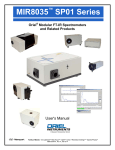
11 In the resulting spectrum, there should be a strong peak at
approximately 0.41 as shown in Figure 7. Multiply the peak
location by 28571. Subtract this product from 85714. This result
is the actual frequency of the PEM. Enter this value for the ‘PEM
Frequency in Hz’ parameter and then click Scan again. This value
may be different than the value on the PEM controller display.
Note the difference between the calculated value and the
displayed value. This difference will be constant.
700
dsp3 on fannie mae kevley udr4 pem=7500nm #2(128)
600
Response
500
400
300
200
100
0
-100
0.45
0.40
0.35
0.30
0.25
0.20
0.15
0.10
0.05
Wavenumber
Figure 7. Spectrum of time based raw data for step number 75Error! No bookmark name given.
12 When the scan is complete, select Spectrum 1 and Spectrum 5.
Go to Transforms > Fourier Transforms. Set Apodization
Function = TRIANGULAR and set Zero Function = TRIANGULAR
and set Zero Filling factor = 4 and then click OK to compute the
interferograms. Spectrum 5 should look similar to Figure 8.
PM-IRRAS Accessory Hardware Manual
29
Basic Operation
2800
PEM - real
2600
2400
2200
2000
1800
1600
Response
1400
1200
1000
800
600
400
200
0
3800
3600
3400
3200
3000
2800
2600
2400
2200
2000
1800
Wavenumber
1600
1400
1200
1000
800
600
400
200
Figure 8. AC spectrum (Ip–Is)
13 Select Spectrum 5 and go to Transforms > Spectral Calculator >
Paired Spectra. A ‘Spectral Arithmetic: Paired Spectra
Operations’ dialog box will be displayed. Select {/} Divide by
Reference. Select Use Current and then select 1. Phase
Modulation – Real from the list of spectra in the bottom right
corner. Click Replace.
14 Zoom in on Spectrum 5 between approximately 1500 and
900 cm-1. The spectrum should look similar to Figure 9 with a
large broad peak around ~1110 cm-1 and a weaker peak around
~1265 cm-1.
30
PM-IRRAS Accessory Hardware Manual
Basic Operation
1110.3
PEM - real
4.0
3.5
Response
3.0
2.5
1265.5
2.0
1.5
1500
1450
1400
1350
1300
1250
1200
1150
1100
1050
1000
950
900
Wavenumber
Figure 9. Ratio of AC spectrum (Ip–Is) to DC spectrum (Ip+Is)
PM-IRRAS Accessory Hardware Manual
31
Basic Operation
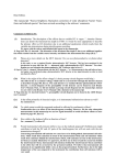
Data Collection in Rapid Scan Mode
1
Connect the hardware as shown in the schematic.
2F
Signal
Out
User 1
MCT
User 5
PEM CONTROLLER
Ext 1
LOCK-IN
AMPLIFIER
SPECTROMETER
Ref In
20 kHz HIGH
PASS FILTER
Input A
CH1 Output
KEY:
External Detector Cable
BNC Cable
BNC Connector
Figure 10. Schematic of cabling for rapid scan PM-IRRAS measurement
2
32
Go to Collect > Method Editor… Select the following parameters:
a
Common Settings:
Sample Scans = 64
Resolution = 8 cm-1
PM-IRRAS Accessory Hardware Manual
Basic Operation
3
b
Collect:
Speed = 12.5 KHz
UDR = 2
Filter = 3.2 KHz
Sensitivity = 1
Interferogram Symmetry = Asymmetric
Signal = User 1
Dual A/D Collect = checked
c
Spectrometer Configuration:
IR Source = Rear: Mid-IR
Beam Path = Right
Detector = Ext. 1
Aperture = 2 cm-1
Attenuator = 50%
SR830 Lock-in Amplifier
a
Time constant = 30 μs
b
Slope/Oct = 18 dB
c
Sensitivity = 1 x 1 V (variable)
d
Reserve = Normal
e
Signal Input
Input connector = A
Coupling = AC
Ground = Ground
f
Channel 1
Display = X
Ratio = off
Expand = off
Output = X
Press CH1 OFFSET Auto before each measurement
PM-IRRAS Accessory Hardware Manual
33
Basic Operation
g
Reference = Freq
h
Trig = Pos Edge
i
Press AUTO Phase before each measurement
4
Click Signal Monitor
5
Press and hold CH1 OFFSET AUTO on the lock-in amplifier to
remove any DC offset from the interferogram.
6
Adjust the sensitivity on the lock-in amplifier to achieve an
interferogram signal of 1–9 V.
7
Unplug the BNC cable from User 1 and plug it back into User 5.
8
On the Collect page of Method Editor make Signal = AUTO.
9
Click Scan.
10 At the end of the collect two spectra called Signal Channel and
Reference Channel will be added to the spreadsheet. The Signal
Channel corresponds to the AC spectrum (Ip–Is) from the lock-in
amplifier. The Reference Channel corresponds to the DC
spectrum (Ip+Is).
11 Select the Signal Channel spectrum in the spreadsheet and go to
Transforms > Spectral Calculator > Paired Spectra. A ‘Spectral
Arithmetic: Paired Spectra Operations’ dialog box will be
displayed. Select {/} Divide by Reference. Select Use Current
and then select the Reference Channel spectrum from the list of
spectra in the bottom right corner. Click Add.
12 The resultant spectrum should look similar to that shown in
Figure 9 on Page 31.
34
PM-IRRAS Accessory Hardware Manual
Maintenance
5. Maintenance
Cleaning
Fuses
Spare parts
35
36
36
This chapter includes maintenance procedures for the Polarization
Modulation Infrared Reflection Absorption Spectroscopy (PM-IRRAS)
Accessory that may be carried out by an operator. Any maintenance
procedures not specifically mentioned in this chapter or in the Help
should be carried out only by an Agilent-trained, Agilent-qualified or
Agilent-authorized customer service representative.
WARNING
Electrical Shock Hazard
This accessory contains electrical circuits, devices, and components
operating at dangerous voltages. Contact with these circuits, devices and
components can cause death, serious injury, or painful electrical shock.
Always follow the procedures described by Agilent.
Cleaning
Any spills on the PM-IRRAS should be immediately wiped up.
The exterior surfaces of the PM-IRRAS should be kept clean. All
cleaning should be done with a soft cloth. If necessary, this cloth can
be dampened with water or a mild detergent. Do not use organic
solvents or abrasive cleaning agents.
PM-IRRAS Accessory Hardware Manual
35
Maintenance
Fuses
The only user-accessible fuse in the PM-IRRAS is the mains inlet fuse
for the PEM controller. Refer to the PEM-100 User Manual for details.
Always turn off the power and remove the power cord before
replacing fuses. Fuses should be replaced only with the same type
and rated fuses as specified on the rear of the controller.
WARNING
Shock and Fire Hazards
This accessory contains electrical circuits, devices, and components
operating at dangerous voltages. Contact with these circuits, devices and
components can cause death, serious injury, or painful electrical shock. To
prevent reduced safety protection or unwanted fusing, ALWAYS ensure that
fuses are only replaced with fuses of the correct type and rating.
To check a fuse:
NOTE
1
Disconnect the instrument from the mains power supply.
2
Remove the fuse holder from the IEC mains power inlet
connector with a small flat blade screwdriver.
3
Check that the fuse is the correct type and is not damaged. If
necessary, replace the fuse.
4
Fit the fuse holder back into the IEC mains power inlet
connector.
5
Reconnect the instrument to the mains power supply.
If a fuse repeatedly blows, it may indicate other problems with the accessory.
A service call may be required.
Spare parts
For information about spare parts and their part numbers, refer to
the Agilent website, www.agilent.com
36
PM-IRRAS Accessory Hardware Manual
www.agilent.com
In This Guide
The guide describes the following:
Safety Practices and Hazards
Introduction
Hardware
Basic Operation
Maintenance
© Agilent Technologies 2010-2013
Printed in Malaysia
05/13
*8510258800*
*8510258800*
8510258800
Issue 5