1
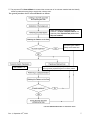
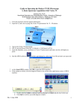
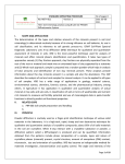
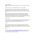
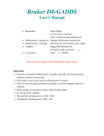
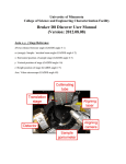
Bruker D8 Discover XRD User’s Guide
I. Powder Diffraction Measurement using LynxEye Detector
by Susheng Tan, Ph.D.
NanoScale Fabrication and Characterization Facility, University of Pittsburgh
M104 Benedum Hall, 3700 O’Hara Street, Pittsburgh, PA 15261
Phone: (412) 383-5978 Email: [email protected]
1. Fill in the Log-book with relevant information before you begin analyze your sample.
2. Check System Control Buttons (located at the front side of the system) and make sure the Ready and On
LED lights are on.
Stop Button: Emergency Stop!
If hit, it switches off the control electronics and high-voltage generator
immediately. The X-ray source is turned off, and all moving drives
will stop instantly.
Turn On/Off Illumination
Turn Off Power of the
This button turns the
Diffraction System: switches off
fluorescent lights located in
the control electronics, the high
the D8 enclosure on or off
voltage generator and all
components connected to the AC
outlets.
Turn On/Off Fan
Turn On Power of the
This button turns the fan on
Diffraction System: switches on
top of the D8 enclosure on
the control electronics, the high
or off.
voltage generator and all
components connected to the AC
outlets.
System Instrument – Key
High Voltage-Rotary Switch:
Switch: lock/unlock the
Turning the switch to the right
system. Can be removed in
position and hold it until the
the “locked” position.
orange status display (READY)
During normal operation the
starts flashing. The switch can be
switch must be “unlocked”.
released now.
Open Door Button
Under normal operating conditions the door handles are locked by a
mechanical shutter. To open the front door(s) this button must be
pressed. Then the front door(s) can be opened. If the Open Door button
is activated while the tube window is open, the X-ray shutter will close
automatically. After closing the front doors, the X-ray shutter can be
opened again.
3. Before opening the D8 door, check for any abnormalities in and around the instrument. Give particular
attention to the shutter lights on the X-ray tube. The green light indicates that the tube is energized (light
should be lit). The two red lights indicate the shutter position (if they are lit the shutter is open and you
must not open the doors on the D8; if the red lights are off, then it is safe to open the doors and mount the
sample stage on the goniometer).
4. Mount sample in the appropriate holder and then place the holder in the sample stage on the goniometer.
5. If the XRD COMMANDER is not opened, click the icon,
6. Set up DIFFRACplus XRD Commander
th
Rev. 4, September 25 , 2009
on the desktop to open it.
1
1) Click the Details tab to activate the Details page,
a. Select the PSD detector (LynxEye).
b. Input Discriminator Lower Level: 0.12; Discriminator Window Width: 0.14.
c. Click Set Detector button.
2) Activate the Adjust page
a. Make sure that for each drive its actual position is shown in blue. If any of the drive positions
are displayed in dark red, you will not be able to use the D8 — ask for help.
b. Set the X-ray generator voltage to 40 kV and the current to 40mA or other your desired
combination.
c. Find zero position of the Z drive for your sample:
i. Open the Video program by clicking the video icon,
, and start live view.
ii. In XRD Commander window, click Direct Mode icon,
to enter direct laser
control mode.
iii. In Direct Command window, type RC1 and press Enter to activate the direct laser
control mode.
iv. Type OC16,1 to turn the laser on.
v. Close the Direct Command window.
vi. Input a specific Z position and click the drive to icon,
to adjust the Z drive to
center the laser spot at the crosshair.
vii. Open the Direct Command window again, and type OC16,0 to turn off the laser.
viii. In Video program, stop Grab the live video.
3) Select measurement parameters:
a. scan type: Locked Coupled, continuous scan.
b. start: >3.5º , stop: <100º , scanspeed: 0.40 Sec/Step, and increment: 0.04º .
c. slit size: 0.2 mm; high voltage: 40 kV, current: 40 mA.
4) Click Start button,
to begin a measurement.
5) Click Stop button,
to end the immediate measurement.
7. After the scan is complete
1) Save the measured data as a RAW data file to your folder on the hard drive. XRD Commander
displays the Save As dialog box, and you must enter the RAW filename. The RAW data file can later
be examined (e. g., with EVA).
th
Rev. 4, September 25 , 2009
2
Note: by clicking the right mouse button inside the Chart area, you will bring a
popup menu:
• Apply Ident (applies the sample identification on the top axis)
• Print Chart
• Remove Peakstick
• Dots (shows the scan data as little dots instead of connected lines)
• Advanced (shows advanced customized options for the chart area such as
Save the chart data as a Text, XML, HTML, or Excel file).
Export→Data→Excel→Save As to your folder on the hard drive.
2) Set the X-ray tube voltage to 20 kV, current to 5mA
3) Minimize XRD Commander. Do not close the program.
II. Diffraction Evaluation using DIFFRACplus BASIC Evaluation
1. Double click the evaluation program icon,
Zoom pane
to open the EVA program.
Overview pane
Working pane
2. Creating EVA Documents
a. On the toolbar, click the Import button.
b. Locate the data .RAW file you want to import in the directory of your RAW files.
c. Click Open.
3. Working with Scans
a. Performing a Background Subtraction
i. The DIFFRAC traditional method: prepare data for search/match.
1) Click the Background button on the Data Treatment palette
2) Use the slider to adjust the curvature if there are background humps.
3) Select the Subtract from Scan check box.
4) Click Append to append the background-subtracted scan data to the document
ii. An enhanced method: gives a smooth curve.
iii. A Bézier method: allows you to draw the background exactly the way you want.
1) Draw a calculated background with the method above; get as close as you can
to the background you intend to draw.
2) Check the Bézier box to transform this background into curves.
th
Rev. 4, September 25 , 2009
3
b.
c.
d.
e.
3) Move the slider to adjust the curve to what you intend to draw.
4) Click Edit button to display all the control points: the passing points are disks,
the tangent points are squares, and the tangent vectors are in dashed lines. You
can move, erase, or add a passing point.
5) Check the Subtract box and then click on Append to create your drawn
background.
Performing a Peak Search
i. On the Data Treatment palette click the Peak Search button.
ii. Move the slider to see ghost peaks in the Overview and Working panes.
iii. When no manual editing is required, click Make DIF to transfer the found peaks to a
DIF pattern.
iv. When manual editing is required, click Append To List.
Computing Kα2 Stripping
i. Click the Strip Kα 2 button on the Data Treatment palette.
ii. Use the slider to adjust the Intensity Ratio.
iii. Click Append to append the Kα2 subtracted scan to the document
Smoothing Scans
i. Click the Smooth button on the Data Treatment palette.
ii. Use the slider to adjust the Smooth factor.
iii. Click Append to append the smoothed scan to the document
Fourier Smoothing and Expansion
i. Click the Fourier button on the Data Treatment palette.
ii. In the Fourier treatment control panel, select the expansion (x1, x2, x4, x8, and x16).
iii. Use the slider to adjust the cutoff.
iv. Click Append to append the smoothed scan to the document.
4. Search/Match:
(** see the next page for a general procedure.)
5. Saving and Printing in EVA.
6. Export file as ASCII file.
a. Export your EVA file as a RAW file;
b. Open the RAW File Exchange
, or XCH
files to ASCII files.
7. Exit EVA after you complete data processing.
8. Sign off the instrument by filling in the log-book.
th
Rev. 4, September 25 , 2009
, to convert your RAW and/or processed
4
** The purpose of EVA Search/Match is to search the current scan of an unknown material and then identify
reference patterns that are likely to explain the unknown scan.
The general procedure for EVA Search/Match is as follows:
Users are strongly encouraged to use
Criterion = 3: Favor Complex Patterns, no
chemistry filter, Experimental patterns and
Skip non ambient.
The best Figure of Merit
(FOM) is the lowest one.
Use Criterion = 1.
Prepare a residual scan by adapting the input scan and
removing already explained regions to ID minor phases.
Use the Scroll List mode to match the scan
th
Rev. 4, September 25 , 2009
5