1
3. Input Output connections and Jumper Settings
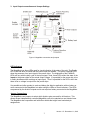
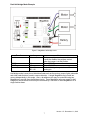
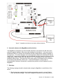
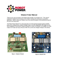
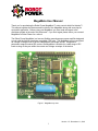
Figure 2. MegaMoto connections and jumpers
LED Indicators
The MegaMoto has three LEDs used for visual indication of the state of the unit. The Enable
LED is red and when lit shows that the power chips are enabled. The green PWMA/B LEDs
show the presence of an input signal to the power chips. The brightness of the PWMA/B
LEDs will vary with the duty cycle of the input signal. Note, these LEDs reflect the state of the
inputs to the power chips not the actual output voltage. It is possible for the power chip to be
in safety shutdown while receiving an input signal. Thus it is possible for the LED to be lit but
there to be no voltage is output from the power chips.
It is possible and often prudent to code and debug the Arduino application with no battery or
motor connected to the MegaMoto but rather using the LEDs as visual indicators. The LEDs
are powered by the Arduino outputs and do not require a battery connected to the MegaMoto.
Jumper Connections
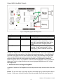
The MegaMoto uses jumpers to select which Arduino pins are used for all functions. This
allows several independently controlled MegaMoto units to be stacked on one Arduino base.
The MegaMoto also cooperates well with other shields that might have hard-wired pin
assignments.
Version 1.5 - December 11, 2010
3