1
VR2250
Instruction Manual
_____________________________________________________________MARVR2250
TABLE OF CONTENTS
1. SAFETY PRECAUTIONS AND PROCEDURES .......................................................................................... 4
1.1.
1.2.
1.3.
1.4.
Forward.................................................................................................................................................................... 4
Preliminary InstructionS ........................................................................................................................................... 4
During Use............................................................................................................................................................... 5
After Use.................................................................................................................................................................. 5
2. GENERAL DESCRIPTION ........................................................................................................................... 6
2.1. Introduction .............................................................................................................................................................. 6
2.2. Functions ................................................................................................................................................................. 6
3. PREPARATION FOR USE ........................................................................................................................... 7
3.1.
3.2.
3.3.
3.4.
Inspection ................................................................................................................................................................ 7
Power Supply........................................................................................................................................................... 7
Calibration................................................................................................................................................................ 8
Storage .................................................................................................................................................................... 8
4. INSTRUMENT DESCRIPTION ..................................................................................................................... 9
4.1. Display Description ................................................................................................................................................ 10
4.2. Initial Screen .......................................................................................................................................................... 10
4.3. Backlight function................................................................................................................................................... 10
5. INITIAL SETTINGS......................................................................................................................................11
5.1.
5.2.
5.3.
5.4.
How to Adjust the Contrast .................................................................................................................................... 11
How to Set Date and Time..................................................................................................................................... 11
How to Set the Language ...................................................................................................................................... 11
RESET................................................................................................................................................................... 12
6. SAFETY TEST FUNCTIONS.......................................................................................................................13
6.1. LOWΩ: Continuity Test with 200mA Test Current................................................................................................. 13
6.1.1.
6.1.2.
6.1.3.
6.1.4.
6.1.5.
Calibrating the test leads ("CAL" Mode) ..........................................................................................................................14
Measurement Procedure .................................................................................................................................................16
Results of "AUTO" mode .................................................................................................................................................16
Results of "RT+" and "RT-" modes ..................................................................................................................................17
"AUTO", RT+", "RT-" faulty cases....................................................................................................................................17
6.2. MΩ: Insulation resistance Measurement with 50V, 100V, 250V, 500V, 1000V Test Voltage ...................................... 19
6.2.1.
6.2.2.
6.2.3.
6.2.4.
Measurement Procedure .................................................................................................................................................19
Results of "MAN" mode ...................................................................................................................................................21
Results of "TMR" mode....................................................................................................................................................22
"MAN" and "TIMER" mode faulty cases...........................................................................................................................23
6.3. RCD: Test on "A" and "AC" Type RCDs ............................................................................................................... 24
6.3.1. Tripping times for the general and selective RCDs..........................................................................................................26
6.3.2. Measurement procedure..................................................................................................................................................27
6.3.3. RCD Faulty cases............................................................................................................................................................32
6.4. LOOP : Measurement of Line Impedance, Fault loop Impedance, Prospective Short Circuit Current Calculation
and Phase Sequence Indicator.............................................................................................................................. 37
6.4.1. Measurement procedure and results of "P-N" mode .......................................................................................................38
6.4.2. Measurement procedure and results of "P-P" mode........................................................................................................39
6.4.3. Measurement procedure and results of "P-PE" mode .....................................................................................................40
6.4.4. Measurement procedure and results of " RA " mode ...................................................................................................42
6.4.5. Measurement procedure and results of " " mode .......................................................................................................43
6.4.6. LOOP
Faulty Cases ..................................................................................................................................................44
6.5. EARTH: Soil Resistance and Resistivity Measurements ....................................................................................... 49
6.5.1. Measurement procedure and results of "2-W"and "3-W" mode.......................................................................................50
6.5.2. Measurement procedure and results of "ρ" mode ...........................................................................................................51
6.5.3. "2-W", "3-W" and "ρ" faulty cases....................................................................................................................................52
6.6. LEAKAGE CURRENT: REAL TIME MEASUREMENT.......................................................................................... 55
6.7. LEAKAGE CURRENT: RECORDING.................................................................................................................... 57
6.7.1. AUX Basic setting: RECORDER CONFIG.......................................................................................................................57
6.7.2. RECORDING: setting of Typical Configurations..............................................................................................................59
7. ANALYZER .................................................................................................................................................60
1
_____________________________________________________________MARVR2250
7.1. Basic Setting: ANALYZER CONFIG ...................................................................................................................... 61
7.1.1.
7.1.2.
7.1.3.
7.1.4.
7.1.5.
7.1.6.
Type of electrical system under test ................................................................................................................................61
How to set the fundamental frequency ............................................................................................................................61
How to set the current range ...........................................................................................................................................61
Clamp Type .....................................................................................................................................................................61
How to set the value of the transformer voltage ratio (TV RATIO) ..................................................................................61
How to enable/disable the password ...............................................................................................................................62
7.4.1.
7.4.2.
7.4.3.
7.4.4.
Symbols ...........................................................................................................................................................................70
"METER" mode................................................................................................................................................................71
"HARM" mode..................................................................................................................................................................72
"WAVE" mode..................................................................................................................................................................73
7.5.1.
7.5.2.
7.5.3.
7.5.4.
Symbols ...........................................................................................................................................................................74
“METER" mode................................................................................................................................................................75
“HARM" mode..................................................................................................................................................................76
"WAVE" mode..................................................................................................................................................................77
7.2. Basic Setting: RECORDER CONFIG .................................................................................................................... 63
7.3. ANALYZER FUNCTIONS ...................................................................................................................................... 70
7.4. "VOLTAGE" Function............................................................................................................................................. 70
7.5. "CURRENT" Function ............................................................................................................................................ 74
7.6. "POWER" Function ................................................................................................................................................ 78
7.6.1. Symbols ...........................................................................................................................................................................78
7.6.2. "METER" mode................................................................................................................................................................79
7.6.3. "WAVE" mode..................................................................................................................................................................80
7.7. "ENERGY" Function .............................................................................................................................................. 81
7.7.1. Symbols ...........................................................................................................................................................................81
7.7.2. "METER" mode................................................................................................................................................................82
7.8. Measuring Procedures........................................................................................................................................... 83
7.8.1. Using the Instrument in a Single Phase System..............................................................................................................83
7.8.2. Using the Instrument in a Three Phase System ..............................................................................................................84
8. SAVING RESULTS......................................................................................................................................85
8.1. Saving Safety Test Results.................................................................................................................................... 85
8.2. Saving Displayed Values of ANALYZER Function................................................................................................. 85
9. RECORDINGS.............................................................................................................................................86
9.1. Start a Recording................................................................................................................................................... 86
9.2. Setting Typical Configurations ............................................................................................................................... 87
9.2.1. Default Configuration .......................................................................................................................................................87
9.2.2. Typical Configurations .....................................................................................................................................................88
9.3. During a Recording................................................................................................................................................ 92
9.3.1. MENU key........................................................................................................................................................................92
9.3.2. Rotary Switch during a recording.....................................................................................................................................93
9.4. Stopping a Recording or an Energy Measurement ................................................................................................ 93
10. INSTRUMENT MEMORY ............................................................................................................................94
10.1. SAFETY TEST MEMORY...................................................................................................................................... 94
10.2. ANALYZER MEMORY........................................................................................................................................... 95
11. CONNECTING THE INSTRUMENT TO A PC.............................................................................................96
12. MAINTENANCE ..........................................................................................................................................97
12.1. General InstructionS .............................................................................................................................................. 97
12.2. Battery Replacement ............................................................................................................................................. 97
12.3. Instrument Cleaning............................................................................................................................................... 97
12.4. End of life............................................................................................................................................................... 97
13. TECHNICAL SPECIFICATIONS .................................................................................................................98
13.1. Technical Features ................................................................................................................................................ 98
13.1.1. ANALYZER and AUX functions .....................................................................................................................................100
13.2. Standards ............................................................................................................................................................ 101
13.2.1. General ..........................................................................................................................................................................101
13.2.2. Safety Test.....................................................................................................................................................................101
13.2.3. ANALYZER....................................................................................................................................................................101
13.3. General Specifications......................................................................................................................................... 102
13.3.1. Mechanical Data ............................................................................................................................................................102
13.3.2. Power supply .................................................................................................................................................................102
2
_____________________________________________________________MARVR2250
13.3.3. Display ...........................................................................................................................................................................102
13.3.4. Memory..........................................................................................................................................................................102
13.4. ENVIRONMENT .................................................................................................................................................. 102
13.5. ACCESSORIES................................................................................................................................................... 103
14. SERVICE ...................................................................................................................................................104
14.1. WARRANTY ........................................................................................................................................................ 104
.
104
14.2. SERVICE ............................................................................................................................................................. 104
15. APPENDIX 1 – MESSAGES DISPLAYED ................................................................................................105
16. APPENDIX 2 – RECORDABLE PARAMETERS: SYMBOLS...................................................................106
3
_____________________________________________________________MARVR2250
1. SAFETY PRECAUTIONS AND PROCEDURES
1.1.
FORWARD
This instrument conforms with safety standards EN61557 and EN 61010-1 relating to
electronic measuring instruments.
WARNING
For your own safety as well as that of the apparatus you are recommended to
follow the procedures described in this instruction manual and carefully read all
the notes preceded by the symbol .
Strictly adhere to the following instructions before and during measurements:
Do not take measurements in wet environments or dusty places.
Do not take measurements in environments with explosive gas or fuels.
Do not touch the wiring under test whilst taking measurements
Avoid any contact with exposed metal parts, ends of test leads not in use, circuits, etc.
Do not perform any measurement if the instrument is damaged, e.g, cracked case,
leaking batteries, absence of display reading etc.
Do not use the external power supply adapter (code MARVR2250PSU) if you notice
deformation, or damage to the case, wire or to the plugs.
Pay careful attention when measuring voltages exceeding 25V in places SUCH AS
building yards, swimming pools, etc. and 50V elsewhere, because of the risk of electric
shock.
Use only cables and accessories approved by Martindale Electric.
The following symbols are used in this manual:
Caution: refer to the instructions in this manual, improper use may damage the
apparatus or its components.
AC Voltage or Current.
Unidirectional pulsating Voltage or Current.
Rotary switch of the instrument.
1.2.
PRELIMINARY INSTRUCTIONS
This instrument has been designed for use in environments with a pollution level 2 and
up to (and no more than) 2000 meters altitude.
It can be used for Safety Test on Installation with Over voltage Category III 300V~
(phase to earth) and for voltage and current measurements on installations with over
voltage category III 600 V~ phase to phase / 300 V~ phase to earth or CATII 350 V
phase to earth.
4
_____________________________________________________________MARVR2250
Please keep to the usual safety standards aimed at:
♦ Protecting against dangerous currents;
♦ Protecting the instrument against improper use.
Only the accessories supplied with the instrument guarantee compliance with the
safety standards. Accordingly, they must be in good condition and, if necessary, they
must be replaced with identical models.
Do not take measurements on circuits exceeding the specified current and voltage
limits.
Before connecting cables, croc clips and clamps to the circuit under test, make sure
that the correct function has been selected.
Do not take any measurements under environmental conditions beyond the limits
specified in paragraph 13.4.
Check that batteries are not weak and have been inserted correctly.
Before connecting test leads to the circuit under test, check that rotary switch position
is correct.
Check that the LCD and the rotary switch indicate the same function.
1.3.
DURING USE
Please read carefully the following recommendations and instructions:
WARNING
Non compliance with the warnings and / or instructions may damage the
apparatus and / or its components, or injure the operator.
Before selecting any function, disconnect the test leads from the circuit under test.
When the instrument is connected to the circuit under test do not touch any unused test
leads.
Avoid taking resistance measurements in the presence of external voltages, even
though the instrument is protected, too high a voltage may cause malfunctions.
When measuring current, other currents near the test leads may affect the measuring
accuracy.
When measuring current, always position the wire in the middle of the current clamp
jaws in order to obtain the highest accuracy.
A measured value remains constant if the "HOLD" function is active. Should you notice
that the measured value remains unchanged, disable the “HOLD” function.
WARNING
The symbol "
" shows the battery status: When it is completely black the
batteries are fully charged, while the "
" symbol indicates weak batteries.
When the batteries are too low to execute the test the instrument will show a
warning message. In this case interrupt testing and replace batteries following
the procedure described under paragraph 12.2. The instrument is capable of
keeping the data stored even though batteries are not installed. The
Instrument Date and Time settings are not lost if you change the batteries
within 24 hours.
1.4.
•
•
AFTER USE
After use, turn off the instrument by pressing ON/OFF for a few seconds.
Remove batteries when the apparatus remains unused for long periods. Please follow
the storage instructions described at paragraph 13.4.
5
_____________________________________________________________MARVR2250
2. GENERAL DESCRIPTION
2.1.
INTRODUCTION
The instrument you have just purchased will grant you accurate and reliable
measurements provided that it is used according to these instructions.
The instrument was designed to grant the user the highest level of safety thanks to an
innovative design assuring double insulation and over voltage category III.
2.2.
FUNCTIONS
The instrument is able to perform the following tests:
LOWΩ:
Continuity Test of Earth, Protective and Equalising conductors with test
current higher than 200mA and open circuit voltage ranging from 4V to 24V.
MΩ:
Measurement of insulation resistance with DC test voltage 50V, 100V,
250V, 500V or 1000V.
RCD:
Measurement on general and/or selective RCD’s AC type (
) and A
type (
) of the following parameters:
Tripping time.
Tripping current.
Contact voltage (Ut).
Overall earth resistance (Ra).
In this mode the instrument can measure the overall earth resistance
without causing RCD tripping.
LOOP
:
EARTH
AUX:
ANALYZER:
Measurement of line and fault loop impedance with calculation of
prospective short circuit current,
Measurement of fault loop impedance between phase and earth and
Global Earth resistance measurement without RCD tripping
Calculation of prospective short circuit current, indication of phase
rotation sequence
Measurement of Earth Resistance and Resistivity using earth rods.
For future use
The instrument allows the following operations:
Display in real time the electrical parameters of single phase systems
and the harmonic analysis of voltage and current.
Conduct a direct Energy measurement (without memorising).
Memorise (pressing SAVE key) the sampled values of the parameters
present at instrument input generating an "Smp" record in instrument
memory. It will be possible to analyse the memorised data ONLY
by transferring the data to a PC.
Record simultaneously (pressing the START key after setting
parameters): RMS values of voltage, current, corresponding
harmonics, active, reactive and apparent powers, power factors and
cosϕ, active, reactive and apparent energies, voltage anomalies
(voltage sag and surge) with 10ms resolution. It will be possible to
analyse the recorded data ONLY by transferring the data to a PC.
WARNING
Please note the difference between memorise and record. These terms
will be used repeatedly in this manual. Please focus on their definitions and
distinctions.
6
_____________________________________________________________MARVR2250
3. PREPARATION FOR USE
3.1.
INSPECTION
This instrument has been checked mechanically and electrically prior to shipment.
Every care has been taken to ensure that the instrument reaches you in perfect condition.
You are recommended, however, to check for any possible damage which might have
been caused during transport. Should this be the case, immediately contact the distributor.
Check that the packaging contains all the parts listed under paragraph 13.5. In case of
discrepancies contact the distributor.
In the unlikely event that you have to send the instrument back, please follow the
instructions detailed in section 14.
3.2.
POWER SUPPLY
The instrument can be powered by:
6 batteries 1.5V AA - LR6 series located in the compartment on the back of the
instrument (not included in the package). For battery life see paragraph 13.3.1
An external power supply adapter (code MARVR2250PSU) to be used only for
ANALYSIS and AUX function. It is recommended that the MARVR2250PSU
Power Supply adapter is used for long-term measuring.
WARNING
For your own safety it is not permitted to use the external power supply
adapter during Safety Test (LOWΩ, MΩ, RCD, LOOP, EARTH rotary
switch positions). If you press the START button the Instrument will show
the message "
REMOVE POWER".
The symbol
shows the battery status: If it is completely "black" the batteries are fully
charged, while the
symbol indicates weak batteries. When the batteries are too low
to execute the test the instrument will show a warning message.
In this case interrupt testing and replace batteries following the procedure described under
paragraph 12.2.
The instrument is capable of keeping the data stored even though batteries are not
installed. The instrument Date and Time settings are not lost if you change the batteries
within 24 hours.
7
_____________________________________________________________MARVR2250
WARNING
For recordings (ANALYSIS and AUX function) it is recommended to
ALWAYS use the external power supply adapter (code MARVR2250PSU),
although the instrument does allow the operator to perform a recording
using internal batteries. If during a recording the external power supply
adapter is de-energised, the instrument will continue the recording using the
internal battery power until the batteries are exhausted (the data stored up
to the point the instrument shuts down will be saved). It is recommended to
ALWAYS insert a new set of batteries before a long recording.
The instrument uses sophisticated algorithms to prolong the battery life. Particularly:
The instrument switches OFF the backlight automatically after 5 seconds.
If the instrument is displaying in real time (and the external power supply adapter is not
connected), after about 5 minutes from the last key press or switch rotation the
instrument turns off automatically ("AUTOPOWER OFF" feature).
If the instrument is recording or is measuring energy (and the external power supply is
not connected), after about 5 minutes from the last key pressure or switch rotation the
instrument starts a special procedure to save the batteries ("ECONOMY MODE"): the
instrument keeps recording but the display is turned off.
3.3.
CALIBRATION
The instrument fulfils the technical specifications listed in this manual. The performance of
the specifications is guaranteed for one year.
Annual calibration is recommended.
Please call 01923 441717 for details.
3.4.
STORAGE
In order to ensure the accuracy of the measurements, after a period of storage in extreme
environmental conditions, wait until the apparatus is back to normal measuring conditions
(see environmental specifications listed in paragraph 13.4).
8
_____________________________________________________________MARVR2250
4. INSTRUMENT DESCRIPTION
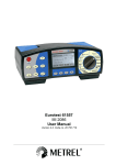
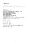
LEGEND:
1
1. Display
2. Function Keys
3. Rotary switch
2
F1
F2
F3
F4
3
START
STOP
F1 F2 F3 F4
ON/OFF
SAVE
HOLD
ENTER
MENU
ESC
Multifunction Keys.
ON/OFF and backlight key. Press for a few seconds to switch ON the
instrument, press it briefly to activate the backlight function.
START
STOP
This key is used to start and stop the measurement.
SAVE
This key allows you to save the result displayed.
HOLD
ENTER
This key has a double function. It is the confirmation key for the
configuration menu and it allows you to freeze the displayed results using
the ANALYZER function.
MENU
This key opens the General Configuration Menu.
ESC
This key allows you to quit the configuration menu or the selected
working mode.
9
_____________________________________________________________MARVR2250
4.1.
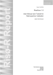
DISPLAY DESCRIPTION
The display is a graphic module with a resolution of 128 x 128 pixels
The first line of the display shows the function selected and the date and time. If not
correct, these can be set according to the procedure described at paragraph 5.2.
On the top right corner of the display you can always see the battery indicator and, if the
external power supply adapter (code MARVR2250PSU) is connected, the corresponding
symbol is displayed.
LOWΩ
27.09.00
05.06.01
17:35:12
VOLTAGE
SINGLE PHASE
----Ω
R+
----Ω
---mA
V1
Vpk1
ThdV
freq
R----Ω
---mA
AUTO 0.11Ω
FUNC
CAL
HARM
=
=
=
=
230.2 V
325.5 V
0.0
%
50.0 Hz
WAVE
These symbols will be omitted in the following illustrations.
4.2.
INITIAL SCREEN
When turning on the instrument by pressing ON/OFF, this screen will appear for a few
seconds:
Veritest
2250
MARTINDALE
SN:00000000 V: X.XX
BAUD RATE 57600
CALIBRATION DATE
01.01.06
Here you can see:
•
•
•
•
Serial number of the instrument (SN :)
Firmware software release (V.X.XX :)
Transmission speed through serial RS232 (Baud Rate)
Calibration date (CALIBRATION :)
4.3.
BACKLIGHT FUNCTION
When instrument is turned on, briefly pressing the ON button will enable the backlight. The
light will be turned off automatically after 5 seconds.
If the batteries are too low the instrument will automatically disable the backlight function.
10
_____________________________________________________________MARVR2250
5. INITIAL SETTINGS
On pressing the MENU key the following screen will be displayed:
MENU GENERAL
SAFETY TEST MEMORY
ANALYZER MEMORY
RESET
ANALYZER CONFIG
RECORDER CONFIG
CONTRAST
DATE&TIME
LANGUAGE
↓
↑
It is not possible to enter the MENU during a recording or a Real Time Energy
measurement. Pressing this button during a recording will display the main recording
parameters (see paragraph 9.3.1)
5.1.
HOW TO ADJUST THE CONTRAST
By pressing the multifunction keys F1 and F2, position the cursor on the CONTRAST item
and confirm by pressing the ENTER key.
By pressing the multifunction keys F3 and F4, adjust the contrast (higher values
correspond to a higher contrast while lower values correspond to a lower contrast) and
press the ENTER key to SAVE the change or press ESC to quit without saving.
This setting will remain unchanged after turning off the instrument.
5.2.
HOW TO SET DATE AND TIME
By pressing the multifunction keys F1 and F2, position the cursor on the DATE & TIME
item and confirm it by pressing the ENTER key.
The time is expressed as hh:mm (2 digits for hours, 2 digits for minutes) 24 hour clock.
Press the ENTER key to SAVE the change or press ESC to quit without saving.
This setting will remain unchanged also after turning off the instrument.
5.3.
HOW TO SET THE LANGUAGE
By pressing the multifunction keys F1 and F2, position the cursor on the desired language
and press the ENTER key to SAVE the change or press ESC to quit without saving.
This setting will remain unchanged after turning off the instrument.
11
_____________________________________________________________MARVR2250
5.4.
RESET
This option re-establishes the initial settings of the instrument in ANALYZER function.
The “Current Range” parameter is not modified by the reset command.
The initial settings of the instrument consist of:
ANALYZER CONFIG:
System:
Frequency:
Current range:
Clamp type:
Transforming ratio of voltage transformers:
Password:
SINGLE
50Hz
not modified
STD
0001
OFF
RECORDER CONFIG:
Start:
MANU (the recording is started
at 00 sec mark on clock after pressing
the START/STOP key)
Stop:
MAN
Integration period:
15min
Recording of harmonics:
ON
Recording of Voltage anomalies (Sag and Surge):
ON
Voltage Reference for Sag and Surge detection:
230V
Upper Limit for Sag and Surge detection:
6%
Lower Limit for Sag and Surge detection:
10%
Selected voltages:
V1
Selected voltage harmonics:
THD, 01, 03, 05, 07
Selected currents:
I1
Selected current harmonics:
THD, 01, 03, 05, 07
CO-GENERATION:
OFF
Powers, Pf and cosϕ selected:
P1
Q1i
Q1c
S1
Pf1
DPf1
Energies:
Ea1
Eri1
Erc1
Es1
The RESET command will not erase the instrument’s memory.
12
_____________________________________________________________MARVR2250
6. SAFETY TEST FUNCTIONS
6.1.
LOWΩ:
CONTINUITY TEST WITH 200mA TEST CURRENT
The measurement is performed according to EN 61557-2 and VDE 0413 part 4.
WARNING
Before carrying out the continuity test make sure that there is no voltage at the
ends of the conductor under test.
Turn the switch to the LOW Ω position.
This key permits you to select one of the following measuring modes:
Mode "AUTO" (the instrument carries out two measurements with
reversed polarity and displays their average value). This mode is
recommended for the continuity test.
Mode "RT+" (measurement with positive polarity and adjustable test
time). The operator can set a measuring time long enough to permit him
to move the protective conductors while the instrument is carrying out the
test, enabling detection of any bad connections.
Mode "RT-" (measurement with negative polarity and adjustable test
time). The operator can set a measuring time long enough to permit him
to move the protective conductors while the instrument is carrying out the
test, enabling detection of any bad connections.
This key executes the "CAL" mode (compensation of the resistance of the
test leads used for the measurement).
WARNING
If the resistance is lower than 5Ω (including the resistance of the test leads)
the continuity test is conducted with a test current higher than 200mA. If the
resistance is higher than 5Ω the continuity test is conducted with a current
lower than 200mA.
We recommend that you check the calibration of the test leads before executing a
measurement, according to the next paragraph (6.1.1).
13
_____________________________________________________________MARVR2250
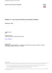
6.1.1. Calibrating the test leads ("CAL" Mode)
1. Connect the Red and Black test leads to B1 and B4 input terminals
respectively.
RED
B1
B2
B3
B4
BLACK
Connection of the test leads during calibration procedure.
2. Short-circuit the measuring cable ends making sure that the conductive parts of the
croc clips make a good contact to each other (see previous picture).
3. Press the F2 key. The instrument carries out the calibration.
WARNING
Never disconnect the test leads when the message "MEASURING" is
displayed.
LOWΩ
05.06.01
----Ω
R+
----Ω
---mA
R----Ω
---mA
AUTO 0.11Ω
FUNC CAL
A numerical value
in this field means
that the instrument
has been
calibrated; this
value remains on
the display for
any further
measurement
even though the
unit is switched off
and on again.
4. At the end of the test, the result is stored and used as an OFFSET (that is to
say that it is subtracted from any continuity test carried out) for all the
subsequent measurements.
Note:
The instrument performs the calibration only if the resistance of the test leads is
lower than 5Ω.
14
_____________________________________________________________MARVR2250
TEST LEADS
6.1.1.1.
Before each measurement always make sure that the calibration is
applicable to the test leads in use. During a continuity test, if the resistance
value free of calibration (that is the resistance value is less than the
is displayed. The
calibration offset value) is negative, the symbol
calibration resistance value stored in the instrument memory is not
applicable to the test leads in use; therefore a new calibration must be
performed.
Procedure to reset test leads calibration parameters
To remove a stored
calibration you must
perform the calibration
procedure with a
resistance higher than
5Ω (for example, with
disconnnected test leads
LOWΩ
05.06.01
>99.9Ω
R+
----Ω
---mA
AUTO
FUNC
R----Ω
---mA
0.11Ω
CAL
15
Message >99.9Ω:
This means that the
instrument has
detected a resistance
higher than 5Ω,
therefore resetting
the calibration
parameters
_____________________________________________________________MARVR2250
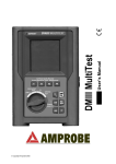
6.1.2.
Measurement Procedure
1. Select the desired mode by means of the F1 key.
2. Connect the Red and Black test leads to B1 and B4 input terminals respectively
B1
RED
P-E Conductor
B2
B3
B4
BLACK
Main Earth Connector
Connection of the test leads during LOW Ω test.
START
STOP
3. If the cables supplied with the instrument are not long enough for the measurement
you may extend the black cable.
4. Short-circuit the test leads making sure that the conductive parts of the croc clips
make a good contact with each other. Press the START key. If the display does
not show 0.00Ω, repeat the test lead calibration (see paragraph 6.1.1).
5. Connect the instrument terminals to the ends of the conductor under test (see
previous picture).
6. If the mode "RT+" or "RT-" was selected use the F3, F4 keys to set the
duration of the test.
7. Press the START key. The instrument will execute the measurement. In RT+/RT(Timer mode) you can press START key again if you want to stop the test before the
duration set has expired.
WARNING
Never disconnect the test leads when the message "MEASURING" is
displayed.
6.1.3. Results of "AUTO" mode
At the end of the test, if
the average resistance
value Ravg is lower
than 5Ω, the instrument
emits a double sound
signal indicating the
positive outcome of
the test and displays a
screen similar to this.
LOWΩ
05.06.01
1.05Ω
R+
1.07Ω
219mA
AUTO
FUNC
R1.03Ω
219mA
0.11Ω
Average resistance
value (Ravg)
Resistance values
and corresponding
test current when the
polarities of test
leads swapped.
CAL
The displayed result can be stored pressing the SAVE key twice
(see paragraph 8.1).
16
_____________________________________________________________MARVR2250
6.1.4. Results of "RT+" and "RT-" modes
If the resistance value
of RT+ or RT+ is lower
than 5Ω, the instrument
emits a double sound
signal indicating the
positive outcome of
the test and displays a
screen similar this.
LOWΩ
05.06.01
1.07Ω
Test current
219mA
RT+ 0.11Ω TIME: 10s
FUNC CAL
↑
↓
Note:
Max resistance value of
R+ or R-.
Duration of the test
We recommend that crocodile clips are used to achieve a good contact with the
conductor under test. In this test the instrument gives as a final result the maximum
measured value of R+ or R-, and using test leads instead of crocodile clips could give
an incorrect result due to bad contact between the test leads and conductor under
test.
The displayed result can be stored pressing the SAVE key twice
(see paragraph 8.1).
6.1.5. "AUTO", RT+", "RT-" faulty cases
If the instrument detects
the external power
supply adapter
connected the
instrument will display a
screen similar to this
LOWΩ
05.06.01
-.- -Ω
R+
---Ω
---mA
R---Ω
---mA
REMOVE POWER
AUTO
FUNC
If the terminal voltage is
higher than 15V, the
instrument does not
carry out the test, and
displays a screen similar
to this for 5 seconds.
Power Supply Adapter
0.11Ω
CAL
LOWΩ
Disconnect the External
05.06.01
-.- -Ω
R+
-.--Ω
---mA
R-.--Ω
---mA
VOLT IN INPUT
AUTO
FUNC
0.11Ω
CAL
17
ATTENTION: the test was
not performed because of
voltage at the terminals
_____________________________________________________________MARVR2250
In case that:
RCALIBRATION>RMEASURED
the instrument displays
the screen alongside.
LOWΩ
05.06.01
0.00Ω
R+
0.00Ω
219mA
R0.00Ω
219mA
ATTENTION:
RCALIBRATION >RMEASURED
CAL > RES
AUTO
0.11Ω
FUNC
CAL
THE PREVIOUS RESULTS CANNOT BE SAVED.
If
the
value
of
resistance is higher
than 5Ω (but lower than
99.9Ω) the instrument
emits a long sound
signal and displays a
screen similar to this.
LOWΩ
05.06.01
5.17Ω
R+
5.17Ω
209mA
R5.17Ω
209mA
Resistance value higher
than 5Ω
Test current
AUTO 0.11Ω
FUNC CAL
The displayed result can be stored pressing the SAVE key twice
(see paragraph 8.1).
If the value of the
resistance is higher
than
99.9Ω
the
instrument emits a long
sound
signal
and
displays a screen similar
to this.
LOWΩ
05.06.01
>99.9Ω
R+
>99.9Ω
---mA
AUTO
FUNC
R>99.9Ω
---mA
Resistance value higher than
99.9Ω
ATTENTION: Value of
resistance is out of range
0.11Ω
CAL
The displayed result can be stored pressing the SAVE key twice
(see paragraph 8.1).
18
_____________________________________________________________MARVR2250
6.2.
MΩ:
INSULATION RESISTANCE MEASUREMENT WITH 50V, 100V, 250V,
500V, 1000V TEST VOLTAGE
These measurements comply with IEC 61557-2 and VDE 0413 part 1.
WARNING
Before carrying out the insulation test, make sure that the circuit under test
is not energised and all the loads are disconnected.
Turn the switch to the MΩ position.
The key F1 selects one of the following measuring modes:
Mode "MAN" (Manual mode). Minimum test time of 5 secs, or for as long
as the start key is pressed. This is the recommended test.
Mode "TMR" (Timer mode: test duration depends on the selected interval
from 10 to 999 seconds). This test can be used if a minimum measuring
time is required.
6.2.1. Measurement Procedure
1. Select the desired mode by means of the F1 key.
2. Connect the test leads to the instrument input terminals B1 and B4 respectively,
RED
BLACK
M
I1
B1
B2
B3
B4
Example: insulation measurement between phase L1 and earth in a 3 PHASE electrical installation
using test leads.
3. If the cables supplied with the instrument are not long enough for the measurement
you may extend the black cable.
4. Connect the instrument terminals to the object which is to be submitted to the
insulation test after de-energizing the circuit under test and all loads
(see above).
5. By using F2, select the test voltage suitable for the type of test to be carried out
(see Table 1). The values that can be selected are:
•
•
•
•
•
50V (test on telecommunication system)
100V
250V
500V
1000V
19
_____________________________________________________________MARVR2250
Standard
Brief description
Test voltage
Maximum limit value
CEI 64-8/6
Systems SELV or PELV
Systems up to 500V
Systems over 500V
250VDC
500VDC
1000VDC
Floor and wall insulation
Floor and wall insulation in systems over 500V
Electrical panel boards 230/400V
Electrical equipment of machines
500VDC
1000VDC
500VDC
500VDC
> 0.250MΩ
> 0.500MΩ
> 1.0MΩ
> 50kΩ (se V<500V)
> 100kΩ (se V>500V)
> 230kΩ
> 1MΩ
CEI 64-8/4
EN60439
EN60204
Table 1:
Table 2:
Table for test voltages and the corresponding limit values for reference.
Rated voltage selected
for the test
RMAX = Maximum resistance
value
50VDC
100VDC
250VDC
500VDC
1000VDC
99.9MΩ
199.9MΩ
499MΩ
999MΩ
1999MΩ
Table of maximum resistance values which can be measured in MΩ
mode depending on the rated voltage selected.
6. If the "TMR" mode was selected, use the F3 and F4 keys to set the duration of
the test:
WARNING
Never disconnect the test leads from the circuit under test when the
message "MEASURING" is displayed, as the circuit under test may remain
charged at a dangerous voltage. The instrument has an internal "safety
resistor" which is connected to the output terminals before the end of the
test in order to remove any stored charge in the installation
START
STOP
7. Press the START key.
The instrument will start the test.
MAN Mode: The test will take 5 seconds (maximum). If the
START key pressed longer than 5 seconds, the test continues
until the key is released.
TMR mode: The test will take the time set. If you want to stop
the test press the START STOP key again.
20
_____________________________________________________________MARVR2250
6.2.2. Results of "MAN" mode
At the end of the test if
the insulation resistance
is lower than RMAX (see
Table 2) and the
instrument generated
the nominal test
voltage, the instrument
emits a double sound
signal indicating the
positive outcome of
the test and displays a
screen similar to this
MΩ
05.06.01
Insulation resistance
Voltage during the test
1.07MΩ
514V
MAN
FUNC
15s
500V
Duration of the test
Test mode
Test voltage set
VNOM
In order to evaluate the test you must compare the result with the limits indicated in the
guidelines (see Table 1 1 ).
The displayed result can be stored by pressing the SAVE key twice
(see paragraph 8.1).
If the Insulation
resistance is higher
than RMAX (see Table 2)
the instrument emits a
double sound signal
indicating the positive
outcome of the test
and displays a screen
similar to this.
MΩ
05.06.01
> 999 MΩ
523V
MAN
FUNC
15s
500V
Maximum resistance value
which can be measured.
(999Ω is displayed if a
rated voltage of 500V was
selected see Table 2).
The symbol ">" means that
the resistance value is
higher than RMAX .
Test duration
VNOM
The displayed result can be stored by pressing the SAVE key twice
(see paragraph 8.1).
21
_____________________________________________________________MARVR2250
6.2.3. Results of "TMR" mode
If the insulation
resistance is lower than
RMAX (see Table 2) and
the instrument
generated the nominal
test voltage, the
instrument emits a
double sound signal
indicating the positive
outcome of the test
and displays a screen
similar to this.
MΩ
05.06.01
Voltage during the test
1.07MΩ
514V
TMR
FUNC
Duration of the test
Test mode
15s
500V
Set time
TIME:60s
↑
VNOM
Insulation resistance
↓
The displayed result can be stored by pressing the SAVE key twice
(see paragraph 8.1).
If the Insulation
resistance is higher
than RMAX (see Table 2)
the instrument emits a
double sound signal at
the end of the test
indicating the positive
outcome of the test
and displays a screen
similar to this.
MΩ
05.06.01
> 999 MΩ
523V
TMR
FUNC
The symbol ">" means that
the resistance value is
higher than RMAX .
15s
500V
TIME:60s
VNOM
↑
Maximum resistance value
which can be measured
(999Ω is displayed if a
rated voltage of 500V was
selected. See Table 2).
Test duration
↓
The displayed result can be stored by pressing the SAVE key twice
(see paragraph 8.1).
22
_____________________________________________________________MARVR2250
6.2.4. "MAN" and "TIMER" mode faulty cases
If the instrument
detects the external
power supply adapter
connected, it displays
a screen similar to
this.
MΩ
05.06.01
-.- - MΩ
---V
15s
REMOVE POWER
If the instrument
detects a voltage
between the input
terminals higher than
15V, the instrument
does not perform the
test and displays this
screen for 5 seconds.
MAN
500V
FUNC
VNOM
MΩ
Disconnect the external
power supply adapter
05.06.01
-.- - MΩ
---V
15s
VOLT IN INPUT
MAN
FUNC
ATTENTION: the test cannot be
executed. Check that the circuit is
not energised.
500V
VNOM
These results cannot be saved
If the instrument
cannot generate the
nominal test voltage,
it will emit a long
sound signal and
display a screen
similar to this.
MΩ
05.06.01
1.17 MΩ
107V
MAN
500V
FUNC
VNOM
15s
Insulation Resistance
ATTENTION: the test of
resistance RISO was performed
at a voltage value lower than
the set rated voltage. Low
insulation case. This occurs
under low insulation conditions
or in the presence of
capacitance on the installation.
Test Time
The displayed result can be stored by pressing the SAVE key twice
(see paragraph 8.1).
23
_____________________________________________________________MARVR2250
6.3.
RCD:
TEST ON "A" AND "AC" TYPE RCDS
The test is executed according to IEC61557-6, EN61008, EN61009, EN60947-2 B 4.2.4
and VDE 0413 part 6.
WARNING
The automatic check of the RCD causes tripping of the RCD itself. Therefore
check that all devices connected downstream of the RCD under test are
not damaged by power off. It is advisable to disconnect all the loads
connected downstream of the RCD, as they could add leakage currents to the
result, so making the test results void.
Turn the switch to the RCD position:
The F1 key selects one of the following measuring modes (which can be
shown cyclically when pressing the key):
Mode "AUTO" (the instrument performs the test automatically with a
leakage current equal to half, once and five times the value of the rated
current set). Recommended test.
Mode "x ½" (the instrument performs the test with a leakage current
equal to half the value of the rated current set).
Mode "x 1" (the instrument performs the test with a leakage current equal
to the value of the rated current set).
Mode "x 2" (the instrument performs the test with a leakage current equal
to twice the value of the rated current set).
Mode "x 5" (the instrument performs the test with a leakage current equal
to five times the value of the rated current)
Mode " " (the instrument performs the test with a steadily increasing
leakage current. Use this test to measure the tripping current).
Mode "RA " (the instrument performs the test with a leakage current
equal to half the value of the selected rated current and calculates the
contact voltage as well as the Ra earth resistance).
N.B. The AUTO mode executes the test automatically with phase 0° and 180°
RCD Type
0° Current Waveform 180° Current Waveform
AC type
A type
According to standard practice it is recommended to perform the RCD test
both with phase 0° and with phase 180° even with non AUTO modes. If the
RCD under test is type A (which means sensitive to both AC and
undirectional pulsing leakage currents) it is advisable to perform the test both
with sine wave and undirectional pulse current with phase 0° and 180°.
24
_____________________________________________________________MARVR2250
The F2 key selects one of the following rated tripping currents of the RCD
(which can be shown cyclically when pressing the key):
10mA.
30mA.
100mA.
300mA.
500mA.
The F3 key permits to select the RCD type (which can be shown cyclically
when pressing the key):
"
":
general RCD AC type (sensitive to sine leakage current)
"
"
": general RCD A type (sensitive to pulsating leakage current)
S": selective RCD AC type (sensitive to sine leakage current)
"
S": selective RCD A type (sensitive to pulsating leakage current)
Note if the test is performed on general RCDs the symbol “S” is NOT displayed
Note according to EN61008 the test on selective RCDs requires an interval between the
tests of 60 seconds (30 seconds in case of tests at ½ IΔn). A timer is displayed
indicating the waiting time for each step.
Example:
Test with AUTO mode on a RCD with IΔn=30mA.
a) The instrument performs the test at ½ IΔn 0°. The RCD must
not trip.
b) The instrument performs the test at ½ IΔn 180°. The RCD
must not trip. For a selective RCD a 30 seconds timer starts
before executing next test.
c) The instrument performs the test at IΔn 0°. If the RCD passed
the test, it must trip and the instrument shows the message
"RESUME RCD". The operator shall reset the RCD. For a
Selective RCD a 60 seconds timer starts before executing
the next test.
d) The instrument performs the test at IΔn 180°. Follow the
same procedure as described under c).
e) The instrument performs the test at 5IΔn 0°. Follow the same
procedure as described under c).
f) The instrument performs the test at 5IΔn 180°. Follow the
same procedure as described under c). The test is
completed.
The F4 key selects one of the following limit values for the contact voltage
(which can be shown cyclically when pressing the key):
50V (default)
25V.
WARNING
Never disconnect the test leads when the message "MEASURING" is
displayed.
25
_____________________________________________________________MARVR2250
6.3.1. Tripping times for the general and selective RCDs
Table of tripping times for IΔN x1, IΔN x2, IΔN x5 and AUTO tests.
If the parameters set on the instrument comply with the type of RCD under test (and
if the latter works properly) the tests x1, x2, and x5 SHALL cause the RCD tripping
within the times shown in the following table:
RCD type
IΔ N x 1
IΔ N x 2
IΔ N x 5
General
0.3s
0.15s
0.04s
Max tripping time in seconds
0.5s
0.20s
0.15s
Max tripping time in seconds
0.13s
0.05s
0.05s
Minimum tripping time in seconds
Selective S
Description
* For rated values IΔN ≥ 30mA the test current at five times is 0.25A.
For currents equal to ½ IΔN the RCD shall not trip in any case.
Table 3:
Table of tripping times for tests with leakage currents IΔN x1, IΔN x2, IΔN x5
and AUTO.
Note:
The above values apply to RCD’s manufactured to comply with BSEN61008. RCD’s which
are manufactured to comply with BS4293 are required to operate in 0.2s at IΔN x 1. It is
important that the user of this instrument is aware of the applicable tripping time (s) for the
RCD being tested.
Table of tripping times for ramp tests " ".
The instrument generates a leakage current growing step by step in a given time
interval.
The limit values for the tripping current are indicated in the following table:
Table 4:
RCD Type
IΔN ≤ 10mA
IΔN > 10mA
A
1,4 x IΔN
1,4 x IΔN
AC
IΔ N
IΔ N
Current limit value for "Ramp" Test
Note:
“MAN” 5 x IΔN and “AUTO” test modes are not available for RCD type A at 500mA and are
not required
26
_____________________________________________________________MARVR2250
6.3.2. Measurement procedure
1. Select the desired test parameter with the F1, F2, F3 and F4 keys.
2. Connect the Red, Green and Black connectors of the three-terminal mains cable or
of the split cables to the corresponding input terminals of the instrument B1, B3, B4
1
Red
3
N
Black
Green
P
I1
B1
Red
B2
I1
B3
Green
B4
B1
Black
B2
B3
B4
Instrument connection for 400V + N + PE
three-phase RCD check
Instrument connection for 230V single-phase
RCD check
1
1
Red
3
N
3
Green
Red
Black
Green
Black
I1
I1
B1
B2
B3
B4
B1
B2
B3
B4
Instrument connection for 400V + PE (no N)
three-phase RCD check
Instrument connection for 400V + N (no PE)
three-phase RCD check
3. Connect the mains plug or the test leads to the system under test according to
one of the diagrams above.
27
_____________________________________________________________MARVR2250
6.3.2.1. Results of "x½" mode
START
STOP
4. Press the START key once to execute a test with 0° Current waveform.
or
Press the START key twice to execute a test with 180° Current waveform.
WARNING
Never disconnect the test leads when the message "MEASURING" is
displayed.
If the RCD does NOT
trip the instrument emits
a double sound signal
indicating the positive
outcome of the test and
displays a screen similar
to this.
RCD
05.06.01
> 999 ms
FRQ=50.0Hz Ut= 1V
VP-N=231V VP-PE=231V
RCD OK
x1/2
FUNC
Working mode
IdN
Value of contact voltage Ut
detected referred to the
rated value of the RCD
current set.
OK: RCD passed the test.
⎯
50V
RCD
UL
30mA
The symbol ">" means that
the RCD did not trip.
RCD nominal current
Contact Voltage Limit value
RCD type
The test can be stored by pressing the SAVE key twice (see paragraph 8.1).
6.3.2.2. Results of "x1, x2, x5" mode
START
STOP
4. Press the START key once to execute a test with 0° Current waveform.
or
Press the START key twice to execute a test with 180° Current waveform.
WARNING
Never disconnect the test leads when the message "MEASURING" is
displayed.
If the tripping time is
within the limits in Table
3, the instrument emits a
double sound signal
indicating the positive
outcome of the test and
displays a screen similar
to this.
RCD
49 ms
FRQ=50.0Hz Ut= 2V
VP-N=231V VP-PE=231V
RCD OK
x1
FUNC
Working mode
05.06.01
IdN
Value of contact voltage Ut
detected referred to the
rated value of the RCD
current set.
OK: RCD passed the test.
⎯
50V
RCD
UL
30mA
Tripping time (expressed in
milliseconds).
RCD nominal current
Contact Voltage Limit value
RCD type
The test can be stored by pressing the SAVE key twice (see paragraph 8.1).
28
_____________________________________________________________MARVR2250
6.3.2.3. Results of "AUTO" mode
START
STOP
4. Press the START key once to execute the test. The instrument carries out the
following six tests with different values of rated current:
1/2IΔn with 0° current waveform (the RCD shall not trip).
1/2IΔn with 180° current waveform (the RCD shall not trip).
IΔn with 0° current waveform (the RCD trips, message "RESUME RCD").
IΔn with 180° current waveform (the RCD trips, message "RESUME RCD").
5IΔn with 0° current waveform (the RCD trips, message "RESUME RCD").
5IΔn with 180° current waveform (the RCD trips, end of the test).
The test is good if all values of tripping times are within the limits reported in
Table 3.
WARNING
Never disconnect the test leads when the message "MEASURING" is
displayed.
At the end of the test if
all six tests were
positive, the instrument
displays a screen similar
to this.
RCD
0°
x1/2 >999ms
05.06.01
180°
>999ms
Tripping time (expressed in
milliseconds).
Value of contact voltage Ut
detected referred to the
rated value of the RCD
current set.
x1
55ms
65ms
x5
20ms
30ms
FRQ=50.0Hz
VP-N=231V
Ut= 1V
VP-PE=231V
RCD OK
AUTO
FUNC
Working mode
OK: RCD passed the test.
30mA ⎯
50V
IdN
RCD
UL
Contact Voltage Limit value
RCD nominal current
RCD type
The test can be stored by pressing the SAVE key twice (see paragraph 8.1).
29
_____________________________________________________________MARVR2250
6.3.2.4. Results of "RAMP
START
STOP
" mode
4. Press the START key once to execute a test with 0° Current waveform.
Or
Press the START key twice to execute a test with 180° Current waveform.
The instrument generates a leakage current growing step by step for a given
time interval.
CAUTION
Never disconnect the test leads when the message "MEASURING" is
displayed.
At the end of the test, if
the RCD tripping current
is lower than IΔn (Type
AC) or 1.4IΔn (Type A
with IΔn >10mA) or 2IΔn
(Type A with IΔn ≤10mA),
the instrument emits a
double sound signal
indicating the positive
outcome of the test and
displays a screen similar
to this.
Working mode
Tripping Current
RCD
05.06.01
27mA
35ms
FRQ=50.0Hz
VP-N=231V
Ut= 1V
VP-PE=231V
RCD OK
FUNC
30mA ⎯
IdN
RCD
Tripping time (expressed in
milliseconds).
Value of contact voltage Ut
detected referred to the
rated value of the RCD
current set.
OK: RCD passed the test.
50V
UL
RCD nominal current
Contact Voltage Limit value
RCD type
The test can be stored by pressing the SAVE key twice (see paragraph 8.1).
If the parameters set on the instrument are consistent with the RCD under test, the ramp
test “ ” WILL CAUSE RCD TRIPPING WITH A CURRENT LOWER THAN OR EQUAL
TO THE SELECTED RATED DIFFERENTIAL CURRENT. Do not use this test to
compare the trip time with the trip current, as the RCD has to be tested for tripping time
with a current equal to and over that of the rated leakage current of the RCD.
30
_____________________________________________________________MARVR2250
6.3.2.5. Results of "RA
START
STOP
" mode
4. Press the START key once: the instrument carries out the test.
WARNING
Never disconnect the test leads when the message "MEASURING" is
displayed.
The RCD must NOT
trip and the instrument
emits a double sound
signal indicating the
positive outcome of
the test and displays a
screen similar to this.
RCD
05.06.01
12
FRQ=50.0Hz
VP-N=231V
Ω
Ut= 1V
VP-PE=231V
FUNC
Working mode
30mA ⎯
IdN
RCD
Earth
Resistance
Value of contact voltage Ut
detected referred to the
rated value of the RCD
current set.
OK: Contact voltage not
dangerous.
Ut OK
RA
Global
value
50V
UL
RCD nominal current
Contact Voltage Limit value
RCD type
The test can be stored by pressing the SAVE key twice (see paragraph 8.1).
31
_____________________________________________________________MARVR2250
6.3.3. RCD Faulty cases
6.3.3.1. Connection troubles
If the instrument detects
the external power
supply adapter
connected, it will display
a screen similar to this
RCD
05.06.01
- - - ms
FRQ=50.0Hz
VP-N=230V
Ut= ---V
Vp-PE=230V
REMOVE POWER
x1
FUNC
Should the instrument
detect that the phase
and/or neutral cables
are not connected to an
installation, a screen
similar to this displayed
when pressing START.
30mA ⎯
50V
IdN
RCD
UL
RCD
05.06.01
- - - ms
FRQ=50.0Hz
VP-N= 0V
Ut= ---V
Vp-PE= 0V
LOW VOLTAGE
x1
FUNC
Should the instrument
detect a voltage
between phase and
neutral higher than
250V, for example if the
black cable is connected
to an installation phase
conductor of a 400V
three-phase system, a
screen similar to this is
displayed
Disconnect the External
Power Supply Adapter
NO VOLTAGE detected
30mA ⎯
50V
IdN
RCD
UL
RCD
05.06.01
- - - ms
FRQ=50.0Hz
Ut= ---V
VP-N=401V VP-PE= 230V
HIGH VOLTAGE
x1
FUNC
30mA ⎯
50V
IdN
RCD
UL
32
HIGH VOLTAGE Detected
_____________________________________________________________MARVR2250
This screen is displayed
when the phase
conductor has been
reversed with the neutral
one.
The instrument does not
perform the test.
Exchange the red cable
with the black one.
Repeat the test
RCD
This screen is displayed
when the phase
conductor has been
exchanged with the
protective conductor.
The instrument does not
perform the test.
Reverse the phase to
earth connection in the
plug or exchange the
red cable with the green
one.
RCD
This screen is displayed
when in a 230V Phase
to Phase System the
black conductor was
reversed with respect to
the green one.
The instrument does not
perform the test.
Reverse the black and
green conductors.
RCD
05.06.01
- - - ms
FRQ=50.0Hz
Ut= ---V
VP-N=231V VP-PE=
0V
CHANGE P-N
x1
FUNC
Phase and Neutral
Conductors are reversed.
30mA ⎯
50V
IdN
RCD
UL
05.06.01
- - - ms
FRQ=50.0Hz
Ut= ---V
VP-N= 2V VP-PE= 230V
CHANGE P-PE
x1
FUNC
Phase and Protection
Conductors are reversed.
30mA ⎯
50V
IdN
RCD
UL
05.06.01
- - - ms
FRQ=50.0Hz
Ut= ---V
VP-N=130V VP-PE= 227V
CHANGE N-PE
x1
FUNC
30mA
⎯
IdN
RCD
33
50V
UL
Neutral and Protection
Conductors are reversed.
_____________________________________________________________MARVR2250
If a contact voltage Ut
higher than the
selected limit (UL) is
detected, the instrument
interrupts the test and
emits a long sound
signal at the end of the
test, and displays a
screen similar to this.
RCD
If the instrument detects
that the earth cable
(green) is not
connected, the screen
alongside is displayed
for 5 seconds..Check
the connections of the
PE conductor under
test.
RCD
- - - ms
FRQ=50.0Hz
Ut= ---V
VP-N=234V VP-PE= 234V
UT DANGEROUS
x1
FUNC
30mA ⎯
50V
IdN
RCD
UL
The instrument cannot
detect an efficient
protection circuit.
05.06.01
- - - ms
FRQ =50.0Hz
Ut= ---V
VP-N=234V VP-PE= 34V
NO PE
x1
FUNC
If the instrument gets
overheated, tests cannot
be carried out and the
message alongside is
displayed. Wait until the
screen reverts to the
initial display before
proceeding.
05.06.01
30mA
⎯
IdN
RCD
RCD
50V
Message “NO PE”: the
instrument cannot detect
an efficient protection
circuit.
UL
05.06.01
- - - ms
FRQ=50.0Hz Ut= ---V
VP-N=231V VP-PE= 230V
HOT
x1
FUNC
500mA ⎯
IdN
RCD
Message “HOT”: the
instrument has overheated.
50V
UL
THE PREVIOUS RESULTS CANNOT BE SAVED.
34
_____________________________________________________________MARVR2250
When using the RA
function, if a contact
voltage Ut higher than
the selected limit (UL)
is detected, the
instrument emits a long
sound signal at the end
of the test and displays
a screen similar to this.
RCD
05.06.01
1800Ω
FRQ=50.0Hz
Ut= 54V
VP-N=234V VP-PE= 34V
UT NOT OK
RA
FUNC
30mA
⎯
IdN
RCD
50V
UL
The instrument cannot
detect an efficient
protection circuit.
The test can be stored by pressing the SAVE key twice (see paragraph 8.1).
6.3.3.2.
RCD tripping "faulty cases"
If the RCD trips during
the preliminary test
(regardless of the
working mode) the
instrument displays a
screen similar to this.
RCD
05.06.01
- - - ms
FRQ=50.0Hz Ut= ---V
VP-N=231V VP-PE= 230V
RCD TRIPS
x1
FUNC
30mA ⎯
50V
IdN
RCD
UL
The RCD trips too early.
Check if the RCD nominal
current is correct.
Some leakage currents
may be present in the
installation. Disconnect all
the loads downstream of
the RCD.
THE PREVIOUS RESULTS CANNOT BE SAVED.
If during tests MAN x1,
x2, x5 and AUTO
(during x1 and x5 tests),
the RCD trips to break
the circuit outside the
limits reported in Table
3, the instrument emits a
long sound signal at
the end of the test and
displays a screen similar
to this.
RCD
05.06.01
487 ms
FRQ=50.0Hz Ut=
1V
VP-N=231V VP-PE= 230V
TIME NOT OK
x1
FUNC
30mA
⎯
IdN
RCD
50V
RCD tripping time.
ATTENTION: the tripping
time is higher than the
standard limit.
UL
The test can be stored by pressing the SAVE key twice (see paragraph 8.1).
35
_____________________________________________________________MARVR2250
If the RCD tripping time
is higher than the
instrument’s measuring
limits, the instrument
emits a long sound
signal at the end of the
test and displays a
screen similar to this.
RCD
05.06.01
>999 ms
RCD tripping time is
greater than the maximum
measurable time (it
depends on type of test,
see following table).
FRQ=50.0Hz Ut=
1V
VP-N=231V VP-PE= 230V
TIME NOT OK
x1
FUNC
30mA ⎯
50V
IdN
RCD
UL
ATTENTION: the tripping
time is higher than the
standard limit.
The maximum duration depends on the test type:
Test type
General RCD
MAN x1 test
999ms
MAN x2 test
200ms
MAN x5 test
50ms
" " test
300ms
During the ramp test
if the RCD tripping time
is higher than the limit,
the instrument emits a
long sound signal at
the end of the test and
displays a screen similar
to this.
RCD
.
Tripping Current
27mA
>300ms
Freq=50.0Hz
Ut=
1V
VP-N=231V
Vp-PE=230V
TIME NOT OK
FUNC
If during the ramp test
the RCD tripping current
is higher than IΔn (Type
AC) or 1.4 IΔn (Type A
with IΔn>10mA) or 2 IΔn
(Type A with IΔn≤10mA),
the instrument emits a
long sound signal at
the end of the test and
displays a screen similar
to this.
05.06.01
Selective RCD
999ms
250ms
160ms
30mA
IdN
⎯
RCD
RCD
50V
UL
05.06.01
> 42mA
>300ms
FRQ=50.0Hz
VP-N=231V
Ut=
1V
VP-PE=230V
CURRENT NOT OK
FUNC
Tripping time exceeds the
limit value
30mA
⎯
50V
IdN
RCD
UL
Maximum current
generated by the
instrument during the test
for general RCDs (the
value indicated is referred
to an AC type 30mA RCD,
in this case the maximum
current supplied is equal to
1.4xIΔN
ATTENTION:
The RCD tripping current is
higher than the nominal
value (IΔN=30mA was set in
the example).
The previous results can be be stored pressing the SAVE key twice
(see paragraph 8.1).
36
_____________________________________________________________MARVR2250
6.4.
LOOP
:
MEASUREMENT OF LINE IMPEDANCE, FAULT LOOP
IMPEDANCE, PROSPECTIVE SHORT CIRCUIT CURRENT
CALCULATION AND PHASE SEQUENCE INDICATOR
Turn the switch on LOOP
position.
The F1 key selects one of the following measuring modes:
Mode "P-N" (the instrument measures the impedance between the phase
and neutral conductors and calculates the phase to neutral prospective
short circuit current).
Mode "P-P" (the instrument measures the impedance between two
phase conductors and calculates the phase to phase prospective short
circuit current).
Mode "P-PE" (the instrument measures the impedance between the
phase and protective conductors and calculates the phase to earth
prospective short circuit current).
Mode "RA " (the instrument measures the impedance between the
phase and protective conductors with a test current of 15mA in order to
avoid RCD tripping and calculates the phase to earth prospective short
circuit current).
Mode " " (the instrument detects the Phase Sequence in a three-phase
system).
WARNING
Never disconnect the test leads when the message "MEASURING" is
displayed.
37
_____________________________________________________________MARVR2250
6.4.1. Measurement procedure and results of "P-N" mode
1. Select P-N mode by means of the F1 key.
2. Connect the Red, Green and Black connectors of the three-terminal mains cable or
of the split cables to the corresponding input terminals of the instrument B1, B3, B4.
1
Red
3
N
I
Green
Black
I
P
I1
I1
Red
B1
B2
B3
B1
B4
B2
B3
B4
Black
Green
Instrument connection for P-N in a 400V threephase system
Instrument connection for P-N test in a 230V
single-phase System
START
STOP
3. Connect the mains plug into a 230V 50Hz socket or the croc clips to the
conductors of the three-phase system (see previous pictures).
4. If possible disconnect all low impedance loads downstream of the point at which
the measurement is to be taken, as such impedances would be in parallel with
the line impedance to be measured.
5. Press the START key. The instrument starts the test.
WARNING
The measurement in a 230V system uses a test current of 6A approx. This
may cause the tripping of protective devices with nominal values lower than
10A. If necessary perform the test upstream of the protection. Never
disconnect the test leads when the message "MEASURING" is displayed.
At the end of the test
the instrument emits a
double sound signal
indicating that the test
completely correctly
and displays a screen
similar to this.
Working mode
LOOP
05.06.01
1.07Ω
215A
FRQ=50.0HZ
VP-N=231V
P-N
FUNC
VP-PE=231V
Value of phase to neutral line
impedance expressed in Ω.
Value of the phase to neutral
prospective short circuit
current expressed in
amperes calculated
according to the following
formula.
Z2Ω
Formula for calculation of prospective short circuit current:
U
I CC = N
Z PN
Where UN = Nominal phase to neutral voltage =
127 if Vmeas ≤ 150
230 if Vmeas >150 ≤ 250
This result can be stored by pressing the SAVE key twice (see paragraph 8.1).
38
_____________________________________________________________MARVR2250
6.4.2. Measurement procedure and results of "P-P" mode
1. Select P-P mode by means of the F1 key.
2. Connect the Red, Green and Black connectors of the three-terminal mains cable or
of the split cables to the corresponding input terminals of the instrument B1, B3, B4
1
3
N
Red
I1
B1
B2
B3
B4
Green
Black
Instrument connection for P-P test in a 400V three-phase system
START
STOP
3. Connect the mains plug into a 230V 50Hz socket or the croc clips to the
conductors of the three-phase system (see previous pictures).
4. If possible disconnect all low impedance loads downstream of the point at which
the measurement is to be taken, as such impedance would be in parallel with
the line impedance to be measured.
5. Press the START key. The instrument starts the test.
WARNING
The P-P measurements in a 400V system use a test current of 11.5A approx.
This may cause the tripping of protective devices with nominal value lower than
10A. If necessary perform the test upstream of the protection. Never
disconnect the test leads when the message "MEASURING" is displayed.
At the end of the test
the instrument emits a
double sound signal
indicating that the test
is correctly
terminated and
displays a screen
similar to this.
Working mode
LOOP
05.06.01
0.57 Ω
701A
FRQ=50.0HZ
VP-P=402V
VP-PE=231V
Value of phase to phase
impedance expressed in Ω.
Value of the phase to phase
prospective short circuit
current expressed in Amps
calculated according to the
following formula.
P-P
FUNC
Z2Ω
Formula for calculation of prospective short circuit current:
U
I CC = N
Z PP
127 if Vmeas≤ 150
Where UN= phase to phase voltage
230 if Vmeas >150V ≤260
400 if Vmeas> 260
This result can be stored by pressing the SAVE key twice (see paragraph 8.1).
39
_____________________________________________________________MARVR2250
6.4.3. Measurement procedure and results of "P-PE" mode
1. Select P-PE mode by means of the F1 key.
2. Connect the Red, Green and Black connectors of the three-terminal mains cable or
of the split cables to the corresponding input terminals of the instrument B1, B3, B4.
1
3
N
Red
I
Green
Black
I
P
I1
I1
Red
B1
B2
Green
B3
B1
B4
B2
B3
B4
Black
Instrument connection for P-PE in a 400V threephase system
Instrument connection for P-PE test in a 230V
single-phase System
1
3
Red
Green
Black
I1
B1
B2
B3
B4
Instrument connection for P-PE in a 400V three-phase system without Neutral conductor
START
STOP
3. Connect the mains plug into a 230V 50Hz socket or the croc clips to the
conductors of the three-phase system (see previous pictures).
4. The key F4 permits to select one of the following limit values for the contact
voltage (which can be shown cyclically when pressing the key):
50V (default).
25V.
5. Press the START key once to execute a test injecting a current in phase with
positive half wave of the voltage.
Press the START key twice to execute a test injecting a current in phase with
negative half wave of the voltage.
WARNING
The P-PE measurement in a 230V System uses a test current of 6A approx.
This may cause the tripping of protective devices with nominal value lower than
10A and will cause the tripping of an RCD device. If necessary perform the
test upstream of the protection or RCD. Never disconnect the test leads when
the message "MEASURING" is displayed
40
_____________________________________________________________MARVR2250
LOOP
At the end of the test
the instrument emits a
double sound signal
indicating that the test
completed correctly
and displays a screen
similar to this.
05.06.01
1.07 Ω
215A
Freq=50.0HZ
VP-N=231V
Vp-PE=231V
Value of phase to earth
resistance expressed in Ω.
Value of the phase to earth
prospective short circuit
current expressed in
amperes calculated
according to the following
formula.
P-PE
FUNC
Z2Ω
Working mode
Formula for calculation of prospective short circuit current:
U
I CC = N
Z PE
Where UN = Nominal phase to neutral voltage =
127 if Vmeas ≤ 150
230 if Vmeas >150V ≤ 250
This result can be stored by pressing the SAVE key twice (see paragraph 8.1).
41
_____________________________________________________________MARVR2250
6.4.4. Measurement procedure and results of " RA " mode
1. Select RA mode by means of the F1 key.
2. Connect the Red, Green and Black connectors of the three-terminal mains cable or
of the split cables to the corresponding input terminals of the instrument B1, B3, B4.
1
Red
3
N
Black
I
P
Green
I
I1
I1
Red
B1
B2
B3
B1
B4
Green
B2
B3
B4
Black
Instrument connection for P-PE in a 400V threeInstrument connection for P-PE test in a 230V
phase system
single-phase System
3. Connect the mains plug into a 230V 50Hz socket or the croc clips to the
conductors of the three-phase system (see previous pictures).
4. If possible disconnect all low impedance loads downstream of the point at which
the measurement is to be taken, as such impedance would be in parallel with
the line impedance to be measured.
5. The key F4 permits to select one of the following limit values for the contact
voltage (which can be shown cyclically when pressing the key):
50V (default)
25V.
START
6. Press the START key once to execute a test with “0°” test current.
STOP
or
Press the START key twice to execute a test with “180°” test current.
WARNING
The RA
measurement uses a test current of 15mA. This may cause the
tripping of 10mA devices. If necessary perform the test upstream of the device.
Never disconnect the test leads when the message "MEASURING" is
displayed.
At the end of the test
the instrument emits a
double sound signal
indicating that the test
completed correctly
and displays a screen
similar screen to this.
LOOP
05.06.01
2
Ω
115A
Freq=50.0HZ
VP-N=231V
Vp-PE=231V
Value of phase to earth
resistance expressed in Ω.
Effective value of the phase
to earth prospective short
circuit current expressed in
amperes calculated
according to the following
formula.
RA
Working mode
FUNC
UN
Z PE
127 if Vmeas≤150
230 if Vmeas >150V ≤ 250
Formula for calculation of prospective short circuit current:
Where UN = Nominal phase to neutral voltage =
I CC =
This result can be stored by pressing the SAVE key twice (see paragraph 8.1).
42
_____________________________________________________________MARVR2250
6.4.5. Measurement procedure and results of " " mode
mode by means of the F1 key.
1. Select
2. Connect the Red, Yellow and Green connectors of the split cables to the
corresponding input terminals of the instrument B1, B2, B3.
1
3
Red
Yellow
Green
I1
B1
B2
B3
B4
Instrument connection for Phase Sequence Detection in a 400V three-phase system
START
STOP
3. Press the START key to execute a test.
At the end of the test
the instrument emits a
double sound signal
indicating that the test
completed correctly
and displays a screen
similar to this.
LOOP
05.06.01
RST
FRQ=50.0HZ
VS-T=401V
VR-S=391V
VT-R=399V
Phase sequence OK
Value of the phase to phase
voltage
OK
FUNC
Working mode
This result can be stored by pressing the SAVE key twice (see paragraph 8.1).
43
_____________________________________________________________MARVR2250
6.4.6. LOOP
Faulty Cases
If the instrument detects
the external power
supply adapter
connected, the
instrument will show a
screen similar to this.
LOOP
05.06.01
- - -
Ω
---A
FRQ=50.0HZ
VP-N=231V
VP-PE=230V
Disconnect the External
Power Supply Adapter
REMOVE POWER
P-N
FUNC
Should the instrument
detect that the phase
and/or neutral cables
are not connected, a
screen similar to this is
displayed when pressing
START.
Z2Ω
LOOP
05.06.01
- - -
Ω
---A
FRQ=50.0HZ
VP-N= 1V
VP-PE=
0V
NO VOLTAGE detected
NO VOLTAGE
P-PE
FUNC
Should the instrument
detect a voltage
between phase and
neutral higher of 250V,
for example where the
black cable is connected
to an installation phase
conductor of a 400V
three-phase system, a
screen similar to this is
displayed.
50V
UL
Z2Ω
LOOP
05.06.01
- - -
Ω
---A
Freq=50.0HZ
VP-N=401V
VP-PE=230V
HIGH VOLTAGE detected
HIGH VOLTAGE
P-PE
FUNC
50V
UL
Z2Ω
44
_____________________________________________________________MARVR2250
A screen similar to this
is displayed when the
phase conductor has
been reversed with the
neutral one.
The instrument does not
perform the test.
Exchange the red cable
with the black one.
LOOP
- - FRQ=50.0HZ
VP-N=231V
VP-PE=
0V
CHANGE P-N
50V
UL
Z2Ω
LOOP
Phase and Neutral
conductors are reversed.
05.06.01
- - -
Ω
---A
FRQ=50.0HZ
VP-N= 1V VP-PE= 230V
Phase and Protective
conductors are reversed.
CHANGE P-PE
P-N
FUNC
This screen is displayed
when in a 230V Phase
to Phase System the
black conductor was
reversed with respect to
the green one.
The instrument does not
perform the test.
Reverse the black and
green conductors.
Ω
---A
P-PE
FUNC
A screen similar to this
is displayed when the
phase conductor has
been exchanged with
the protective conductor.
The instrument does not
perform the test.
Exchange the red cable
with the green one.
05.06.01
Z2Ω
LOOP
05.06.01
- - -
Ω
---A
FRQ=50.0HZ
VP-N=131V VP-PE= 227V
CHANGE N-PE
P-N
FUNC
Z2Ω
45
Neutral and Protection
conductors are reversed.
_____________________________________________________________MARVR2250
If a contact voltage Ut
higher than the
selected limit (UL) is
detected, the instrument
interrupts the test and
emits a long sound
signal and displays a
screen similar to this.
Should the instrument
detect an extremely high
earth resistance,
suggesting that there is
no earth protection, a
screen similar to this is
displayed.
Please check the
efficiency of PE
conductor and earth
installation.
If the instrument gets
overheated, tests cannot
be carried out and the
message alongside is
displayed. Wait until the
screen reverts to the
initial display in order to
proceed with
measurements.
LOOP
05.06.01
- - -
Ω
---A
FRQ=50.0HZ
VP-N= 1V
Vp-PE=
0V
Ut DANGEROUS
RA
FUNC
50V
UL
LOOP
05.06.01
- - -
Message “Ut”: the
instrument cannot detect
an efficient protection
circuit.
Ω
---A
FRQ=50.0HZ
VP-N=231V
Vp-PE= 40V
NO PE
P-PE
FUNC
50V
UL
Z2Ω
LOOP
Message “NO PE”: the
instrument cannot detect
an efficient protection
circuit.
05.06.01
- - -
Ω
---A
FRQ=50.0HZ
VP-N=231V
Vp-PE= 40V
HOT
P-P
FUNC
Z2Ω
46
Message
“HOT”:
the
instrument has overheated.
_____________________________________________________________MARVR2250
Using the " " mode, if
a Phase to Phase
voltage is lower than
100V, the instrument
displays a screen similar
to this.
LOOP
05.06.01
- - FRQ =50.0HZ VR-S=391V
VS-T= 0 V VT-R= 0V
LOW VOLTAGE
PHASE ROTATION
FUNC
Using the " " mode, if
the instrument detects
that two phases are
connected together, it
displays a screen similar
to this.
LOOP
Phase to phase
voltage is lower than
100V
05.06.01
- - FRQ =50.0HZ
VS-T= 0 V
VR-S=407V
VT-R=407V
PHASE DOUBLED
Two phases are
connected together.
PHASE ROTATION
FUNC
THE PREVIOUS RESULTS CANNOT BE SAVED.
47
_____________________________________________________________MARVR2250
If in modes P-P and P-N
the instrument carries
out the test and detects
a resistance higher
than 199.9Ω, a screen
similar to this displayed.
LOOP
05.06.01
>199.9 Ω
Message ">199.9" means
that the resistance
measured is higher than
the maximum measurable
---A
FRQ =50.0HZ
VP-N= 1V
Vp-PE=
P-N
FUNC
0V
Z2Ω
This result can be stored pressing the SAVE key twice (see paragraph 8.1).
If in modes P-PE, RA
the instrument carries
out the test and detects
a resistance to be
higher than 1999Ω, a
screen similar to this is
displayed.
LOOP
05.06.01
>1999 Ω
Message ">1999" means
that the Resistance
measured is higher than
the maximum measurable
---A
FRQ =50.0HZ
VP-N= 1V
Vp-PE=
0V
50V
UL
RA
FUNC
This result can be stored by pressing the SAVE key twice (see paragraph 8.1).
In the
mode, if the
voltage of one or more
phases is too low, the
instrument will show a
screen similar to this.
LOOP
05.06.01
Phase sequence incorrect
RTS
FRQ =50.0HZ
VR-S=391V
VS-T=
VT-R= 0V
NOT CORRECT
0V
Phase voltages
incorrect
FUNC
This result can be stored by pressing the SAVE key twice (see paragraph 8.1).
48
_____________________________________________________________MARVR2250
6.5.
EARTH:
SOIL RESISTANCE AND RESISTIVITY MEASUREMENTS
Turn the switch to the EARTH position.
The F1 key selects one of the following measuring modes (which can be
shown cyclically when pressing the key):
Mode "2-W" (the instrument measures the resistance between 2 points).
Mode "3-W" (the instrument measures the resistance using two auxiliary
earth rods).
Mode "ρ" (the instrument measures the ground resistivity).
At the end of each test, the instrument automatically shows the average value of Earth
Resistance or Earth Resistivity calculated on the basis of the measured values.
The F2 key clears the average value of Earth Resistance or Earth Resistivity and
the test counter.
WARNING
Never disconnect the test leads from the circuit under test when the
message "MEASURING" is displayed
49
_____________________________________________________________MARVR2250
6.5.1. Measurement procedure and results of "2-W"and "3-W" mode
1. Select "2-W" or "3-W" Earth measurement mode by means of the F1 key.
2. Connect the Red, Yellow, Green and Black cables to the corresponding input
terminals of the instrument B1, B2, B3, B4 (see possible connections in the following
pictures).
1
Black
Yellow
3
N
Yellow
1
1
3
N
3
N
Transf
Black
I1
Red
I1
B1
B2
B3
Red
B4
B1
Green
B2
B3
B4
Green
Connections for 2 point Earth Resistance
measurement
Connections for 3 point Earth resistance
measurement
Yellow
1
3
N
Black
I1
Red
B1
B2
B4
B3
Green
Connections for measuring the resistance between an extraneous conductive part and the earth
system
START
STOP
3. Press the START key. The instrument starts the test.
At the end of the test
the instrument emits a
double sound signal
indicating that the
test completed
correctly and displays
a screen similar to this.
EARTH
05.06.01
0.77 Ω
Vd= 1V
Test:04
RAVG=0.74Ω
FUNC
Voltage value of electrical
noise
Number of test
Average Value of Earth
Resistance calculated over
the Number of tests
displayed.
3-W
"3 Point" Working mode
Earth Resistance value
expressed in Ω.
CLR
4. The instrument will automatically show the average value of the earth resistance .
Press F2 to RESET this value and the test counter.
This result can be stored by pressing the SAVE key twice (see paragraph 8.1).
50
_____________________________________________________________MARVR2250
6.5.2. Measurement procedure and results of "ρ" mode
1. Select ρ measurement mode by using the F1 key.
2. Select the distance d between the earth rods by using the F3 and F4 keys.
3. Connect the Red, Green, Yellow and Black connectors of the single cables to the
corresponding input terminals of the instrument B1, B2, B3, B4.
I1
B1
Red
B2
B4
B3
Green
Yellow
d
d
Black
d
Instrument connection for Earth resistivity measurement
START
STOP
4. Press the START key. The instrument starts the test.
At the end of the test
the instrument emits a
double sound signal
indicating that the
test completed
correctly and displays
a screen similar to this.
EARTH
05.06.01
1.77 Ωm
Vd= 1V
CLR
Voltage value of electrical
noise
Number of test
Test:04
ρAVG=0.74Ω
ρ
FUNC
Earth resistivity value
expressed in Ωm.
DIST= 2m
↑
↓
Average value of earth
resistivity calculated over the
number of tests displayed.
"ρ" Working mode
5. The instrument will automatically show the average value of the earth resistance.
Press F2 to RESET this value and the test counter.
This result can be stored by pressing the SAVE key twice (see paragraph 8.1).
51
_____________________________________________________________MARVR2250
6.5.3. "2-W", "3-W" and "ρ" faulty cases
If the instrument detects
the external power
supply adapter
connected to the
instrument it will show a
screen similar to this.
EARTH
05.06.01
- - -Ω
Vd= ---V
Test:04
RAVG=0.74Ω
REMOVE POWER
3-W
FUNC
If the Instrument
detects a voltage value
higher than 5V the
instrument will show a
screen similar to this.
Disconnect the External
Power Supply Adapter
CLR
EARTH
05.06.01
- - -Ω
Vd= 230V
Test:04
RAVG=0.74Ω
VOLT IN INPUT
3-W
FUNC
The message "Rc
HIGH" indicates that
the instrument cannot
produce the minimum
current necessary for
the measurement.
Check that the
terminals are correctly
connected and that the
auxiliary earth rod
connected to B4 (black
conductor) has not
been inserted into
pebbly or poor
conductive ground.
Warning symbol: voltage
noise on input.
CLR
EARTH
05.06.01
- - -Ω
Vd= 1V
Test:04
RAVG=0.74Ω
Rc HIGH
3-W
FUNC
CLR
52
Message "Rc HIGH": Check
auxiliary earth rods.
_____________________________________________________________MARVR2250
The message "Rp
HIGH" indicates that the
instrument cannot
produce the minimum
current necessary for
the measurement.
Check that the terminals
are correctly connected
and the auxiliary earth
rod connected to B2
(yellow conductor) has
not been inserted into
pebbly or poor
conductive ground.
The message "Rp and
Rc HIGH" indicates that
the instrument cannot
produce the minimum
current necessary for
the measurement.
Check that the terminals
are correctly connected
and that the auxiliary
earth rod connected to
B2 (yellow conductor)
and B4 (black
conductor) have not
been inserted in a
pebbly or poor
conductive ground.
EARTH
05.06.01
- - -Ω
Vd= 1V
Test:04
RAVG=0.74Ω
Rp HIGH
3-W
FUNC
Message "Rp HIGH": Check
auxiliary earth rods.
CLR
EARTH
05.06.01
- - -Ω
Vd= 1V
Test:04
RAVG=0.74Ω
Rp and Rc HIGH
3-W
FUNC
Message "Rp and Rc HIGH":
Check auxiliary earth rods.
CLR
THE PREVIOUS RESULTS CANNOT BE SAVED.
53
_____________________________________________________________MARVR2250
If the instrument
detects a resistance
value higher than
1999Ω, it will display a
screen similar to this.
EARTH
05.06.01
>1999Ω
Message ">1999" means that
the resistance value is higher
than the maximum
measurable.
Vd= 1V
Test:04
RAVG=0.74Ω
3-W
FUNC
CLR
This result can be stored by pressing the SAVE key twice (see paragraph 8.1).
If the instrument
detects a resistivity
value higher than
1999kΩ, it will display a
screen similar to this.
EARTH
05.06.01
>1999kΩm
Message ">1999" means that
the resistivity value is higher
than the maximum
measurable.
Vd= 1V
Test:04
ρAVG=0.74kΩm
ρ
FUNC
DIST=5m
↑
↓
CLR
This result can be stored by pressing the SAVE key twice (see paragraph 8.1).
54
_____________________________________________________________MARVR2250
6.6.
LEAKAGE CURRENT: REAL TIME MEASUREMENT
This working mode allows the user to perform real time measurement and recording of
Leakage Current, using the External Flexible Clamp.
Turn the switch to the "AUX" position.
1. On pressing this key you will change the measuring unit of the instrument’s
input. The following possibilities will be displayed cyclically:
-mA
Others
(Instrument's input disabled)
(Leakage current)
(not supported)
2. Connect the External Flexible Clamp to the instrument's “I1” input.
3. Check if the selector on the probe or clamp is adjusted to the range set on the
instrument. Both ranges must be set to the same value.
Example of External probe
connections
I3
B1
B2
B3
B4
WARNING
Never leave probes connected to the instrument when not in use, even with the
probe switched off.
55
_____________________________________________________________MARVR2250
PE (Protection Cunductor)
PHASE
PE (Protection Cunductor)
SINGLE PHASE
LOAD OR
ELECTRICAL PLANT
NEUTRAL
I1
B1
B2
I1
B3
B1
B4
Indirect Leakage Current measurement
in a single phase system
NEUTRAL
B2
THREE PHASE
LOAD OR
ELECTRICAL PLANT
DISCONNECT
ADDITIONAL
GROUNDING
X
ENSURE
SAFE
WORKING
B3
B4
PE (Protection Cunductor)
PE (Protection Cunductor)
I1
B3
R
S
T
N
SINGLE PHASE
LOAD OR
ELECTRICAL PLANT
X
B2
Indirect Leakage Current measurement
in a three phase system
PHASE
B1
THREE PHASE
LOAD OR
ELECTRICAL PLANT
R
S
T
N
ENSURE
SAFE
WORKING
I1
B1
B4
Direct Leakage Current measurement in
a single phase system
B2
DISCONNECT
ADDITIONAL
GROUNDING
B3
B4
Direct Leakage Current measurement in
a three phase system
4. The Instrument shows in real time the values present at the inputs.
Example of screen.
05.06.01
11:43:04
AUX
In1=
Example of Input Signal 1
23 mA
In1
PG+
5. Press this key to enable/disable the HOLD function. When the HOLD function is
enabled, the word HOLD is displayed. This key is disabled during a recording. It
is not possible to run a recording if this function is enabled.
6. The displayed result can be stored by pressing the SAVE key twice
(see paragraph 8.1).
56
_____________________________________________________________MARVR2250
6.7.
LEAKAGE CURRENT: RECORDING
Before starting a recording we recommend the user checks that real time values are
correct, and then follow the measurement procedure described in paragraph 6.6.
In addition, it is fundamental that instrument settings correspond to the accessories in use.
For this we recommend that the user checks the instrument’s settings before executing an
AUX recording.
Please check the RECORDER CONFIG settings as follows:
MENU:
Press to enter the MENU mode and change the instrument settings. It
is not possible to enter the configuration MENU during a recording or
an energy measurement.
START/STOP: Press to record the selected parameters according to the
instrument’s settings (see chapter 9).
6.7.1. AUX Basic setting: RECORDER CONFIG
Place the rotary switch in the AUX position, press the MENU key, use the F1/F2 keys to
select the RECORDER CONFIG item and press the ENTER Key.
WARNING
It is not possible to enter the MENU during a recording or a Real Time
Energy measurement.
MENU GENERAL
SAFETY TEST MEMORY
ANALYZER MEMORY
RESET
ANALYZER CONFIG
RECORDER CONFIG
CONTRAST
DATE&TIME
LANGUAGE
↓
↑
In RECORDER CONFIG mode, it is possible to carry out the following operations:
•
Setting of Start/Stop recording mode (AUTO or MANUAL), and the hour and date of
Start/Stop (in AUTO mode).
• Setting of Integration Period, selectable from 5 sec to 60 min
Press ENTER to confirm each setting, or ESC to exit from RECORDER CONFIG menu.
The pages of the "RECORDER CONFIG" can be schematised as follows:
57
_____________________________________________________________MARVR2250
MENU
To select AUTOMATIC start/stop mode,
place the cursor on MANU, and select
AUTO mode by using F3 or F4.
The time and date are then displayed.
RECORDER CONFIG
START
MANU
STOP
MANU
INT. PERIOD: 15min
↓
↑
+
-
To revert to MANUAL mode, place the
cursor on AUTO and select MANU mode
using F3 or F4
Use the multifunction keys F1 and F2
to position the cursor on the desired
word and then use the multifunction
keys F3 or F4 to modify the value.
Press ENTER to confirm and keep
the settings made.
Press ESC to leave the Menu without
modifying the existing parameters.
The following table shows the description of each function inside the RECORDER
CONFIG menu:
Function
START:MAN
STOP:MAN
START:AUTO
STOP:AUTO
INT. PERIOD
Description
Advised settings
The recording of all the selected parameters will start at 00
seconds after pressing START/STOP.
The recording of all the selected parameters will be interrupted
manually by pressing START/STOP.
The recording of all the selected values will be started / interrupted
at the set dates and times. In order to start the recording the user
will have to press START/STOP to set the instrument in Stand-by
mode until the start date and time previously set.
The value of this parameter determines every how many seconds
15min
the values of the selected parameters will be memorised.
Available choices:
5sec,10sec,30sec,1min, 2min 5min, 10min, 15min, 30min, 60min.
☺
☺
☺
For messages displayed see Error! Reference source not found.
58
_____________________________________________________________MARVR2250
6.7.2. RECORDING: setting of Typical Configurations
The following “Typical Configurations” are selectable via RECORDER CONFIG menu:
Standard Configuration
LEAKAGE (I1)
Description
Setting of measuring and recording mode of Leakage current on I1 channel.
To activate the above configuration, follow this procedure:
1. Turn the rotary switch to “AUX”.
2. Press the MENU key. Use the F1 key to display the screen below:
MENU GENERAL
SAFETY TEST MEMORY
ANALYZER MEMORY
RESET
ANALYZER CONFIG
RECORDER CONFIG
CONTRAST
DATE&TIME
LANGUAGE
↓
↑
3. Press MENU key again. The instrument displays a screen as shown below (picture on
the left). In this way it is possible to select the desired configuration on I1 channel with
F1 or F2 key. NOTE that TEMP and HUMIDITY are not supported.
TYPICAL
CONFIG.
TYPICAL
CONFIG.
LEAKAGE(I1)
LEAKAGE (I1)
TEMP.°C(I1)
TEMP.°C(I1)
HUM %HR(I1)
HUM %HR(I1)
Data saved
↓
↑
↓
Configuration selection
↑
Confirmation of configuration selection
4. Press ENTER key. The instrument displays the message “Data saved” for a while to
confirm the configuration (see above picture on the right). The instrument will return to
the measuring mode and you can start recording by pressing START/STOP key.
59
_____________________________________________________________MARVR2250
7. ANALYZER
This function allows the following operations:
Display in real time the electrical parameters of a single phase system (with and
without neutral wire) and the harmonic analysis of voltage and current.
Conduct a direct energy measurement (without memorising).
Memorise (pressing SAVE key) the sampled values of the parameters present at the
instrument input generating an "Smp" record in the instrument memory. It will be
possible to analyse the memorised data ONLY by transferring the data to a PC.
Record simultaneously (pressing the START key after a proper setting): RMS values
of voltage, current, corresponding harmonics, active, reactive and apparent powers,
power factors and cosϕ, active, reactive and apparent energies, voltage anomalies
(voltage sag and surge) with 10ms resolution. It will be possible to analyse the
recorded data ONLY by transferring the data to a PC.
Record simultaneously (pressing the START key) values of Voltage and Current
values coming from test leads and clamp, using “Typical Configurations” with preprogrammed parameters inside the meter (see paragraph 9.2 ).It will be possible to
analyse the recorded data ONLY by transferring the data to a PC.
It is fundamental that the instrument settings correspond to the installation type under test
and the accessories in use. We recommend that the user checks the instrument’s settings
before executing an ANALYSIS measurement.
Select the ANALYZER position on the rotary switch. On pressing the MENU key the
following screen will be displayed:
MENU GENERAL
SAFETY TEST MEMORY
ANALYZER MEMORY
RESET
ANALYZER CONFIG
RECORDER CONFIG
CONTRAST
DATE&TIME
LANGUAGE
↓
↑
It is not possible to enter the MENU during a recording or a Real Time Energy
measurement.
Generally, to check the instrument’s settings you must check "ANALYZER CONFIG"
and "RECORDER CONFIG" items.
60
_____________________________________________________________MARVR2250
7.1.
BASIC SETTING: ANALYZER CONFIG
Place the rotary switch in the ANALYZER position, press the MENU key, use the F1/F2
keys to select the ANALYZER CONFIG item and press the ENTER Key.
The following screen will be displayed:
ANALYZER CONFIG
SYSTEM
:SINGLE
FREQUENCY:50HZ
CURRENT RANGE:1000A
CLAMP TYPE: STD
TV RATIO:0001
PASSWORD:ON
↓
↑
+
-
These settings can be confirmed by pressing the ENTER key or cancelled by pressing the
ESC key.
7.1.1. Type of electrical system under test
The parameter SYSTEM is fixed to "SINGLE" value as the VERITEST 2250 is only able to
analyse a Single Phase system.
7.1.2. How to set the fundamental frequency
Position the cursor on the corresponding word by pressing the F1/ F2 keys, and select the
network frequency between the possible values 50Hz and 60Hz by pressing the
multifunction keys F3 and F4. This parameter is important ONLY if the input voltage is too
low for the instrument to detect the frequency. (for example, only the clamps for the current
measurement are connected). In this case the instrument generates an internal
synchronism equal to the value of the set frequency.
7.1.3. How to set the current range
The value of this parameter must always be equal to the full scale of the current
clamp used to take the measurement. If a multi-scale clamp is used, the value of this
parameter must be equal to the scale selected on the clamp.
Set the desired value by pressing the multifunction keys F3 and F4.
7.1.4. Clamp Type
The value of this parameter shows that standard clamps (STD), and flexible clamps
(flexINT and flexEXT) may be used with this instrument.
7.1.5. How to set the value of the transformer voltage ratio (TV RATIO)
The instrument can also be interfaced with step-down transformers in the equipment under
test. It can display the value of the voltages present on the primary winding of these
transformers. To do this it will be necessary to set the value of the transformer winding
ratio from 2:1 to 3000:1. The default is set at 1:1 for measurements of non transformer
systems. Select “TV RATIO” in the ANALYZER CONFIG menu. Set the desired value by
pressing the multifunction keys F3 and F4.
61
_____________________________________________________________MARVR2250
7.1.6. How to enable / disable the password
The instrument is provided with password protection to avoid the accidental interruption of
recording or energy measurements. Once a recording or a direct energy measurement has
been started (with the option “PASSWORD” enabled), approximately 3 minutes from the
last key press or switch rotation the START/STOP key is disabled. To stop the recording, it
will be necessary to enter the password.
In order to enter the password (which is not changeable), press START/STOP then press
the multifunction keys in the following sequence (within 10 seconds):
F1, F4, F3, F2
If you wait more than about 10 seconds, the display will return to the meter mode and the
instrument will continue recording. If you enter the wrong password, the message “ERROR
PASSWORD” will be displayed under “PASSWORD”. After a few seconds the display will
return to meter mode and the instrument will continue recording. In order to enable/disable
this option the correct password will have to be entered. The display will then return to
meter mode, and START/STOP will have to be pressed again to stop the recording. You
will then need to re-enter the “ANALYZER CONFIG” menu and scroll up or down to the
item “PASSWORD: ON” using the multifunction keys F1 and F2. Then turn the password
off by pressing the multifunction keys F3 and F4.
62
_____________________________________________________________MARVR2250
7.2.
BASIC SETTING: RECORDER CONFIG
Place the rotary switch in the ANALYSER position, press the MENU key, use the F1/F2
keys select the RECORDER CONFIG and press the ENTER Key.
This option allows you to check and modify the recording parameters, and the selected
parameters (up to a maximum of 62 + Frequency). If the number of selected values
exceeds 63 the message "too many param" will be displayed. The RECORDER CONFIG
mode is divided into 4 separate sub-screens:
1st screen: This screen allows you to set the START/STOP mode (AUTO or
MANUAL), the START and STOP time if AUTO mode is selected, the
Integration Period value, the Enabling/Disabling of Voltage Anomalies
detection, the Enabling/Disabling of Harmonics detection. Press ENTER to
confirm the settings and go to the next screen.
Press ESC to leave the menu without modifying the existing parameters.
2nd screen: This screen is devoted to the settings relevant to the VOLTAGE recording.
Press ENTER to confirm the settings and go to the next page.
Press ESC to leave this screen without modifying the existing parameters.
From this page you can enter the sub-screen “Harmonics” by pressing the
F1/F2 keys to select ‘HARM REC’ and then the F3 key. You can then select
the voltage harmonics to be recorded.
Press ENTER to confirm the settings and leave the “Harmonics” menu.
Press ESC to leave the "Harmonics" menu without modifying the existing
parameters.
3rd screen: This screen is devoted to the settings relevant to the CURRENT recording.
Press ENTER to confirm the settings and go to the next screen.
Press ESC to leave this screen without modifying the existing parameters.
From this screen you can enter the sub-screen “Harmonics” by pressing the
F1/F2 keys to select ‘HARM REC’ and then the F3 key. You can then select
the current harmonics to be recorded.
Press ENTER to confirm the settings and leave the “Harmonics" menu.
Press ESC to leave the "Harmonics" without modifying the existing
parameters.
4th screen: Menu composed of two sub-screens devoted to the selection of the
POWERS and ENERGIES to be recorded. From this screen you can enter
the sub-screen “POWER” and “ENERGY” by pressing the F1/F2 keys to select
‘POWER’ or ‘ENERGY’ and then the F3 key. You can then select the
parameters to be recorded.
When selecting the active powers for the recording, the corresponding active
energies will be automatically selected.
When selecting the reactive powers for the recording, the corresponding
reactive energies will be selected.
Press ENTER to leave this screen confirming the modifications made.
Press ESC to leave the "Menu" without modifying the existing parameters.
The various screens of the "RECORDER CONFIG" can be schematised as follows:
63
_____________________________________________________________MARVR2250
MENU
To select AUTOMATIC start/stop
mode, place the cursor on MANU, and
select AUTO mode by using F3 or F4.
The time and date are then displayed.
RECORDER CONFIG
START
MANU
STOP
MANU
INT. PERIOD: 15min
HARM REC: ON
ANOM REC: ON
↓
st
↑
+
-
1 screen of the RECORDER
CONFIG MENU
ENTER
Use the multifunction keys
F1, F2 to position the cursor
on the desired symbol and
use the multifunction keys
F3 / F4 to select / deselect
the desired parameter
(selected if marked in black).
Press ENTER to confirm and
leave the Menu keeping the
settings made.
Press ESC to leave this
page without modifying the
existing parameters.
To revert to MANUAL mode, place the
cursor on AUTO and select MANU
mode using F3 or F4
Use the multifunction keys F1 and
F2 to position the cursor on the
desired word and then use the
multifunction keys F3 or F4 to
modify the value.
Press ENTER to confirm and keep
the settings made.
Press ESC to leave the Menu
without modifying the existing
parameters.
RECORDER CONFIG
VOLTAGE:
V1
HARM. REC:Pg (ON)
Vref P-N: 230V
LIM+: 06% (243.8V)
LIM-: 10% (207.0V)
↓
↑
+
-
Example of 2nd screen with
ANOM flag enabled
If you want to change Voltage Harm, place the cursor on
the corresponding “Pg” symbol then Press F3
RECORDER CONFIG
VOLTAGE HARMONICS
ENTER
05
12
19
26
33
40
47
Thd
06
13
20
27
34
41
48
↓
DC
07
14
21
28
35
42
49
01
08
15
22
29
36
43
↑
02
09
16
23
30
37
44
+
03
10
17
24
31
38
45
04
11
18
25
32
39
46
-
Example of sub-screen
"VOLTAGE HARMONICS"
64
Use the multifunction keys F1,
F2 to position the cursor on the
desired voltage harmonic and
use the multifunction keys F3 /
F4 to select / deselect
(selected if highlighted in
black).
Press ENTER to confirm this
screen.
Press ESC to leave the Menu
without modifying the existing
settings.
The instrument will record the
values of the selected
harmonics corresponding to
the voltage selected in one of
the two screens of the
previous Menu.
_____________________________________________________________MARVR2250
From 2nd screen
of RECORDER CONFIG MENU
ENTER
RECORDER CONFIG
CURRENT:
I1
HARM. REC:Pg (ON)
↓
↑
+
-
Use the multifunction keys
F1, F2 to position the
cursor on the desired
word and use the
multifunction keys F3 / F4
to modify the value or
select / deselect the
desired parameter (it’s
selected if marked in
black).
Press ENTER to confirm.
Press ESC to leave the
Menu without modifying
the existing settings.
Example of 3rd screen
If you want to change Current Harm, place cursor on the
corresponding “Pg” symbol then Press F3
RECORDER CONFIG
CURRENT HARMONICS
ENTER
05
12
19
26
33
40
47
Thd
06
13
20
27
34
41
48
↓
DC
07
14
21
28
35
42
49
01
08
15
22
29
36
43
↑
02
09
16
23
30
37
44
+
03
10
17
24
31
38
45
04
11
18
25
32
39
46
-
Example of sub-screen
"CURRENT HARMONICS"
65
Use the multifunction keys F1,
F2 to position the cursor on the
desired current harmonic and
use the multifunction keys F3 /
F4 to select / deselect (it’s
selected if marked in black).
Press ENTER to confirm this
screen.
Press ESC to leave this page
without modifying the existing
settings.
The instrument will record the
values of the selected harmonics
corresponding to the currents
selected in one of the two
screens of the previous Menu.
_____________________________________________________________MARVR2250
From 3rd screen
of RECORDER CONFIG MENU
ENTER
RECORDER CONFIG
CO-GENERATION:ON
POWER:Pg
ENERGY:Pg
↓
↑
+
-
Example of 4th screen
In order to select the POWER to be recorded use the
multifunction keys F1, F2 to position the cursor on the
corresponding “Pg” Symbol and then press F3
ENTER
RECORDER CONFIG
P1
Pf1
Q1i
DPf1
Q1c
S1
↓
↑
+
-
Example of POWER sub-screen
WARNING
•
•
When selecting the active power for the recording, the corresponding active
energy will be automatically selected.
When selecting the reactive powers for the recording, the corresponding
reactive energies will be selected.
66
_____________________________________________________________MARVR2250
From 3rd screen
of RECORDER CONFIG MENU
ENTER
RECORDER CONFIG
CO-GENERATION:ON
POWER:Pg
ENERGY:Pg
↓
↑
+
-
Example of 4th screen
In order to select the ENERGIES to be
recorded use the multifunction keys F1, F2 to
position the cursor on the corresponding “Pg”
Symbol and then press F3
ENTER
RECORDER CONFIG
Ea1
↓
Eri1 Erc1 Es1
↑
+
-
Example of ENERGY sub-screen
in single-phase mode
WARNING
•
•
When selecting the active energy for the recording, the corresponding active
power will be automatically selected.
When selecting the reactive energies for the recording, the corresponding
reactive powers will be selected.
67
_____________________________________________________________MARVR2250
Symbols
START:MAN
STOP:MAN
START:AUTO
STOP:AUTO
INT. PERIOD
HARM REC.
ANOM REC.
V1
THD, DC, 01...49
Vref
(Only if ANOM. REC
flag has been set ON)
LIM+, LIM(Only if ANOM. REC
flag has been set ON)
I1
THD, DC, 01..49
Description
Advised settings
The recording of all the selected parameters will start at 00
seconds after pressing START/STOP (see chapter 9.1).
The recording of all the selected parameters will be interrupted
manually by pressing START/STOP (see chapter 9.1).
The recording of all the selected values will be started / interrupted at
the set dates and times. In order to start the recording the user will
have to press START/STOP to set the instrument in stand-by mode
until the start date and time previously set (see chapter 9.1).
The value of this parameter determines how many seconds will
15min
elapse before the values of all the selected parameters will be
memorised. Available choices:
5sec,10sec,30sec,1min,2min,5min,10min,15min,30min,60min.
ON = the instrument will record the values of the selected
voltage and current harmonics.
OFF = the instrument will not record any voltage or current
harmonic selected
ON = the instrument will record voltage anomalies (voltage sag
and surge)
OFF = the instrument will not record any voltage sag and surge
☺
☺
☺
☺
☺
☺
Voltage RMS value
V1
Voltage Total Harmonic Distortion, DC Component, 01 to 49
harmonics respectively.
☺
THD,01,03,05,07
☺
RMS reference value for voltage used in voltage anomalies
detection (voltage sag and surge). The reference is:
Single phase: 230V
a) Voltage Phase to Neutral for single phase and 4 wire three
3 Phase system:
phase system.
3 wires: 400V
b) Voltage Phase to Phase for 3 wire three phase system.
4 wires 230V
High and Low Voltage Percent threshold used in voltage
anomalies detection (voltage sag and surge). These parameters
can be adjusted in range 3% ÷ 30% (step 1%).
Example: Three Phase System 4 wire.
Vref = 230, LIM+= 6%, LIM-=10% =>
+6% / -10%
High Lim = 243.8V, Low Lim = 207.0V
The instrument will detect a voltage anomaly if the RMS voltage
values (calculated every 10ms) are beyond the above calculated
thresholds
☺
☺
Current RMS value.
I1
Current Total Harmonic Distortion, DC Component, 01 to 49
harmonics respectively
68
☺
THD,01,03,05,07
_____________________________________________________________MARVR2250
CO-GENERATION
ON = the instrument is able to manage CO-GENERATION of
electrical equipment (that is, the equipment under test is able
to generate energy besides absorbing it). Accordingly, the
instrument will record the powers and energies both absorbed
and generated. If this flag is enabled the maximum number
of parameters which can be selected decrease to 38.
OFF = the instrument will record ONLY the powers and energies
absorbed.
P1
Active Power
Q1i
Inductive Reactive Power
Q1c
P1
☺
Q1i Q1c
Capacitive Reactive Power
S1
Apparent Power
Pf1
Power factor
☺
☺
☺
S1
☺
DPft1
cosϕ
Ea1
Active energy
☺
Eri1
Inductive reactive energy
☺
Pf1 dPf1
Ea1
Eri1 Erc1
Erc1
Capacitive reactive energy
The value of the network frequency is automatically selected if the voltage is selected.
The symbols "i" and "c" stand for reactive powers (Q), power factors (Pf) and cosϕ (dpf) inductive and capacitive respectively.
When selecting a power factor (Pf) or a cosϕ (dPf) for recording the inductive value and the capacitive value will be recorded
separately.
For messages displayed see Error! Reference source not found.
69
_____________________________________________________________MARVR2250
7.3.
ANALYZER FUNCTIONS
For basic use, the main working mode of the ANALYZER mode can be selected
by means of F3 and F4.
"VOLTAGE" function:
"CURRENT" function:
"POWER" function:
"ENERGY" function:
to be used to display voltage and corresponding
harmonics (see paragraph 7.4)
to be used to display current and corresponding
harmonics (see paragraph 7.5)
to be used to display of all the parameters measurable
by the instrument: voltage, current, active, reactive and
apparent power, power factor, cosϕ and energy (see
paragraph 7.6)
to be used to display active, reactive and apparent
power, power factor, cosϕ and energy (see paragraph
7.7)
More practically, we may schematise the correct procedure for the ANALYZER function as
follows:
1.
2.
3.
4.
5.
Check, and if required, modify the "ANALYZER CONFIG" settings of the instrument
Using F3 and F4, select the type of measurement to be taken
Connect the instrument to the electrical system to be tested
Evaluate the values of the parameters under test
If you want to record:
a) Decide what to record
b) Press MENU and check if the "RECORDER CONFIG" settings meet your
requirements.
c) Consider Typical Configuration recording (see paragraph 9.2).
6. Connect the External Power Supply MARVR2250PSU (optional)
7. Start the recording by pressing START/STOP.
7.4.
"VOLTAGE" FUNCTION
This function permits you to display in real time the RMS value of AC/DC voltage,
the peak, the Thd value, the waveform and the harmonic spectrum of the voltage.
7.4.1. Symbols
The VOLTAGE position has three working modes:
METER
WAVE
HARM
These modes will be described in detail in the next paragraphs.
The symbols used are described below:
Symbol
V1
Vpk1
h01 - h49
ThdV
freq
Description
Voltage RMS value
Peak value of the voltage
Harmonic 01 - Harmonic 49.
Factor of total harmonic distortion of the voltage.
Network frequency
Table 1: Symbols used in the VOLTAGE function
70
_____________________________________________________________MARVR2250
7.4.2. "METER" mode
In this mode the instrument shows a screen similar to this, according to the settings made
as per paragraph 7.1.
27.09.00
17:35:12
VOLTAGE
SINGLE PHASE
V1
Vpk1
ThdV
Freq
HARM.
=
=
=
=
230.2 V
325.5 V
0.0
%
50.0 Hz
WAVE
PG-
PG+
Example of screen
The symbols used are described in Table.1
For messages displayed see Error! Reference source not found.
The following keys are enabled:
F1:
to select the "HARMONIC" mode (see paragraph 7.4.3).
F2:
to select the "WAVE" mode (see paragraph 7.4.4).
F3/F4:
to select the previous/next function respectively.
SAVE:
to save a record of “Smp” type in instrument memory (see paragraph
8.2) containing the instantaneous values of voltage and current
present on the instrument inputs. This function is disabled during a
recording.
ENTER/HOLD:
to enable/disable the HOLD function of the displayed data. All the
previous functions remain available. When the HOLD function is
enabled, the word HOLD is displayed. When this function is enabled
it is not possible to record or take an energy measurement. This
function is disabled during a recording or an energy measurement.
MENU:
to enter in the MENU mode and change the instrument settings (see
paragraph 7.1 and 7.2). It is not possible to enter the configuration
MENU during a recording or an energy measurement.
START/STOP:
to record the selected parameters according to the instrument’s
settings (see chapter 9).
71
_____________________________________________________________MARVR2250
7.4.3. "HARM" mode
On selecting the HARM mode a screen similar to this will be displayed, according to the
settings made as per paragraph 7.1. The screen shows the harmonics of the voltage.
27.09.00
V1
h03
h03
ThdV
17:35:12
= 230.2
= 10.2
=
4.3
= 11.0
V
V
%
%
←
h49
→
Example of screen
The symbols used are described in Table 1. For messages displayed see Error!
Reference source not found.. The displayed histograms represent the harmonic content
of the voltage under test. The value of the first harmonic h01 (fundamental at 50Hz) is not
represented in scale along with the other harmonics, in order to maximize the display. In
case voltage and current are connected to the instrument inputs, negative values of the
harmonics (represented under the horizontal axis), indicate that such voltage harmonics
are “generated” by the load.
The following keys are enabled:
F3, F4:
to move the cursor left and right to select a harmonic. At the same
time the values relevant to the order number of the selected
harmonic, and to the corresponding absolute and relative values
(calculated on the basis of the fundamental) are updated.
F2:
to display the page of the harmonics h01 ÷ h24 (symbol h24) or that
of the harmonics h25 ÷ h49 (symbol h49).
ESC:
to return to METER mode (see paragraph 7.4.2).
SAVE:
to save a record of “Smp” type in instrument memory (see paragraph
8.2) and the instantaneous values of voltage and current present on
the instrument inputs. This function is disabled during a recording.
ENTER/HOLD: to enable/disable the HOLD function of the displayed data. All the
previous functions remain available. When the HOLD function is
enabled, the word HOLD is displayed. When this function is enabled
it is not possible to record or take an energy measurement. This
function is disabled during a recording or an energy measurement.
MENU:
to enter the MENU mode and change the instrument settings (see
paragraph 7.1 and 7.2). It is not possible to enter the configuration
MENU during a recording or an energy measurement.
START/STOP: to record selected parameters according to the instrument’s settings
(see chapter 9).
72
_____________________________________________________________MARVR2250
7.4.4. "WAVE" mode
On selecting the WAVE mode, a screen similar to this will be displayed, according to the
settings made as per paragraph 7.1. The screen shows the waveform of the voltage.
27.09.00
17:35:12
V1
= 230.2
Vpk1 = 325.5
freq = 50.0
V
V
Hz
Example of screen
The symbols used are described in Table 1. For messages displayed see Error!
Reference source not found..
The following keys are enabled:
ESC:
SAVE:
to return to METER mode (see paragraph 7.4.2).
to save a record of “Smp” type in instrument memory (see paragraph
8.2) and the instantaneous values of voltage and current present on
the instrument inputs. This function is disabled during a recording.
ENTER/HOLD: to enable/disable the HOLD function of the displayed data. All the
previous functions remain available. When the HOLD function is
enabled, the word HOLD is displayed. When this function is enabled
it is not possible to record or take an energy measurement. This
function is disabled during a recording or an energy measurement.
MENU:
to enter in the MENU mode and change the instrument settings (see
paragraph 7.1 and 7.2). It is not possible to enter the configuration
MENU during a recording or an energy measurement.
START/STOP: to record selected parameters according to the instrument’s settings
(see chapter 9).
73
_____________________________________________________________MARVR2250
7.5.
"CURRENT" FUNCTION
This function displays in real time the RMS value of AC/DC current, the peak, the ThdI
value, the waveform and the harmonic spectrum of the current.
7.5.1. Symbols
The CURRENT position has three working modes:
METER
WAVE
HARM
These modes will be described in detail in the next paragraphs.
The symbols used are described below:
Symbol
I1
Ipk1
h01 - h49
ThdI
freq
Description
Current RMS value
Peak value of the current
Harmonic 01 - harmonic 49.
Total harmonic distortion factor of the current.
Network frequency
Table 2: Symbols used in the CURRENT function
74
_____________________________________________________________MARVR2250
7.5.2. “METER" mode
In this mode the instrument shows a screen similar to this, according to the settings made
as per paragraph 7.1.
27.09.00
17:35:12
CURRENT
SINGLE PHASE
I1
Ipk1
ThdI
freq
=
=
=
=
30.21 A
49.53 A
23.06 %
50.0 Hz
CLAMP TYPE: STD
HARM.
WAVE
PG-
PG+
Example of screen
The symbols used are described in Table 2.
For messages displayed see Error! Reference source not found..
The following keys are enabled:
F1:
to select the "HARMONIC" mode (see paragraph 7.5.3).
F2:
to select the "WAVE" mode (see paragraph 7.5.4).
F3/F4:
to select the previous/next function respectively.
SAVE:
to save a record of “Smp” type in instrument memory, (see paragraph
8.2) containing the instantaneous values of voltage and current
present on the instrument inputs. This function is disabled during a
recording.
ENTER/HOLD: to enable/disable the HOLD function of the displayed data. All the
previous functions remain available. When the HOLD function is
enabled, the word HOLD is displayed. When this function is enabled
it is not possible to record or take an energy measurement. This
function is disabled during a recording or an energy measurement.
MENU:
to enter the MENU mode and change the instrument settings (see
paragraph 7.1 and 7.2). It is not possible to enter the configuration
MENU during a recording or an energy measurement.
START/STOP:
to record selected parameters according to the instrument’s settings
(see chapter 9).
75
_____________________________________________________________MARVR2250
7.5.3. “HARM" mode
On selecting the HARM mode a screen similar to this will be displayed according to the
settings made as per paragraph 7.1. The screen shows the harmonics of the current.
27.09.00
I1
h03
h03
ThdI
17:35:12
= 230.2
= 10.2
=
4.3
= 11.0
A
A
%
%
←
h49
→
Example of screen
The symbols used are described in Table 2. For messages displayed see Error!
Reference source not found.. The displayed histograms represent the harmonic content
of the current under test. The value of the first harmonic h01 (primary at 50Hz) is not
represented in scale along with the other harmonics in order to maximise the display. In
case both voltage and current are connected to the instrument inputs, negative values
(represented under the horizontal axis), indicate that such current harmonics are
“generated” by the load.
The following keys are enabled:
F3, F4:
to move the cursor left and right to select a harmonic. At the same
time the values relevant to the order number of the selected
harmonic, and to the corresponding absolute and relative values
(calculated on the basis of the fundamental) are updated.
F2:
to display the page of the harmonics h01 - h24 (h24 symbol) or that
of the harmonics h25 - h49 (h49 symbol).
ESC:
to return to METER mode (see paragraph 7.5.2)
SAVE:
to store a record of “Smp” type in instrument memory (see paragraph
8.2) and the instantaneous values of voltage and current present on
the instrument inputs. This function is disabled during a recording.
ENTER/HOLD: to enable/disable the HOLD function of the displayed data. All the
previous functions remain available. When the HOLD function is
enabled, the word HOLD is displayed. When this function is enabled
it is not possible to record or take an energy measurement. This
function is disabled during a recording or an energy measurement.
MENU:
to enter the MENU mode and change the instrument settings (see
paragraph 7.1 and 7.2). It is not possible to enter the configuration
MENU during a recording or an energy measurement.
START/STOP: to record selected parameters according to the instrument’s settings
(see chapter 9).
76
_____________________________________________________________MARVR2250
7.5.4. "WAVE" mode
On selecting the WAVE mode a screen similar to this will be displayed according to the
settings made as per paragraph 7.1. The screen shows the waveform of the current.
27.09.00
17:35:12
I1
= 230.2
Ipk1 = 325.5
freq = 50.0
A
A
Hz
Example of screen
The symbols used are described in Table 2.
For messages displayed see Error! Reference source not found..
The following keys are enabled:
ESC:
to return to METER mode (see paragraph 7.5.2).
SAVE:
to save a record of “Smp” type in instrument memory (see paragraph
8.2) containing the instantaneous values of voltage and current
present on the instrument inputs. This function is disabled during a
recording.
ENTER/HOLD: to enable/disable the HOLD function of the displayed data. All the
previous functions remain available. When the HOLD function is
enabled, the word HOLD is displayed. When this function is enabled
it is not possible to record or take an energy measurement. This
function is disabled during a recording or an energy measurement.
MENU:
to enter the MENU mode and change the instrument settings (see
paragraph 7.1 and 7.2). It is not possible to enter the configuration
MENU during a recording or an energy measurement.
START/STOP:
to record selected parameters according to the instrument’s settings
(see chapter 9).
77
_____________________________________________________________MARVR2250
7.6.
"POWER" FUNCTION
This function permits a display in real time of the RMS value of AC/DC voltage, the peak
and ThdV value and the waveform of the voltage, the RMS value of AC/DC currents, the
peak, Thdl value and the waveform of the current. Furthermore, the instrument calculates
and displays the value of the active, reactive and apparent power and the value of the
power factors and cosϕ.
7.6.1. Symbols
The position POWER has two working modes:
METER
WAVE
For voltage and current harmonics see paragraphs 7.4.3 and 7.5.3 respectively.
These modes will be described in detail in the next paragraphs.
The symbols used are described below:
Symbol
V1
freq
I1
P1
Q1
S1
Pf1
dpf1
Description
Voltage RMS value
Network frequency
Current RMS value
Active power
Reactive power
Apparent power
Power factor
cosϕ
Table 3: Symbols used in the POWER function
The symbols "i" and "c" stand for reactive powers (Q), power factors (Pf) and cosϕ (dpf)
respectively inductive and capacitive.
78
_____________________________________________________________MARVR2250
7.6.2. "METER" mode
In this mode the instrument shows a screen similar to this, according to the settings made
as per paragraph 7.1.
27.09.00
17:35:12
POWER
SINGLE PHASE
V1
I1
P1
Q1
S1
pf1
dpf1
=
=
=
=
=
=
=
230.0
145.3
32.91
5.767
33.41
0.99
0.99
WAVE
V
A
kW
kVAR
kVA
i
i
PG-
PG+
Example of screen
The symbols used are described in Table 3.
For messages displayed see Error! Reference source not found.
The following keys are enabled:
F2:
to select the "WAVE" mode (see paragraph 7.6.3).
F3/F4:
to select the previous/next function respectively.
SAVE:
to save a record of “Smp” type in instrument memory (see paragraph
8.2) and the instantaneous values of voltage and current present on
the instrument inputs. This function is disabled during a recording.
ENTER/HOLD: to enable/disable the HOLD function of the displayed data. All the
previous functions remain available. When the HOLD function is
enabled, the word HOLD is displayed. When this function is enabled
it is not possible to record or take an energy measurement. This
function is disabled during a recording or an energy measurement.
MENU:
to enter the MENU mode and change the instrument settings (see
paragraph 7.1 and 7.2). It is not possible to enter the configuration
MENU during a recording or an energy measurement.
START/STOP: to record selected parameters according to the instrument’s settings
(see chapter 9).
79
_____________________________________________________________MARVR2250
7.6.3. "WAVE" mode
Selecting the WAVE mode a screen similar to this will be displayed according to the
settings made as per paragraph 7.1. The screen shows the waveform of the current and
the voltage.
27.09.00
V1
I1
Pf1
17:35:12
= 229.7
= 132.0
= 0.98
V
A
i
Example of screen
The symbols used are described in Table 3.
For messages displayed see appendix 1 – MESSAGES DISPLAYED.
The following keys are enabled:
ESC:
to return to METER mode (see paragraph 7.6.2).
SAVE:
to save in the instrument memory a record of “Smp” type (see
paragraph 8.2) containing the instantaneous values of voltage and
current present on the instrument inputs. This function is disabled
during a recording.
ENTER/HOLD: to enable/disable the HOLD function (updating interruption) of the
displayed data. All the previous functions remain available. When the
HOLD function is enabled, the word HOLD is displayed. When this
function is enabled it is not possible to record or take an energy
measurement. This function is disabled during a recording or an
energy measurement.
MENU:
to enter in the MENU mode and change the instrument settings (see
paragraph 7.1 and 7.2). It is not possible to enter the configuration
MENU during a recording or an energy measurement.
START/STOP:
to record selected parameters according to the instrument’s settings
(see chapter 9).
80
_____________________________________________________________MARVR2250
7.7.
"ENERGY" FUNCTION
This function displays the values of the active powers, capacitive and inductive reactive
powers, power factor and cosϕ. Furthermore, the instrument is able to measure directly
the values of the energies and the values of the capacitive and inductive reactive energies
(see 7.7.2)
7.7.1. Symbols
The position ENERGY has only one working mode:
METER
This mode will be described in detail in the next paragraphs.
The symbols used are described below:
Symbol
P1
Q1
S1
pf1
dpf1
Ea1
Eri1
Erc1
Description
Active power
Reactive power
Apparent power
Power factor
cosϕ
Active energy
Inductive reactive Energy
Capacitive reactive Energy
Table 4: Symbols used in the ENERGY function
The symbols "i" and "c" stand for reactive powers (Q) and energies (Er) inductive and
capacitive respectively.
81
_____________________________________________________________MARVR2250
7.7.2. "METER" mode
In this mode the instrument shows a screen similar to this, according to the settings made
as per paragraph 7.1.
27.09.00
17:35:12
ENERGY
SINGLE PHASE
Ea1
= 0.000 kWh
Erc1 = 0.000 kVARh
Eri1 = 0.000 kVARh
P1
= 36.38 kW
Q1
= 6.375 kVAR
S1
= 36.94 kVA
dpf1 = 0.98 i
Meas Time: 00:00:00
MEAS PG-
PG+
Example of screen
The symbols used are described in Table 4.
For messages displayed see Error! Reference source not found..
The following keys are enabled:
F2:
to start / stop a direct energy measurement. The energy counters
will start increasing proportionally to the active power absorbed by
the load.
The results obtained cannot be memorised.
If the active power is negative the counters will not increase.
F3/F4:
to pass to previous/next function respectively.
SAVE:
to save a record of “Smp” type in instrument memory (see paragraph
8.2) containing the instantaneous values of voltage and current
present on the instrument inputs. This function is disabled during a
recording.
ENTER/HOLD:
to enable/disable the HOLD function of the displayed data. All the
previous functions remain available. When the HOLD function is
enabled, the word HOLD is displayed. When this function is enabled
it is not possible to record or take an energy measurement. This
function is disabled during a recording or an energy measurement.
MENU:
to enter the MENU mode and change the instrument settings (see
paragraph 7.1 and 7.2). It is not possible to enter the configuration
MENU during a recording or an energy measurement.
START/STOP:
to record selected parameters according to the instrument’s settings
(see chapter 9).
82
_____________________________________________________________MARVR2250
7.8.
MEASURING PROCEDURES
7.8.1. Using the Instrument in a Single Phase System
WARNING
The maximum voltage between B1 and B4 inputs is 600 V~ (CATII) / 350V~
phase – earth or 600V~ (CATIII) / 300 V~ phase to earth.
Do not measure voltages exceeding the limits prescribed by this manual.
Should you exceed the voltage limits you could damage the instrument
and/or its components and endanger your safety.
Phase
Neutral
I1
I1
B1
B2
B3
B4
Black
Red
Instrument connection in a single-phase system
WARNING
If possible, switch off the supply before connecting the instrument to the
electrical equipment to be tested
1. Check, and if needed modify, the basic settings of the instrument (see paragraphs 7.1
and 7.2).
2. Select the working mode corresponding to the type of analysis desired. In case of
doubt select the POWER mode (see paragraph 7.6).
3. Connect to the phase and neutral wires as shown in the picture above
4. If you want to measure current and power, connect the clamp meter to the phase
conductor respecting the specifications shown on the clamp and the connections
shown in the picture.
In case of doubt select the POWER mode and check if the active power P is positive. If
it is negative, remove current transducer from the wire and reconnect it so the
transducer label faces in the opposite direction.
5. Apply voltage to the electrical equipment under test (if previously shut off for the
instrument connection).
6. The values of the available electrical parameters will be displayed on the instrument.
For further details see the paragraph relevant to the switch position selected.
7. You can press HOLD to stop updating the displayed values.
8. You can press SAVE to save the displayed values (see paragraph 8.2).
83
_____________________________________________________________MARVR2250
9. If you want to record:
a) Check, and if needed modify, the values of the basic parameters (see paragraphs
7.1 and 7.2).
b) Check, and if needed modify, the recording parameters by pressing MENU (see the
paragraph corresponding to the position of the rotary switch).
c) To start the recording press START (see chapter 6).
7.8.2. Using the Instrument in a Three Phase System
WARNING
The maximum voltage between B1 and B4 inputs is 600 V~ (CATII) / 350V~
phase – earth or 600V~ (CATIII) / 300 V~ phase to earth.
Do not measure voltages exceeding the limits prescribed by this manual.
Should you exceed the voltage limits you could damage the instrument
and/or its components and endanger your safety.
The instrument is a single phase device. To analyse a three phase system it is necessary
to repeat the single phase analysis described above for each phase.
R
S
T
N
B1
B2
Red
Instrument connection in a three-phase system
The Three Phase power values are given by:
Total Active Power = Pt = P1 + P2 + P3
Total Reactive Power = Qt= Q1 + Q2 + Q3
Total Apparent Power = St = √(Pt2 + Qt2)
84
B3
B4
Black
_____________________________________________________________MARVR2250
8. SAVING RESULTS
The SAVE button can be used to store the displayed results related to the rotary switch
position:
For SAFETY TEST and for AUX rotary switch position: pressing this key will store the
displayed result, generating a record in the SAFETY TEST MEMORY (see paragraph
10.1)
ANALYZER rotary switch position: pressing this key will store the displayed result
generating an "Smp" record in the ANALYZER MEMORY (see paragraph 10.2)
Please note that saving results is different from recording.
8.1.
SAVING SAFETY TEST RESULTS
After a SAFETY TEST (function LOWΩ, MΩ, RCD, LOOP, Phase sequence, EARTH) or
during a real time measurement in AUX position, the user can press the SAVE button to
store the displayed result.
The REMINDER
PLACE parameter is
not related to the
measurement order
number and can help
to remind the user the
place where the
measurement was
performed.
05.06.01
SAVE IN LOC. 006
Memory Location
OK? (SAVE/ESC)
REMINDER PLACE:009
↑
Reminder place
↓
The following keys are available:
F3, F4:
SAVE:
ESC:
8.2.
to change the REMINDER PLACE number
to store the test result associated with the REMINDER PLACE
to quit this mode without saving.
SAVING DISPLAYED VALUES OF ANALYZER FUNCTION
During a real time measurement (in ANALYZER function), if the user presses the SAVE
button, a "Smp" record will be generated in the "ANALYZER MEMORY". This file contains
the Voltage and Current values present at the instrument input when the SAVE key was
pressed.
Downloading these values to a PC (using the management software) the Power, Energy
and Harmonics values can be calculated and displayed as well.
85
_____________________________________________________________MARVR2250
9. RECORDINGS
9.1.
START A RECORDING
The recording function is available for the ANALYZER and AUX rotary switch positions.
As detailed in the paragraphs 6.7.1 and 7.2, a recording can be started manually or
automatically. Therefore, after setting all the parameters and leaving the Menu, the
instrument will start to record:
MANUALLY: the recording will start when the instrument’s time reaches the “00”
seconds value after pressing START/STOP.
AUTOMATICALLY: If the operator has pressed START/STOP the instrument will
remain in stand-by until the date and time set, then the recording will start.
WARNING
For recordings we recommend the use of an optional external power
supply adapter (codeMARVR2250PSU) The instrument will however,
perform a recording using internal batteries.
If you start recording without the external power supply adapter (code MARVR2250PSU)
the instrument will display a warning message “No ext supply”. Press START key again
to run the recording, or press ESC to quit.
If during a recording the external power supply adapter (code MARVR2250PSU) is deenergised, the instrument will continue the recording using internal battery power until the
batteries are exhausted (the data stored will be retained). We recommend you ALWAYS
insert a new set of batteries before a long recording.
The instrument uses sophisticated algorithms to prolong the battery life. Particularly:
The instrument switches the backlight OFF automatically after 5 seconds.
If the battery level is too low the backlight function will be disabled.
If the instrument is displaying in real time (and the external power supply is not
connected), the instrument turns off automatically about 5 minutes from the last key
press or switch rotation ("AUTOPOWER OFF" function).
If the instrument is recording or is measuring energy (and the external power supply is
not connected), after about 5 minutes from the last key press or switch rotation the
instrument starts a procedure to save the batteries ("ECONOMY MODE"): the
instrument keeps recording but the display is turned off.
Before starting a recording the operator should first evaluate the state of the equipment,
decide what to record and set the instrument accordingly.
86
_____________________________________________________________MARVR2250
9.2.
SETTING TYPICAL CONFIGURATIONS
In order to facilitate this task, the instrument is provided with the two pre-set recording
modes:
1. Default Configuration: this is comprehensive and should fit most cases.
2. Typical Configuration: it is possible to select recording with pre-set parameters for the
following situations:
EN50160
Setting parameters for Network Quality in compliance with EN 50160 standard
SURGES & DIPS
Setting parameters for Voltage Anomalies detection (surges, dips, break, etc.)
HARMONICS
Setting parameters for Harmonic Analysis of Voltage and Current
START-UP
POWER & ENERGY
Setting parameters for Start-Up - motors and electrical devices
Setting parameters for Power and Energy measurements
9.2.1. Default Configuration
The default configuration consists of the following parameter settings:
ANALYZER CONFIG:
System:
Frequency:
Current Range:
Clamp Type:
TV Ratio:
Password:
SINGLE
50Hz
1000A
STD
0001
DISABLED
RECORDER CONFIG:
Start:
MANU (the recording is started
1 minute after pressing
the START/STOP key)
Stop:
MANU
Integration period:
15min
Recording of harmonics:
ON
Recording of Voltage anomalies (voltage Sag and Surge) :
ON
Voltage Reference for Sag and Surge detection:
230V
Upper Limit for Sag and Surge detection:
6%
Lower Limit for Sag and Surge detection:
10%
Selected voltages:
V1
Selected voltage harmonics:
THD, 01, 03, 05, 07
Selected currents:
I1
Selected current harmonics:
THD, 01, 03, 05, 07
CO-GENERATION:
OFF
Powers, Pf and cosϕ selected:
P1
Q1i
Q1c
S1
Pf1
DPF1
Energies:
Ea1
Eri1
Erc1
If the user changes the instrument settings, the user can quickly restore the above
configuration using the RESET option (see paragraph 5.4).
87
_____________________________________________________________MARVR2250
By pressing START/STOP the recording of the selected parameters is started according to
the settings made in the MENU (see paragraphs 7.1 and 7.2). The rotary switch position
does not affect the recording setting.
As the default value of the integration periods is set at 15 minutes, the instrument will store
data in the temporary memory for 15 minutes. Afterwards the instrument will elaborate the
results saved in the temporary memory and will save the result (min, avg, and max values)
to the definitive memory. Therefore, if an integration period of 15 minutes has been set,
the recording will continue for about 15 minutes before producing a series of recorded
values. If the recording is interrupted before the selected integration period has elapsed,
the data stored in the temporary memory will not be elaborated and the corresponding
series of values will not be transferred to the definitive memory.
9.2.2. Typical Configurations
To activate the Typical Configurations, follow this procedure:
1. Turn the rotary switch to “ANALYZER”.
2. Press MENU key followed by F1/F2 to navigate to the following screen:
MENU GENERAL
SAFETY TEST MEMORY
ANALYZER MEMORY
RESET
ANALYZER CONFIG
RECORDER CONFIG
CONTRAST
DATE&TIME
LANGUAGE
↓
↑
3. Press MENU key again. The instrument displays a screen as shown below (picture on
the left). This way it is possible to select the desired configuration with F1 or F2 key.
TYPICAL CONFIG.
TYPICAL CONFIG.
EN50160
EN50160
SURGES & DIPS
SURGES & DIPS
HARMONICS
HARMONICS
START-UP
START-UP
POWER & ENERGY
POWER & ENERGY
Data saved
↓
↑
↓
Configuration selection
↑
Confirmation configuration selection
4. Press ENTER key. The instrument displays the message “Data saved” for a while to
confirm the desired configuration (see above on the right). The instrument will return to
the measure mode.
Below you can find the parameters for each of 5 Typical Configurations:
88
_____________________________________________________________MARVR2250
EN50160
ANALYZER CONFIG:
System:
Frequency:
Current Range:
Clamp Type:
TV Ratio:
Password:
SINGLE
50Hz
not modified
STD
not modified
not modified
RECORDER CONFIG:
Start:
MANU (the recording is started
1 minute after pressing
the START/STOP key)
Stop:
MANU
Integration period:
10min
Recording of harmonics:
ON
Recording of Voltage anomalies (voltage Dips and Surge) :
ON
Voltage Reference for Dips and Surge detection:
230V
Upper Limit for Dips and Surge detection:
6%
Lower Limit for Dips and Surge detection:
10%
Selected voltages:
V1
Selected voltage harmonics:
THD, DC, 01, 02, 03, 04 … 25
CO-GENERATION:
OFF
SURGES & DIPS
ANALYZER CONFIG:
System:
Frequency:
Current Range:
Clamp Type:
TV Ratio:
Password:
SINGLE
50Hz
not modified
STD
not modified
not modified
RECORDER CONFIG:
Start:
MANU (the recording is started
1 minute after pressing
the START/STOP key)
Stop:
MANU
Integration period:
1min
Recording of harmonics:
OFF
Recording of Voltage anomalies (voltage Dips and Surge) :
ON
Voltage Reference for Dips and Surge detection:
230V
Upper Limit for Dips and Surge detection:
6%
Lower Limit for Dips and Surge detection:
10%
Selected voltages:
V1
Selected current:
I1
CO-GENERATION:
OFF
HARMONICS
ANALYZER CONFIG:
System:
Frequency:
SINGLE
50Hz
89
_____________________________________________________________MARVR2250
Current Range:
Clamp Type:
TV Ratio:
Password:
not modified
STD
not modified
not modified
RECORDER CONFIG:
Start:
MANU (the recording is started
1 minute after pressing
the START/STOP key)
Stop:
MANU
Integration period:
10min
Recording of harmonics:
ON
Recording of Voltage anomalies (voltage Dips and Surge) :
OFF
Selected voltages:
V1
Sel. Harmonics voltage : THD,DC,01,03,05,07,09,11,13,15,17,19,21,23,25
Selected current:
I1
Sel. Harmonics current: THD,DC,01,03,05,07,09,11,13,15,17,19,21,23,25
CO-GENERATION:
OFF
START-UP
ANALYZER CONFIG:
System:
Frequency:
Current Range:
Clamp Type:
TV Ratio:
Password:
SINGLE
50Hz
not modified
STD
not modified
not modified
RECORDER CONFIG:
Start:
MANU (the recording is started
1 minute after pressing
the START/STOP key)
Stop:
MANU
Integration period:
5sec
Recording of harmonics:
ON
Recording of Voltage anomalies (voltage Dips and Surge) :
ON
Voltage Reference for Dips and Surge detection:
230V
Upper Limit for Dips and Surge detection:
6%
Lower Limit for Dips and Surge detection:
10%
Selected voltages:
V1
Selected voltage harmonics:
THD, 01, 03, 05, 07, 09, 11, 13, 15
Selected currents:
I1
Selected current harmonics:
THD, 01, 03, 05, 07, 09, 11, 13, 15
CO-GENERATION:
OFF
Powers, Pf and cosϕ selected:
P1
Q1i
Q1c
S1
Pf1
dpf1
Energies:
Ea1
Eri1
Erc1
90
_____________________________________________________________MARVR2250
POWER & ENERGY
ANALYZER CONFIG:
System:
Frequency:
Current Range:
Clamp Type:
TV Ratio:
Password:
SINGLE
50Hz
not modified
STD
not modified
not modified
RECORDER CONFIG:
Start:
MANU (the recording is started
1 minute after pressing
the START/STOP key)
Stop:
MANU
Integration period:
15min
Recording of harmonics:
OFF
Recording of Voltage anomalies (voltage Dips and Surge) :
OFF
Selected voltages:
V1
Selected currents:
I1
CO-GENERATION:
ON
Powers, Pf and cosϕ selected:
P1
Q1i
Q1c
S1
Pf1
dpf1
Energies:
Ea1
Eri1
Erc1
By pressing START/STOP the recording of the selected parameters is started according to
the settings made for each Typical Configuration. The rotary switch position does not
affect the recording setting.
91
_____________________________________________________________MARVR2250
9.3.
DURING A RECORDING
If during a recording the external power supply is de-energised, the instrument will
continue the recording using the internal battery power until the batteries are exhausted
(the data stored up to the point the instrument shuts down will be saved). We recommend
you ALWAYS insert a new set of batteries before a long recording.
The instrument uses sophisticated algorithms to prolong the battery life. If the instrument is
recording or is measuring energy (and the external power supply is not connected), about
5 minutes from the last key pressure or switch rotation the instrument starts a special
procedure to save the batteries ("ECONOMY MODE"): the instrument keeps recording but
the display is turned off.
During a recording the following are disabled:
AUTOPOWER OFF function
ON/OFF key
HOLD key
SAVE key
9.3.1. MENU key
If you press the MENU key during a recording a screen similar to this will appear:
INFO REC n XX
START
09.18.01 11:35
STOP
13.18.01 12:00
INT PERIOD: 15min
REC PERIODS:00004
REC TIME:139d.02h
HARM REC: (ON)
ANOM REC: (ON)
N ANOMALIES: 00000
Recording
Recording
This screen includes:
1.
2.
3.
4.
5.
6.
7.
8.
START Date and Time
STOP Date and Time (or Manual).
Integration Period
Actual Number of Elapsed Integration Periods
Actual Recording Time
Status of Harmonic Flag
Status of Voltage Anomalies Flag
Number of Voltage anomalies occurred during the recording
92
_____________________________________________________________MARVR2250
9.3.2. Rotary Switch during a recording
If you move the rotary switch during a recording the following screen will appear:
Recording
Recording
This screen means that a recording is running. The instrument will continue to record.
9.4.
STOPPING A RECORDING OR AN ENERGY MEASUREMENT
The instrument uses a protective routine to avoid interruption of a recording or an energy
measurement. Once a recording or a direct energy measurement (see paragraph 7.7.2)
has been started (with the PASSWORD option enabled), about 3 minutes from the last key
pressure or switch rotation it is insufficient to press START/STOP (if a recording is
running) or F2 (if an energy measuring is running) to stop the recording, it will be
necessary to enter the password.
In order to enter the password (which is not changeable), press the multifunction keys in
the following sequence (within 10 seconds):
F1, F4, F3, F2
In order to enable/disable this option see paragraph 7.1.
If a wrong password is entered, the instrument will display an error message and will
repeat the request.
If no key is pressed after about 10 seconds the instrument returns back to the original
screen.
93
_____________________________________________________________MARVR2250
10.
INSTRUMENT MEMORY
By pressing the MENU key the following screen will be displayed:
MENU GENERAL
SAFETY TEST MEMORY
ANALYZER MEMORY
RESET
ANALYZER CONFIG
RECORDER CONFIG
CONTRAST
DATE&TIME
LANGUAGE
↓
↑
It is not possible to enter the MENU during a recording or a Real Time Energy
measurement.
10.1.
SAFETY TEST MEMORY
Selecting the SAFET TEST MEMORY item and pressing ENTER the instrument displays
the following screen:
SAFETY TEST MEMORY
MEM TYPE
PLACE
001 LOWΩ
003
002 EARTH
003
003 MΩ
004
004 RCD
004
005 LOOP
001
TOT:005 FREE:994
LAST
ALL
↑
↓
Example of SAFETY TEST
MEMORY screen
MEM:
TYPE:
PLACE:
TOT:
FREE:
Order Number of the measurement
Measurement TYPE
Mnemonic parameter associated by the user to the measurement
Total number of measurements
Available memory locations
The following keys are enabled:
F1, F2:
F3:
F4:
ENTER:
ESC:
to select the measurement.
to clear the last recording performed.
to clear all the recordings performed.
to see the results of the selected test
to quit this mode
94
_____________________________________________________________MARVR2250
10.2.
ANALYZER MEMORY
This option permits you to display:
The contents of the instrument memory
The size of the memorised data
The space available for future recordings (expressed in days and hours)
The stored data can be displayed and analysed only by downloading the data to a
PC with the operating software.
After selecting “ANALYZER MEMORY” from the Main Menu the screen below will be
displayed
ANALYZER MEMORY
01
02
03
04
05
06
Smp
Rec
R&a
Rec
R&a
Rec
02.01 01:23
02.01-02.01
02.01-02.01
02.01-02.01
02.01-02.01
04.01-05.01
DATA SIZE:0.11Mb
REC TIME: 0d.06h
LAST
ALL
↑
↓
Example of ANALYZER
MEMORY screen
Rec:
recordings with respective Start and Stop dates expressed in the format
“day. month” (start) – “day. month” (stop) without Voltage Sag and Surge
detection.
R&a:
recordings with respective Start and Stop dates expressed in the format
“day. month” (start) – “day. month” (stop) with Voltage Anomalies (Sag and
Surge) detection.
Smp:
values of the samples of voltage and current stored by pressing SAVE.
DATA SIZE: dimensions of the data saved in the instrument memory.
REC TIME: amount of memory available, calculated on the basis of the parameters
selected for recording
The maximum quantity of Rec + R&a + Smp which can be stored by the instrument is 35.
The following keys are enabled:
F1, F2:
F3:
F4:
ESC:
if the number of Rec+R&a+Smp recordings is higher than 7, use these keys
to select recordings stored in the instrument memory.
to cancel the last recording performed.
to cancel all the recordings performed.
to quit this mode
95
_____________________________________________________________MARVR2250
11.
CONNECTING THE INSTRUMENT TO A PC
In order to connect the instrument to a PC you must connect the optical serial cable that is
shipped with the instrument to a PC COM port.
The available transmission speeds are the following:
9600, 19200, 57600 (default value)
The value of the transmission speed (Baud Rate) is displayed on the initial screen
(immediately after turning on the instrument, see paragraph 4.2). The value of this
parameter can be modified only with the management software.
For download instructions please refer to software help file.
In order to transfer the memorised data from the instrument to the PC the following
procedure must be followed (after software installation):
1. Switch ON the instrument and wait until the initial screen disappears (the rotary
switch position is not relevant).
2. Connect the optical serial output of the instrument to the serial output of the PC
through the original optical serial cable.
3. Run the program
4. Select the "Download" command
5. Refer to software help ON Line for further instructions.
96
_____________________________________________________________MARVR2250
12.
12.1.
MAINTENANCE
GENERAL INSTRUCTIONS
The tester you have purchased is a precision instrument. Please follow the instructions for
use and storage detailed in this manual to avoid any possible damage or danger during
use.
Do not use this tester under unfavourable conditions of high temperature or humidity. Do
not expose to direct sunlight.
Be sure to turn the tester off after use. If the instrument is not to be used for a long period
you are recommended to remove batteries to avoid acid leakage which may damage the
internal circuits of the instrument.
12.2.
BATTERY REPLACEMENT
The symbol
shows the battery charge: If it is completely "black" the batteries are
fully charged, while the
symbol indicates flat batteries. When the batteries are too
low to execute the test, the instrument will show a warning message.
Replace the batteries, following the procedure for battery replacement.
The instrument is capable of keeping the data stored even though batteries are not
installed. The instrument Date and Time settings are not lost if you change the batteries
within 24 hours.
CAUTION:
Before replacing batteries make sure that all test leads have been
disconnected from input terminals.
1.
2.
3.
4.
Switch OFF the instrument.
Remove all the test leads from the input terminals.
Unscrew the fixing screw from the battery compartment and remove cover.
Remove all batteries replacing them with 6 new ones of the same type (1.5V – LR6 –
AA – AM3 – MN 1500) respecting the polarity signs.
5. Refit the battery compartment cover.
12.3.
INSTRUMENT CLEANING
Use a soft dry cloth to clean the instrument. Never use wet cloths, solvents, water, etc.
12.4.
END OF LIFE
Caution: this symbol indicates that equipment and its accessories shall be
subject to a separate collection and correct disposal
97
_____________________________________________________________MARVR2250
13.
13.1.
TECHNICAL SPECIFICATIONS
TECHNICAL FEATURES
Accuracy is indicated as [% of reading + number of digits]. It refers to the following
atmospheric conditions: a temperature of 23°C ± 5°C with a relative humidity < 60%.
Martindale Electric Ltd reserves the right to change specification without notice, and without
incurring any obligation.
Safety Test functions
LOWΩ: 200mA CONTINUITY TEST (AUTO, RT+, RT- MODE)
Range [Ω]
0.01 - 9.99
10.0 - 99.9
(*) After Test leads calibration
Test Current
Resolution for Test current:
Open Circuit Voltage
±(2% Reading + 2 digits)
Range [MΩ]
Resolution [MΩ]
Accuracy
0.01 - 9.99
10.0 - 49.9
50.0 - 99.9
0.01 - 9.99
10.0 - 99.9
100.0 - 199.9
0.01 - 9.99
10.0 - 199.9
200 - 249
250 - 499
0.01
0.1
0.1
0.01
0.1
0.1
0.01
0.1
1
1
0.01 - 9.99
10.0 - 199.9
200 - 499
500 - 999
0.01 - 9.99
10.0 - 199.9
200 - 999
1000 - 1999
0.01
0.1
1
1
0.01
0.1
1
1
> 200mA DC per R≤5Ω (Test leads included)
1mA
V0 ≥ 4V ≤ 24V
MΩ: INSULATION TEST
Test Voltage [V]
50
100
250
500
1000
Open circuit Test Voltage
Short Circuit Current
Nominal Test Current
Accuracy(*)
Resolution [Ω]
0.01
0.1
500V
other
±(2% Reading + 2 digits) if V/R>1μA
±(5% Reading + 2 digits) if V/R≤1μA
±(2% Reading + 2 digits) if V/R>1μA
±(5% Reading + 2 digits) if V/R≤1μA
±(2% Reading + 2 digits) if V/R>1μA
±(5% Reading + 2 digits) if V/R≤1μA
±(2% Reading + 2 digits) if V/R>1μA
±(5% Reading + 2 digits) if V/R≤1μA
±(2% Reading + 2 digits) if V/R>1μA
±(5% Reading + 2 digits) if V/R≤1μA
<1.3 x Nominal Test Voltage
<6.0mA with 500V Test Voltage
>2.2mA with 230kΩ
>1mA with 1kΩ*Vnom
RCD: TEST ON RCD DEVICES
Nominal Test Current (IΔN)
RCD type
Phase to Earth Test Voltage
Frequency
10mA, 30mA, 100mA, 300mA, 500mA
AC, A General and Selective
100V - 250V 50 Hz
50Hz ± 0.5Hz
- Tripping Time Measurement tΔN
Range [ms]
½ IΔN, IΔN
1 - 999
1 - 200 general
2 IΔN
1 - 250 selective
5 IΔN RCD 1 - 50 general
1 - 160 selective
- Contact Voltage Ut
Range [V]
0 - 2Ut lim
Resolution [ms]
Accuracy
1
±(2%Reading + 2digits)
Resolution [V]
0.1
Accuracy
- 0%, +(5% Reading + 3 digits)
Resolution [Ω]
1
Accuracy IΔN
- 0%, +(5% Reading + 3 digits)
Resolution [mA]
Accuracy IΔN
0.1 IΔN
- 0%, +5% IΔN
Ut LIM (UL): 25V or 50V
- Global Earth Resistance Measurement (avoiding RCD tripping)
Range [Ω]
1 - 1999
Test Current
- Tripping Current Measurement
RCD Type
IΔN
AC
IΔN ≤ 10mA
A
AC
IΔN > 10mA
A
0.5 IΔN set
Range IΔN [mA]
(0.5 - 1.4) IΔN
(0.5 - 2.4) IΔN
(0.5 - 1.4) IΔN
(0.5 - 2) IΔN
98
_____________________________________________________________MARVR2250
FREQUENCY MEASUREMENT
Range [Hz]
Resolution [Hz]
Accuracy
0.1
±(0.1%Reading + 1 digit)
47.0 - 63.6
RCD and LOOP function are active only for 50Hz ± 0,5Hz frequency
VOLTAGE MEASUREMENT (RCD, LOOP, PHASE ROTATION)
Range [V]
Resolution [V]
0 - 460V
1
LOOP P-P, P-N: LINE IMPEDANCE MEASUREMENT (Phase - Phase, Phase - Neutral)
Range [Ω]
Resolution [Ω]*
0.01
0.01 - 9.99
0.1
10.0 - 199.9
(*) 0.1 mΩ on range 0.0 - 199.9 mΩ (with IMP57)
Peak value of the Test current
Voltage Range (Phase - Phase, Phase - Neutral)
Frequency
Voltage Range (Phase - Earth)
Frequency
±(3%Reading + 2 digits)
Accuracy
±(5% Reading + 3 digits)
127V
3.65A
230V
6.64A
400V
11.5A
100 - 250/ 100 - 440V
50Hz ± 0.5Hz
LOOP P-PE: FAULT LOOP IMPEDANCE MEASUREMENT (Phase - Earth)
Range [Ω]
Resolution [Ω]*
0.01
0.01 - 19.99
0.1
20.0 - 199.9
1
200 - 1999
(*) 0.1 mΩ on range 0.0 - 199.9 mΩ (with IMP57)
Peak value of the Test current:
Accuracy
Accuracy
±(5% Reading + 3 digits)
127V
3.65A
230V
6.64A
100 - 250V
50Hz ± 0.5Hz
LOOP Ra 15mA: FAULT LOOP IMPEDANCE MEASUREMENT without RCD Tripping (Phase - Earth)
Accuracy
Range [Ω]
Resolution [Ω]
1
- 0%, +(5% Reading + 3 digits)
1 ÷ 1999
Test Current
Voltage Range (Phase - Earth)
15mA
100 - 250V 50Hz
EARTH: GROUND RESISTANCE MEASUREMENT WITH EARTH RODS
Range RE [Ω]
Resolution [Ω]
0.01 - 19.99
0.01
20.0 - 199.9
0.1
200 - 1999
1
Test Current
Open circuit Test Voltage
±(5% Reading + 3 digits)
<10mA - 77.5Hz
<20V RMS
RESISTIVITY MEASUREMENT
Range ρ
0.60 -19.99 Ωm
20.0 - 199.9Ωm
200 - 1999Ωm
2.00 - 99.99kΩm
100.0 - 125.6kΩm(*)
(*) setting distance = 10m
Test Current
Open circuit Test Voltage
Accuracy
Resolution
0.01 Ωm
0.1Ωm
1 Ωm
0.01 kΩm
0.1 kΩm
<10mA – 77.5Hz
<20V RMS
99
Accuracy
±(5% Reading + 3 digits)
_____________________________________________________________MARVR2250
13.1.1. ANALYZER and AUX functions
VOLTAGE MEASUREMENT – SINGLE PHASE SYSTEM (AUTORANGE)
Range [V]
Resolution [V]
Accuracy
Input Impedance
15 - 310V
0.2V
300kΩ (Phase - Neutral)
±(0.5% Reading+2digits)
300kΩ (Phase - Phase)
0.4V
310 - 600V
VOLTAGE SAG AND SURGE DETECTION – SINGLE PHASE SYSTEM (MANUAL RANGE)
Resolution
Resolution
Accuracy
Accuracy (rif. 50Hz)
Input Impedance
Range [V]
(Voltage)
(Time)
(Voltage)
(Time)
300kΩ (Phase 15 - 310V
0.2V
Neutral)
10ms (½ period) ±(1.0% Reading+2digits)
± 10ms (½ period)
300kΩ (Phase 310 - 600V
0.4V
Phase)
CURRENT MEASUREMENT – SINGLE PHASE SYSTEM (AUTORANGE)
Resolution [mV]
Accuracy
Input Impedance
Overload Protection
Range [V]
0.005 - 0.26V
0.1
±(0.5% Reading+2digits)
200kΩ
5V
0.4
0.26 - 1V
(*): Example: with a 1000A/1V full scale clamp , the instrument detect only current higher than 5A
POWER MEASUREMENT – SINGLE PHASE SYSTEM (AUTORANGE)
Quantity
Range
Resolution
Accuracy
0 - 999.9W
0.1W
1 - 999.9kW
0.1kW
ACTIVE POWER
1 - 999.9MW
0.1MW
1MW
1000 - 9999MW
0 - 999.9VAR
0.1VAR
1 - 999.9kVAR
0.1kVAR
REACTIVE POWER
1 - 999.9MVAR
0.1MVAR
1000 - 9999MVAR
1MVAR
0 - 999.9VA,
0.1VA
±(1.0% Reading + 2
1 - 999.9kVA,
0.1kVA
APPARENT POWER
digits)
0.1MVA
1 - 999.9MVA
1000 - 9999MVA
1MVA
0 - 999.9Wh,
0.1Wh
ACTIVE ENERGY
1 - 999.9kWh,
0.1kWh
(Class 2 EN61036)
1 - 999.9MWh
0.1MWh
1000 - 9999MWh
1MWh
0 - 999.9VARh,
0.1VARh
REACTIVE ENERGY
1 - 999.9kVARh,
0.1kVARh
(Class 3 IEC1268)
1 - 999.9MVARh
0.1MVARh
1000 - 9999MVARh
1MVARh
Cos ϕ MEASUREMENT – SINGLE PHASE SYSTEM
Cos ϕ
Resolution
Accuracy [°]
0.20
0.6
0.01
0.50
0.7
0.80
1.0
VOLTAGE AND CURRENT HARMONICS MEASUREMENT – SINGLE PHASE SYSTEM
Range
Resolution
Accuracy
DC – 25H
±(5% + 2 digits)
26H – 33H
0.1V / 0.1A
±(10% + 2 digits)
34H – 49H
±(15% + 2 digits)
Harmonics values are null under fixed threshold:
- DC: its values are null if it is < 2%of Fundamental or is <2% of Full Scale clamp
- 1st Current Harmonic: its values are null if it is < 0.2% Full Scale clamp
- 2nd - 49th : its values are null if it is < 2% of fundamental or is <2% of Full Scale clamp
LEAKAGE CURRENT MEASUREMENT
Resolution [mA]
Range (*)
0.1mA
0.5 - 999.9mA
Accuracy
±(5% Reading + 2digits)
(*): During a recording the instrument will detect only Current > 5mA with Resolution 1mA
100
Input Impedance
200kΩ
Overload Protection
5V
_____________________________________________________________MARVR2250
13.2.
STANDARDS
13.2.1. General
Safety
Protection classification
Pollution degree
Degree of Protection:
Over-Voltage Category
Usage:
EMC
EN 61010-1 + A2 (1997)
Class 2 - Double Insulation
2
IP50
CAT II 600V~ / 350V~ (phase –earth)
CAT III 600V~ / 300V~ (phase –earth)
Indoor; max height 2000m
EN61326-1 (1997) + A1 (1998)
The instrument complies with European Guidelines for CE mark
13.2.2. Safety Test
LOWΩ (200mA):
MΩ:
RCD:
LOOP P-P, P-N, P-PE:
PHASE SEQUENCE:
EARTH:
IEC 61557-4
IEC 61557-2
IEC 61557-6
IEC 61557-3
IEC 61557-7
IEC 61557-5
13.2.3. ANALYZER
Voltage Sag and Surge
Alternating Current Static Watt-hour meters for Active Energy
Alternating Current Static VAR-hour meters for Reactive Energy
EN50160
EN61036 (CLASS 2)
IEC1268 (CLASS 3)
101
_____________________________________________________________MARVR2250
13.3.
GENERAL SPECIFICATIONS
13.3.1. Mechanical Data
Dimensions
Weight
13.3.2. Power supply
Batteries
Battery Life:
External Power Supply Adapter (optional)
13.3.3. Display
Display Type
Resolution
Visible Area
13.3.4. Memory
Safety Test Memory
ANALYZER:
13.4.
225 (L) x165 (W) x 105 (H) mm
1295g approx (including batteries)
1150g approx (excluding batteries)
6 x 1.5-LR6-AA-AM3-MN 1500
LOWΩ:
approx: 800 tests
MΩ:
approx: 500 tests
RCD AC and A Type:
approx: 1000 tests
LOOP P-P, P-N, P-PE
approx: 1000 tests
Ra :
approx: 1000 tests
EARTH:
approx: 1000 tests
PHASE SEQUENCE:
approx: 1000 tests
AUX (recording):
approx: 20 Hours
ANALYZER (recording):
approx: 20 Hours
Code MARVR2250PSU (for ANALYZER and AUX)
functions
Graphic with backlight
128 x128
73mm x 73mm
999 measurements
2MByte (with 63 channels selected and Integration
Period = 15min), more than 30 days).
ENVIRONMENT
Reference Temperature
Working Temperature Range
Working Humidity
Storage Humidity Range
Storage Humidity
23° ± 5°C
0° - 40°C
< 80%
-10° - + 60°C
< 80%
102
_____________________________________________________________MARVR2250
13.5.
ACCESSORIES
Standard accessories
Description
• GB 13A cable with 3 terminals
• Set with 4 cables (2m), 4 croc clips,
• Management Software + RS232 Optical-Serial Cable
• Zip Carrying Case
• Calibration Certificate ISO9000
• User's Manual
Optional Accessories
Description
• Set with 4 cables and 4 earth rods
• External power supply adaptor
• Flexible current clamp 1000A / 3000A
Code
MARER4KIT
MAR2250PSU
103
_____________________________________________________________MARVR2250
14.
SERVICE
14.1.
WARRANTY
Faults in manufacture and materials are fully guaranteed for 24 months from date
of invoice and will be rectified by us free of charge, provided that the unit has not been
tampered with and is returned to us with its housing unopened. Damage due to
dropping, abuse or misuse is not covered by the guarantee. Nothing in these
instructions reduces your statutory rights.
.
NOTE:
The manufacturer reserves the right to modify the product
specifications and prices if this is aimed at technological improvements
The content of this manual cannot be reproduced in any form whatsoever
without prior authorisation of the manufacturer.
14.2.
SERVICE
Repair & Service
There are no user serviceable parts inside this unit. Please return to Martindale Electric
Company Ltd if faulty, unless fuse replacement only is necessary. Our service department
will promptly quote to repair any faults that occur outside the warranty period. Please call
our service and calibration department on 01923 650620 for further details.
104
_____________________________________________________________MARVR2250
15.
APPENDIX 1 – MESSAGES DISPLAYED
AUTONOM:
CLEAR ALL? (Enter)
Message
Description
Available memory for recording
The operator is trying to cancel all the recordings
CLEAR LAST? (Enter)
The operator is trying to cancel the last recording
Data saved
DATA SIZE:
HOLD
Password:
The data has been saved
Dimensions of the stored data
The HOLD function has been activated
A recording has been started and at least 5 minutes have
passed from the last activity of the instrument (see
paragraph 7).
The date entered is not correct
The instrument is taking an energy measurement
The instrument memory is full
Invalid date
Energy Measuring
Memory Full
No ext supply!
A recording has been started without connecting the
external power supply (code MARVR2250PSU)
No parameter sel
A recording has been started without selecting any value to
be recorded
Voltage and / or current harmonics have been selected and
the corresponding flag has been enabled (HARMONICS
ON) but no phase voltage or current has been selected
The password entered is wrong (see paragraph 8.1.6).
The password entered is correct
The instrument is waiting for the recording to be started
(see paragraph 10)
The instrument is recording (see paragraph 10)
More than 63 parameters have been selected (harmonics
included) or More than 38 parameters with COGENERATION Flag enabled
The quantity of recorded data + Smp exceeds the
maximum allowed (35)
No Phase selected
PASSWORD ERROR
PASSWORD OK
Please wait
Recording
Too many param
Too many records
No Unit selected
ERR: SEQ
ERR: PERR: SEQ & PERR: CONNECTION
Error Vref
ERR: SYNC
The Phase Sequence is not correct.
The active powers shown on the right of the message are
negative
The active powers shown on the right of the message are
negative and the Phase Sequence is not correct.
The instrument has detected a wrong connection to voltage
inputs
The user set a voltage reference not compatible with
voltage at instrument’s input.
The System Frequency is out of range
Selection Error
There is a mismatch between the parameter enabled and
the parameter selected for an AUX recording.
Error1 - Error 5
The instrument memory is damaged.
105
Advices
Press ESC in order not to cancel the whole
memory, press ENTER to confirm
Press ESC in order not to cancel the last
recording, press ENTER to confirm
Press HOLD again to disable this function
Insert the password:
F1, F4, F3, F2
Check the date entered
Press F1 to stop
Cancel some recordings after transferring
them to a PC
Verify if you really want to start the recording
without the external power supply. In that
case press START again.
Press START/STOP and select at least a
value entering the MENU
Select at least one phase voltage and / or
current
Check the password
Deselect some values
Cancel some recordings after transferring
them to a PC
Check the Phase Sequence connection.
If there is not a situation of co-generation,
check if the clamps are properly connected
If there is not a situation of co-generation
check if the clamps are properly connected /
check the Phase Sequence connection.
Check the voltage connections
Check Voltage Reference set in “CONFIG
RECORDER”
Check the System Frequency, check setting
in ANALYZER CONFIG.
Check the parameter enabled in AUX
position and the selected parameter for
recording.
Contact Martindale Electric
_____________________________________________________________MARVR2250
16.
APPENDIX 2 – RECORDABLE PARAMETERS: SYMBOLS
Symbol
V1
freq
I1
DC
h01 - h49
ThdV
ThdI
P1
Q1i
Q1c
S1
pf1
dpf1
Ea1
Eri1
Erc1
Description
Voltage RMS value
Network frequency
Current RMS value
Continuous component of voltage or current
Harmonic 01 - Harmonic 49 of voltage or current
Factor of total harmonic distortion of the voltage
Factor of total harmonic distortion of the current
Active power
Inductive Reactive power
Capacitive Reactive power
Apparent power
Power factor
cosϕ
Active energy
Inductive reactive Energy
Capacitive reactive Energy
106