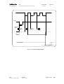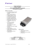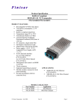
1
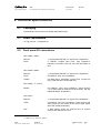
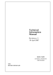
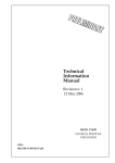
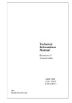
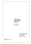
Technical
Information
Manual
Revision n. 0
5 November 2003
MOD. N1145
QUAD SCALER
AND PRESET
COUNTER/TIMER
NPO:
00115/01:N1145.MUTx/00
CAEN will repair or replace any product within the guarantee period if the Guarantor declares
that the product is defective due to workmanship or materials and has not been caused by
mishandling, negligence on behalf of the User, accident or any abnormal conditions or
operations.
CAEN declines all responsibility for damages or
injuries caused by an improper use of the Modules due
to negligence on behalf of the User. It is strongly
recommended to read thoroughly the CAEN User's
Manual before any kind of operation.
CAEN reserves the right to change partially or entirely the contents of this Manual at any time
and without giving any notice.
Document type:
User's Manual (MUT)
Title:
N1145 Quad Scaler and Preset Counter/Timer
Revision date:
05/11/2003
Revision:
0
TABLE OF CONTENTS
1.
2.
3.
4.
GENERAL DESCRIPTION.........................................................................................................................4
1.1.
OVERVIEW ...............................................................................................................................................4
1.2.
FRONT PANEL ...........................................................................................................................................5
TECHNICAL SPECIFICATIONS ..............................................................................................................6
2.1.
PACKAGING ..............................................................................................................................................6
2.1.
POWER REQUIREMENTS ............................................................................................................................6
2.2.
FRONT PANEL I/O CONNECTIONS..............................................................................................................6
2.3.
FRONT PANEL SWITCHES ..........................................................................................................................7
2.4.
TECHNICAL SPECIFICATION TABLE ...........................................................................................................8
PRINCIPLES OF OPERATION .................................................................................................................9
3.1.
SECTIONS 1 TO 4 .......................................................................................................................................9
3.2.
SECTION 5 ................................................................................................................................................9
OPERATING MODES ...............................................................................................................................12
4.1.
GATED UP-COUNTING .............................................................................................................................12
4.2.
16- OR 24- DIGIT UP-COUNTING ............................................................................................................12
4.3.
FREQUENCY MEASUREMENTS .................................................................................................................12
4.4.
DIVIDER .................................................................................................................................................13
4.5.
DELAY UNIT ...........................................................................................................................................13
4.6.
MEASUREMENT ACCURACY....................................................................................................................13
LIST OF FIGURES
FIG. 1.1 – MOD. N1145 FRONT PANEL ....................................................................................................................5
FIG. 3.1 – SECTION 5 TIMING DIAGRAM ................................................................................................................11
LIST OF TABLES
TABLE 2.1: MOD. N1145 TECHNICAL FEATURES.....................................................................................................8
NPO:
00115/01:N1145.MUTx/00
Filename:
n1145_rev0.doc
Number of pages:
14
Page:
3
Document type:
User's Manual (MUT)
Title:
N1145 Quad Scaler and Preset Counter/Timer
Revision date:
05/11/2003
Revision:
0
1. General description
1.1. Overview
CAEN Mod. N1145 is a double unit NIM module that includes four independent 8-digit
up-counters, plus a fifth 7-digit down-counter that can be used either as a preset counter
or as timer.
The counters can perform different operations and can be variously interconnected,
thereby making the module a flexible and powerful tool for several applications involving
time, frequency and ratio measurements.
All counters can accept either TTL or NIM inputs. All control and output signals are
standard NIM. The maximum input frequency is 250 MHz and the minimum pulse width is
2 ns for the up-counters, and respectively 80 MHz and 3 ns for the down-counter.
All input and output connectors as well as all the control switches are located on the front
panel. All input and output connectors are LEMO 00 type.
NPO:
00115/01:N1145.MUTx/00
Filename:
n1145_rev0.doc
Number of pages:
14
Page:
4
Document type:
User's Manual (MUT)
Title:
N1145 Quad Scaler and Preset Counter/Timer
Revision date:
05/11/2003
Revision:
0
1.2. Front panel
Mod.
N 1145
QUADQUAD
SCALER
AND AND
SCALER
PRESET COUNTER / TIMER
PRESET COUNTER-TIMER
IN
INPUT
CONNECTOR
GATE
MODE SELECTION
SWITCH
NORMAL
GATE
GATE BRIDGED
CONNECTORS
CH 1
GT+CLR
IN
INPUT
CONNECTOR
GATE
CARRY
MODE SELECTION
SWITCH
NORMAL
GATE
GATE
CONNECTOR
CH 2
GT+CLR
CARRY
CONNECTOR
IN
INPUT
CONNECTOR
GATE
MODE SELECTION
SWITCH
NORMAL
GATE
GATE BRIDGED
CONNECTORS
CH 3
GT+CLR
IN
INPUT
CONNECTOR
GATE
CARRY
GATE
CONNECTOR
NORMAL
GATE
CH 4
MODE SELECTION
SWITCH
GT+CLR
CARRY
CONNECTOR
RESET
CH 1
CH 2
CH 3
CH 4
RESET
CONNECTOR
RESET
PUSHBUTTONS
IN
INPUT
CONNECTOR
END MARKER
OUT
SGL
SGL
OUTPUT
CONNECTOR
SINGLE/REPEAT
SWITCH
RPT
REP
COUNTER
END MARKER
CONNECTOR
1 us
LOAD
SOURCE SELECT
SWITCH
LOAD
CONNECTOR
1 ms
TIMER
FREQUENCY
SELECT SWITCH
LOAD
PUSHBUTTON
-
-
-
-
-
-
-
+
+
+
+
+
+
+
THUMB
SWITCHES
Fig. 1.1 – Mod. N1145 Front Panel
NPO:
00115/01:N1145.MUTx/00
Filename:
n1145_rev0.doc
Number of pages:
14
Page:
5
Document type:
User's Manual (MUT)
Title:
N1145 Quad Scaler and Preset Counter/Timer
Revision date:
05/11/2003
Revision:
0
2. Technical specifications
2.1.
Packaging
The Model N1145 is housed in a double width NIM module.
2.1. Power requirements
+6 V @ 700 mA; −6 V @ 900 mA
2.2. Front panel I/O connections
SECTIONS 1 AND 3
INPUTS
1, accepts both NIM and TTL signals, 50 Ω impedance.
GATE
2, NIM/TTL bridged input ports, high impedance,
internally connected. Free port must be terminated on
50 Ω
SECTIONS 2 AND 4
INPUTS
1, accepts both NIM and TTL signals, 50 Ω impedance.
GATE
one NIM/TTL input, 50 Ω impedance.
CARRY
one NIM output. Generates a pulse when counter has
fully cycled (transition 99,999,999 to 0).
SECTIONS 1, 2, 3 and 4
one NIM/TTL input, 50 Ω impedance, clears sections
1 to 4. Same effect is obtained, for each section, with the
individual RESET pushbuttons.
RESET
SECTION 5
INPUTS
1, accepts both NIM and TTL signals, 50 Ω impedance.
LOAD
one NIM/TTL input, 50 Ω impedance. Loads counter with
value preset on the thumb wheel switch digits (same
effect with LOAD pushbutton).
OUT
2, NIM outputs, these are true(∗)as long as counter
contents are different from zero.
(∗) NIM level 1=-800 mV=TRUE
NPO:
00115/01:N1145.MUTx/00
Filename:
n1145_rev0.doc
Number of pages:
14
Page:
6
Document type:
User's Manual (MUT)
Title:
N1145 Quad Scaler and Preset Counter/Timer
END MARKER
Revision date:
05/11/2003
Revision:
0
one NIM output, a pulse generated when the counter
contents become zero. Pulse width is adjusted with
trimmer between 50 ns and 1 µs.
All connectors are LEMO 00 type.
2.3. Front panel switches
MODE SELECTION SWITCHES (Section 1 ÷ 4)
Function: they allow to select the operating mode (see § 3.1).
RESET PUSHBUTTONS (Section 1 ÷ 4)
Function: they allow to clear the relevant section (see § 3.1).
SOURCE SELECTION SWITCH (Section 5)
Function: it allows to select the operating mode (see § 3.2).
SINGLE/REPEAT SWITCH (Section 5)
Function: it allows to select the counter cycling (see § 3.2).
FREQUENCY SELECTION SWITCH (Section 5)
Function: it allows to select the internal clock frequency (see § 3.2).
LOAD PUSHBUTTON (Section 5)
Function: it allows to load the thumb switches value (see § 3.2).
THUMB SWITCHES (Section 5)
Function: they allow to set the counter/timer datum (see § 3.2).
NPO:
00115/01:N1145.MUTx/00
Filename:
n1145_rev0.doc
Number of pages:
14
Page:
7
Document type:
User's Manual (MUT)
Title:
N1145 Quad Scaler and Preset Counter/Timer
Revision date:
05/11/2003
Revision:
0
2.4. Technical specification table
Table 2.1: Mod. N1145 Technical Features
Packaging
Two units wide NIM module
1 NIM/TTL level input per section, 50 Ω impedance;
min. FWHM: 2 ns1 (sections 1 ÷ 4), 3 ns (section 5)
Inputs
Control
inputs
Comm. Reset
1 NIM/TTL input, 50 Ω impedance; clears sections from 1 to 4,
min. FWHM: 3 ns
Gate
Section 1 and 3: 2 bridged high-impedance NIM/TTL inputs
Section 2 and 4: 50 Ω impedance NIM/TTL input
Load
1 NIM/TTL input, loads counter with value set on thumb-wheel
switches, min. FWHM: 3 ns
std. NIM level; two sections can be cascaded by feeding first
Carry
CARRY into the input of the second section, thereby making a
(Section 2 and 4)
16-digit counter
Control
outputs
Max.
frequency
End marker
1 NIM output; a pulse is generated when the counter reaches
zero. Pulse width can be adjusted by turning the front panel
trimmer (50 ns to 1 µs)
Out
2 NIM outputs; are true as long as counter's value differs from
zero
Sections 1 to 4
Section 5
1
250 MHz
80 MHz
FWHM is 2.2 ns when GATE + CLEAR mode (see § 3.1) is used.
NPO:
00115/01:N1145.MUTx/00
Filename:
n1145_rev0.doc
Number of pages:
14
Page:
8
Document type:
User's Manual (MUT)
Title:
N1145 Quad Scaler and Preset Counter/Timer
Revision date:
05/11/2003
Revision:
0
3. Principles of operation
3.1. Sections 1 to 4
The 8-digit up-counters can operate in three distinct modes, which are:
NORMAL
Free running. The counter is incremented by the input pulses.
GATE
The counter is incremented by input pulses only if the GATE
input is true.
GATE + CLEAR
Same as GATE mode, but the leading edge of the GATE input
clears the counter.
The modes are manually selectable, for each section, by the relevant switches (see §
2.3) on the front panel. The up-counters are reset to zero, either manually (individually for
each section) by acting on the RESET pushbuttons, or electrically (common to all
sections) by means of a NIM/TTL pulse on the RESET input.
Sections 1 and 3 have two NIM/TTL high impedance GATE bridged inputs which are
internally connected; a NIM/TTL input must be terminated with a 50 Ω impedance at the
other port.
Sections 2 and 4 have one 50 Ω GATE NIM/TTL input and one CARRY NIM output. The
CARRY output generates a NIM pulse when the counter has fully cycled (transition from
max counter value to zero). This can be used to extend the counters' range by cascading
sections, as shown later.
3.2. Section 5
The fifth counter is a 7-digit counter that can operate as a PRESETTABLE DOWNCOUNTER or as a TIMER. Either mode is selected by the manual SOURCE SELECT
switch (labelled COUNTER/TIMER).
In COUNTER mode
the counter is decremented by the external (NIM or TTL) input
pulses.
In TIMER mode
the counter is decremented by an internal clock, regardless the
input pulses. The frequency is selectable by acting on the
TIMER switch and can be set to 1 KHz (1 ms) or to 1 MHz
(1 µs).
In either mode, the counter must be initally preset to the desired value by acting on the
Thumb wheel switches and then by loading the datum either manually with the LOAD
pushbutton or electrically with the LOAD NIM/TTL pulse2. At the trailing edge of the first
2
Any value can be loaded except Zero, which is not recognised by the module.
NPO:
00115/01:N1145.MUTx/00
Filename:
n1145_rev0.doc
Number of pages:
14
Page:
9
Document type:
User's Manual (MUT)
Title:
N1145 Quad Scaler and Preset Counter/Timer
Revision date:
05/11/2003
Revision:
0
input pulse the OUT ports become true. The counter is then decremented by the input
pulses until zero is reached. At the trailing edge of the last input pulse:
the OUT outputs are reset to FALSE (0 V).
the END MARKER output generates a NIM pulse whose length can be adjusted between
50 ns and 1 µs by acting on the trimmer next to the END MARKER connector; this signal
is retriggerable, thus it can be extended while active by another completed cycle. If the
END MARKER is used for retriggering purposes (it is sent to the LOAD connector), a
delay larger than the END MARKER duration is required between these connectors.
This arrangement allows direct use of the OUT ports as GATE inputs to the counters of
section 1 to 4.
CYCLING of Section 5 is controlled by the SINGLE/REPEAT switch, which is labelled
SGL/REP.
In SINGLE mode
the selected function (PRESET COUNTER or TIMER) is
performed only once, until zero is reached. In order to restart
the counter, a new load operation is required. Actually, when
using the LOAD button, the counter can be restarted even
BEFORE zero is reached. The LOAD NIM/TTL signal is
disabled during counting. After a LOAD via pushbutton, the unit
requires 80 ns at least before accepting LOAD pulses, even if
the counter is already zero and thus the cycle completed.
In REPEAT mode
a few seconds after zero is reached the counter re-triggers
itself automatically, by performing an automatic LOAD, and a
new cycle is restarted. The automatic LOAD takes place every
2 seconds after every cycle end. This procedure is repeated
indefinitely; anyway, the LOAD button allows to restart the
counter at any time. The LOAD NIM/TTL is always useless in
REPEAT mode.
Note that by connecting the END MARKER output to the LOAD input the counter is
cycled without the time delay of the REPEAT mode.
Important Note: one or more of the following operations may lead the Section 5 to an
incorrect operation:
− The use of an external clock with frequency larger than 80 MHz
− The use of an external clock with pulse width shorter than 3 ns
− The variation during the counter operation of the external clock frequency
− The switching from internal clock to external or vice versa
In any case the counter normal operation is recovered by performing a manual/electrical
LOAD.
NPO:
00115/01:N1145.MUTx/00
Filename:
n1145_rev0.doc
Number of pages:
14
Page:
10
Document type:
User's Manual (MUT)
Title:
N1145 Quad Scaler and Preset Counter/Timer
Revision date:
05/11/2003
Revision:
0
NIM INPUT
LOAD
DISPLAY
DATA
0
3 ns
min
3
2
1
0
OUT
END MARKER
Trimmer adjustable
Fig. 3.1 – Section 5 Timing Diagram
NPO:
00115/01:N1145.MUTx/00
Filename:
n1145_rev0.doc
Number of pages:
14
Page:
11
Document type:
User's Manual (MUT)
Title:
N1145 Quad Scaler and Preset Counter/Timer
Revision date:
05/11/2003
Revision:
0
4. Operating modes
4.1. Gated up-counting
When in NORMAL MODE, the counters (sections 1 to 4) do not require a GATE input.
However, when in GATE (or GATE+CLEAR) mode, a NIM/TTL signal must be supplied
at the GATE input of each counter used. NOTE: when using NIM input signals, this signal
has to be terminated with a 50 Ω impedance at the other GATE bridged input, on
sections 1 or 3.
A single GATE signal can be sent in parallel, to two channels via cables; if the last
section is either 2 or 4 then this also provides the correct 50 Ω cable termination. For
example, sections 1 and 2 can share a GATE by feeding the external GATE signal to the
GATE input of section 1 and then connecting a cable between the other GATE output of
section 1 to the GATE input of section 2, which has a 50 Ω impedance. It is also possible
to connect three sections (for instance #1 with #3, and then #3 with #2 or #4) via cables,
in order to send them a single external GATE input.
The OUT signal of section 5 can be used as the GATE input to the counters. The double
OUT connector permits parallel GATE feeding of all four sections, as described above.
4.2. 16- or 24- Digit Up-Counting
It is possible to increase the up-counting range to 16 or 24 digits by using the CARRY
outputs of sections 2 and 4.
For instance, 16-digit up-counting is obtained by connecting the CARRY output of
section 2 to the input of section 1. When the counter of section 2 has fully cycled
(transition 99,999,999 to zero) the CARRY output supplies a NIM input pulse to section 1,
and so on. Thus section 1 will show the most significant digits, and section 2 the least
significant digits of the counting operation.
Similarly, for 24-digit up-counting, the CARRY output of section 2 may be connected to
the input of section 4; the CARRY output of section 4 may then be fed to the input of
section 1 or 3.
4.3. Frequency measurements
This is a way of making relative frequency measurements.
By using section 5 in TIMER MODE, it is possible to make a frequency measurement.
For that purpose:
•
select the clock rate:
NPO:
00115/01:N1145.MUTx/00
Filename:
n1145_rev0.doc
ƒ=1/τ
Number of pages:
14
Page:
12
Document type:
User's Manual (MUT)
Title:
N1145 Quad Scaler and Preset Counter/Timer
with the TIMER switch:
•
Revision date:
05/11/2003
Revision:
0
(τ=1 μs or 1 ms)
select a value N (for instance a power of 10) with the thumb wheel switches. The
measurement time is then: Ti=Nτ
• use the OUT signal as the GATE input to the selected section 1 to 4 Counter(s),
operating in GATE+CLEAR mode.
The external input frequency is then given by:
ƒi=(Mc)/(Nτ)
where Mc is the number of pulses received by the Counter while GATE is active.
4.4. Divider
Section 5 can also be used as a divider of an external input sequence. For that purpose:
• connect the END MARKER output to the LOAD input.
• Select the input / output ratio R by setting the thumb wheel switches.
• Connect the external input at the section 5 input port and pick the NIM output from the
OUT ports, which is a pulse generated every R pulses at the input.
4.5. Delay unit
Section 5 can also be used to generate a delayed pulse (at the END MARKER output) or
transition (at the OUT ports).
An absolute delay can be obtained with section 5 in TIMER Mode. The duration of the
delay is Td=Nτ (actually the time interval between the LOAD signal leading edge and the
leading edge of the END MARKER) where N is the preset value on the Thumb wheel
switch display, and τ is the internal clock period. The time delay is the elapsed time
between the time of the leading edge at the LOAD input and leading edge either at the
END MARKER output. See the next section for accuracy. With the counter in COUNTER
Mode, a relative delay (in terms of number of pulses) can be obtained between the
NIM/TTL input and the END MARKER, after the preset number of input pulses have been
counted.
4.6. Measurement accuracy
For the previous applications, it is important to remember that with any measurement
made with a counter on a periodic waveform there is always an intrinsic uncertainty of
one pulse. This is due to the fact that, depending on the position of the start of the
measurement window with respect to the period of the waveform, one pulse may or may
not be totally included, and thus counted for. This also applies to the uncertainty of the
selection of the reference time window.
NPO:
00115/01:N1145.MUTx/00
Filename:
n1145_rev0.doc
Number of pages:
14
Page:
13
Document type:
User's Manual (MUT)
Title:
N1145 Quad Scaler and Preset Counter/Timer
Revision date:
05/11/2003
Revision:
0
The uncertainty of the measurement of an absolute time delay is therefore equal to the
clock period.
For frequency measurements it is:
Δƒi=ƒmax−ƒmin=(Mc)/(Nτ)−(Mc-1)/(Nτ)=1/(Nτ)
where Δƒi is the absolute frequency uncertainty. The relative frequency uncertainty is
then:
Δƒi=1−(Mc)
and since for a given (constant) frequency Mc(=Nƒτ) is proportional to N, the percent
accuracy is increased by increasing N.
NPO:
00115/01:N1145.MUTx/00
Filename:
n1145_rev0.doc
Number of pages:
14
Page:
14