1
Wisen Innovation Technical Doc. No.2003
2)
(Notice
WISENMESHNET® VW Interface Node User Manual
A.
The braid screen is connected to the box;
B.
The 4 coils are connected to the unit signal terminals;
C.
The 1 drain wire is connected to the electrical circuit ground.
Reputable manufacturers.
: Wisen can always recommend an updated EMC solution and some suitable manufacturers around the
world to our customers. Please contact Wisen for further information).
5.3.
Deployment Procedures
1)
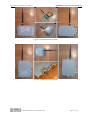
Open the box: Take the node out of the package and open its lid;
2)
Insert Battery: By default, a node does not contain a D-Cell battery. Therefore the battery needs to be inserted.
Notice
: +ve and –ve orientation must be correct, otherwise, the internal circuit may be damaged; As our
VW Interface Nodes has more than one battery installed, special attention must be paid to avoid shorting the
battery by the battery holder. Notice
3)
: batteries are inserted “Head to Head” in the holder.
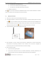
Antenna Installation: screw the antenna tightly onto the node;
Figure 6. Mesh Antenna
4) Sensor Installation: To ensure a customer chosen VW sensor is deployed onto a structure correctly, please
strictly follow the corresponding manufacturer sensor instructions. Once a VW sensor is deployed and
pre-tensioned, please use a handheld readout device to confirm the readings.
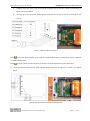
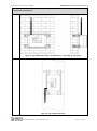
5) Sensor connections to Node:
A.
Strip the cable sleeving back by 8mm.
B.
The 5 wires from the cable are VW+, VW-, Thermistor (Temperature)+, Thermistor (Temperature)- and
Ground. Please refer to the sensor datasheet to identify the purpose of the stripped wires.
www.wiseninnovation.co.uk / www.wisencn.com
Page - 10 - of 20