1
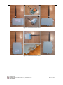
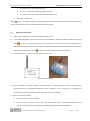
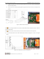
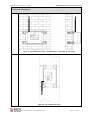
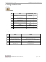
Wisen Innovation Technical Doc. No.2003 WISENMESHNET® VW Interface Node User Manual WISENMESHNET® Vibrating Wire (VW) Interface Node (1 / 4 / 8-Channel) User Manual Wisen Innovation Ltd July 2014 www.wiseninnovation.co.uk / www.wisencn.com Page - 1 - of 20 Wisen Innovation Technical Doc. No.2003 WISENMESHNET® VW Interface Node User Manual Revision History and Clarification Rev. Issue Date Revisions Written By Revised By V5.0 20/06/2014 1 Issue st Tony Shi Yan Wu V6.0 28/07/2014 2 Issue nd Yan Wu Brian Jones V7.0 03/08/2014 3 Issue rd Yan Wu Ian Wassell V8.0 06/08/2014 4 Issue th Yan Wu Ian Wassell Document Definition: It defines the specifications (introduction, usage and maintenance method) of the VW interface node, which is ® one of the key components in WISENMESHNET Low Power, Intelligent, Wireless Sensor Network system. Scope: Customer Site Project Managers and Engineers, Wisen Services Engineers. Notice : ® This documentation provides the basic instructions about the WISENMESHNET VW Interface node. Any further information can be requested by the customers. www.wiseninnovation.co.uk / www.wisencn.com Page - 2 - of 20 Wisen Innovation Technical Doc. No.2003 WISENMESHNET® VW Interface Node User Manual Table of Contents 1. Product Introduction ............................................................................................................... - 4 2. System Structure Layout.......................................................................................................... - 6 3. Features ................................................................................................................................... - 7 4. VW Interface Node Terminologies .......................................................................................... - 8 5. Operation Procedures.............................................................................................................. - 9 5.1.System Deployment Notifications: .............................................................................. - 9 5.2. Choosing your VW Sensors ......................................................................................... - 9 5.3. Deployment Procedures ........................................................................................... - 10 5.4.VW Interface Node Mounting Options ...................................................................... - 12 6. General Maintenance and Notification ................................................................................. - 16 7. Package and Accessories ....................................................................................................... - 18 8. Safety and Warning ............................................................................................................... - 19 9. Contact .................................................................................................................................. - 20 - www.wiseninnovation.co.uk / www.wisencn.com Page - 3 - of 20 Wisen Innovation Technical Doc. No.2003 WISENMESHNET® VW Interface Node User Manual 1. Product Introduction ® The WISENMESHNET Vibrating Wire (VW) Interface Node is one of the key products in our ® ® patented WISENMESHNET geotechnical safety monitoring system. Working together with the WISENMESHNET gateway product and our customers VW type sensors, it intelligently delivers the real-time VW derived deformation of the structure to the information centre. ® ® The WISENMESHNET VW Interface Node operates using our core technology, i.e., the WISENMESHNET Low Power, Intelligent, Wireless Sensor Network protocol, together with its internal high precision frequency sampling module and power unit. This interface node is compatible with conventional geotechnical vibrating wire type sensors measuring in the range from 400 to 6000Hz. This product satisfies the three fundamental identities of the system: A. Network Life Span: to maximise battery life across the mesh network as a whole; B. Network Data Arrival Rate: to minimise data packet loss; C. Single Node Environmental Coverage: to maximise radio coverage. Our product has IP66 and CE marking and is designed to work in a tough environment. It is small in size, reliable in performance, easy for maintenance, has high precision during sampling, and has strong immunity to radio-interference. Figure 1. The 1-VW Overview in Photos. www.wiseninnovation.co.uk / www.wisencn.com Page - 4 - of 20 Wisen Innovation Technical Doc. No.2003 WISENMESHNET® VW Interface Node User Manual Figure 2. The 4-VW Overview in Photos. Figure 3. The 8-VW Overview in Photos. www.wiseninnovation.co.uk / www.wisencn.com Page - 5 - of 20 Wisen Innovation Technical Doc. No.2003 WISENMESHNET® VW Interface Node User Manual 2. System Structure Layout www.wiseninnovation.co.uk / www.wisencn.com Page - 6 - of 20 Wisen Innovation Technical Doc. No.2003 WISENMESHNET® VW Interface Node User Manual 3. Features ® WISENMESHNET 1 / 4 / 8-Channel Vibrating Wire (VW) Interface Nodes @ Typ. 25℃ Basics Power Supply Qty. x 2 for 1/4-Channel; Qty. x 4 for 8-Channel (3.6V D-Cell 32650) Stop/Min Voltage 2.1VDC Battery Connection Standard Metal Battery Holder Working Current (DC) Max. 190mA (Typ.) Operating Temperature -40 to 80℃ Storage 300 Messages during Meshing LxWxH 160x100x65mm 1/4-Channel; 180x140x60mm 8-Channel Weight 1.0kg for 1/4-Channel; 1.5kg for 8-Channel Fixing Bracket 250x35mm Din Rail of Slots of 15x6mm (Qty. 2) IP Rating IP66 Certificate CE ® Interface WISENMESHNET Protocol@250kbps No. of Inputs 1 / 4 / 8 VW Sensors Sensor Connection WAGO Internal Terminal Plugs Inspection Period Every 2 Years Inspection Method Manufacturer Calibration Main Sensor (Excluded) Vibrating Wire Type Parameter Resonant Frequency (Hz) Measurement Range 400Hz to 6000Hz Accuracy 0.02% of Full Scale (Hz) No. of Channels 1 / 4 / 8 Channels Resolution 0.1Hz Auxiliary Sensor Temperature Thermistor Range 3kΩ to 17kΩ Accuracy 3Ω Antenna-2.4GHz Omni-directional 5dBi (20cm) or Customised Antenna Connect SMA (Female) Protocol WISENMESHNET® Protocol / 802.15.4 Compatible Frequency Band 2.405GHz~2.480GHz (16 Channels) Sensor Wireless Mesh Interface Radio Parameter Transmit Power < 1.5dBm 20dBm (Customised) Receive Sensitivity -103dBm -108dBm (Customised) ® WISENMESHNET - The 3 Fundamental Identities Network Life Span Network Data Arrival Rate Single Node Environmental Coverage >= 36 months @ Tx power = ~0dBm (typical, 0.5dBm), antenna type 5dBi (omni-directional) @ sampling rate = 10mins Into WISENMESHNET® greater than 99.5% i. Light concrete indoor environment ≥ Approx. 900 square meters ii. Underground tunnel environment ≤ Approx. ±200m (tunnel diameter = 3m, Tx, Rx antenna distance to the wall = 10cm) www.wiseninnovation.co.uk / www.wisencn.com Page - 7 - of 20 Wisen Innovation Technical Doc. No.2003 WISENMESHNET® VW Interface Node User Manual 4. VW Interface Node Terminologies Notice : In any Wisen battery powered product, unless specified, the batteries are inserted “Head to Head”. Figure 4. VW Interface Node Internal Configuration Terminologies (Left: the 1-VW; Right: the 4-VW). Figure 5. The 8-VW Interface Node Internal Configuration Terminologies. www.wiseninnovation.co.uk / www.wisencn.com Page - 8 - of 20 Wisen Innovation Technical Doc. No.2003 WISENMESHNET® VW Interface Node User Manual 5. Operation Procedures 5.1.System Deployment Notifications: 1) Location: The deployment location of a VW Interface Node is usually determined by the required monitoring or inspection location; 2) Before any VW Interface Node is switched on, two tasks will need to be carried out: A. Unlike the Tilt Node which has a MEM dual-axis tilt sensor embedded in the node, the VW sensors chosen by the customer, e.g., VW crackmeter, VW settlement gauge, VW strain gauge, etc, must be connected to the VW Interface Node; B. A gateway must be deployed, powered on and proven to be working properly. Otherwise, the nodes will need to be switched off, then switched on again after a gateway is switched on. So simply speaking, the rules to follow to correctly deploy a WISENMESHNET system are: 1) Gateway first; 2) then nearby nodes with the VW sensors connected; 3) then further nodes with the VW sensors connected. 3) During deployment, the Serial Number, i.e., SN of a node and the orientation of the VW sensors deployed against their site references must be reorded; 4) The connections between a customer chosen VW sensor and a Wisen VW Interface Node must strictly follow the rules stated in the relevant document; 5) All the VW Interface Node should be oriented upwards, i.e., 5.2. , or . Choosing your VW Sensors Most problems encountered during monitoring will be caused by the quality of VW sensors including the cables, especially in environments experiencing strong Electromagnetic (EM) interference, such as national grid tunnels. The essential requirements when choosing a VW sensor are listed below: 1) The sensor cable: insulation sleeve, braid screen, 4 coils, one drain wire, where: www.wiseninnovation.co.uk / www.wisencn.com Page - 9 - of 20 Wisen Innovation Technical Doc. No.2003 2) (Notice WISENMESHNET® VW Interface Node User Manual A. The braid screen is connected to the box; B. The 4 coils are connected to the unit signal terminals; C. The 1 drain wire is connected to the electrical circuit ground. Reputable manufacturers. : Wisen can always recommend an updated EMC solution and some suitable manufacturers around the world to our customers. Please contact Wisen for further information). 5.3. Deployment Procedures 1) Open the box: Take the node out of the package and open its lid; 2) Insert Battery: By default, a node does not contain a D-Cell battery. Therefore the battery needs to be inserted. Notice : +ve and –ve orientation must be correct, otherwise, the internal circuit may be damaged; As our VW Interface Nodes has more than one battery installed, special attention must be paid to avoid shorting the battery by the battery holder. Notice 3) : batteries are inserted “Head to Head” in the holder. Antenna Installation: screw the antenna tightly onto the node; Figure 6. Mesh Antenna 4) Sensor Installation: To ensure a customer chosen VW sensor is deployed onto a structure correctly, please strictly follow the corresponding manufacturer sensor instructions. Once a VW sensor is deployed and pre-tensioned, please use a handheld readout device to confirm the readings. 5) Sensor connections to Node: A. Strip the cable sleeving back by 8mm. B. The 5 wires from the cable are VW+, VW-, Thermistor (Temperature)+, Thermistor (Temperature)- and Ground. Please refer to the sensor datasheet to identify the purpose of the stripped wires. www.wiseninnovation.co.uk / www.wisencn.com Page - 10 - of 20 Wisen Innovation Technical Doc. No.2003 C. WISENMESHNET® VW Interface Node User Manual Untighten the gland cover, insert cable through the gland, then connect the 5 wires correspondingly as shown in the Figure below. D. Once the wires are connected, please tighten the gland cover firmly to ensure its IP rating on that channel. Figure 7. VW Sensor Wire Connections Notice 1: The cable gland diameter of the 1-VW and 4-VW Interface Nodes are both 8mm, while it is 6mm for the 8-VW Interface Node. Notice 2: All the 5 wires must be connected, to minimise electrical interference and loss of precision. 6) The 4-VW Interface Node and the 8-VW Interface Node Connection Arrangement is shown in the figures below. Figure 8. The 4-VW Sensors Connection Arrangements. www.wiseninnovation.co.uk / www.wisencn.com Page - 11 - of 20 Wisen Innovation Technical Doc. No.2003 WISENMESHNET® VW Interface Node User Manual Figure 9. The 8-VW Sensors Connection Arrangements. Notice : For the 4-VW and 8-VW Interface Nodes, if some of the channels are not used, please seal the cable gland properly. 7) Power On: once all the VW sensors are connected, press the ON/OFF button. Now you should be able to see 3 LEDs flashing 3 times, that means the node is on. Then switch off the node to save power if the gateway is off; ® 8) To validate the sensor data, and to see that it works, please refer to the << WISENMESHNET System Evaluation User Guide >>. Notice ! To properly deploy a node, you must firstly have a Smart Gateway turned on before a node is powered on. Otherwise, a powered-on isolated node will consume most of its power executing its mesh network searching mode. Therefore battery life is shortened significantly. 5.4.VW Interface Node Mounting Options Depending on the installation surface, the VW Interface Nodes can be deployed using different methods: 1) Surface Fixing using Din Rails Step 1: Cap-Hex-Head Screw M6x14 – firmly screw Din Rails to the back of the node box; Step 2: Anchor Bolt M6x70 (Drill size of M10) – firmly bolt Din Rails onto the flat surface. 2) Column Fixing using Metal Releasable Cable Ties. Please refer to the figures below: www.wiseninnovation.co.uk / www.wisencn.com Page - 12 - of 20 Wisen Innovation Technical Doc. No.2003 WISENMESHNET® VW Interface Node User Manual 1-Channel VW Interface Node Figure 10. The 1-VW Surface Fixing – Dual Din Rails (L – Front View; R – Side View). Figure 11. The 1-VW Column Fixing – Releasable Cable Tie. www.wiseninnovation.co.uk / www.wisencn.com Page - 13 - of 20 Wisen Innovation Technical Doc. No.2003 WISENMESHNET® VW Interface Node User Manual 4-Channel VW Interface Node Figure 12. The 4-VW Surface Fixing – Dual Din Rails (L – Front View; R – Side View). Figure 13. The 4-VW Column Fixing. www.wiseninnovation.co.uk / www.wisencn.com Page - 14 - of 20 Wisen Innovation Technical Doc. No.2003 WISENMESHNET® VW Interface Node User Manual 8-Channel VW Interface Node Figure 14. The 8-VW Surface Fixing – Dual Din Rails (L – Front View; R – Side View). Figure 15. The 8-VW Surface Fixing – Single Din Rail (L – Front View; R – Side View). www.wiseninnovation.co.uk / www.wisencn.com Page - 15 - of 20 Wisen Innovation Technical Doc. No.2003 WISENMESHNET® VW Interface Node User Manual Figure 16. The 8-VW Column Fixing. 6. General Maintenance and Notification 1) Once VW Node is installed in the field, please minimise any man-made disturbance so that data quality can be maintained; 2) Radio communication will be impaired if the antenna is covered by metal or very moist soil material; 3) Due to the discharge characteristics of the recommended battery, a battery replacement should be carried out when a node reported voltage reaches 2.7V, at which point you have approximately 3 weeks to change the battery; 4) Our product will use all the possible capacity in a battery down to a stop (minimum) voltage, which has been specified in the Features table. When this occurs, our WISENMESHNET protocol will send you a warning then it will enter a deep sleep mode until a new battery is installed; www.wiseninnovation.co.uk / www.wisencn.com Page - 16 - of 20 Wisen Innovation Technical Doc. No.2003 WISENMESHNET® VW Interface Node User Manual 5) If the data from nodes are showing unexpected results or are not being sent back to the Wisen gateway, then please carry out investigation using the following two stage procedure: A. Remote Inspection of historical data, to identify the following: a) Whether the heart-beat message has been sent back successfully at each time interval; b) Whether the battery voltage is too low, if yes, please change the battery unit; c) Whether the signal strength has become significantly weaker than it was previously. If yes, please check the antenna has been screwed on firmly. B. On-site Inspection: If all the above are good, please arrange an on-site inspection to check: a) Whether the VW Node has visible external damage; b) Check the box lid to see if it is firmly tightened; c) Whether the antenna is bent or damaged and that the node is not blocked by new construction, e.g., hoardings; d) When it is possible, check that the signal strength is normal by using a spectrum analyser; e) Open the lid, to see whether the battery is firmly attached to its holder; f) Use a multi-meter to measure the battery voltage. If it is below the stop (minimum) voltage, replace the battery. g) Notices Make sure the 5 wires are connected properly, if necessary, please disconnect the wires to inspect. : i. Case One: If any change has been made from the list above, please inspect the data at the remote server; ii. Case Two: If all the actions from the list above have not cured the problem, please contact Wisen. We will be happy to help. www.wiseninnovation.co.uk / www.wisencn.com Page - 17 - of 20 Wisen Innovation Technical Doc. No.2003 WISENMESHNET® VW Interface Node User Manual 7. Package and Accessories Standard: No. Items 1 WISENMESHNET VW Interface Node (1, ® Dimension (mm) Qty. 160x100x60 1 4, or 8-Channel) 2 User Manual - 1 3 Inspection Report - 1 4 2.4GHz 5dBi Omni-directional Antenna 200 1 5 Din Rail 250x35 2 6 Cap-Hex-Head Screw M6x14 4 7 Anchor Bolt M6x70 4 Optional/Customer Preparation: No. Items Purpose 1 Battery For the node 2 M6 Anchor Bolt Spanner Bolts to the mounting surface 3 M6 Cap-Hex-Head Screwdriver Screws between din rail and the back of the node box 4 M3 Cap-Hex-Head Screwdriver Screws on the lid 5 Metal Cable Tie For special mounting www.wiseninnovation.co.uk / www.wisencn.com Page - 18 - of 20 Wisen Innovation Technical Doc. No.2003 WISENMESHNET® VW Interface Node User Manual 8. Safety and Warning Warning: Please read the following instructions carefully. 1)Operation Safety Before taking any action, please read all the information provided carefully, and keep the guidance documents safe; Ensure that any procedures and installations are correctly carried out. The communication cable and the case must be grounded. This product has been designed to meet a certain water-proof level. However, it becomes water vulnerable when the lid is open or if the cable gland has not been sealed properly. 2)Electric Safety To install the battery into a holder, please follow the “+” (positive) and “-” (negative) signs in any Wisen product. Wrong orientation of a battery could potential cause unit damage. Notice : The orientation of battery can vary among products. When disconnecting the battery, please take special care not to apply excessive force, otherwise the battery holder and the nearby circuitry may be damaged. 3)Warning The battery in the product has a relatively high capacity, so please take special care during storage and usage. This product must not be disassembled under any circumstances, to do so will void the warranty and may leave the product in a dangerous state; If all the above are not followed, the manufacturer cannot be held responsible for any damage and injury caused to the users. 4)Caution Danger of explosion if battery is incorrectly replaced. Replace only with the type recommended by the manufacturer. When disposing of the batteries, please contact your local authorities or dealer and ask for the correct method of disposal. www.wiseninnovation.co.uk / www.wisencn.com Page - 19 - of 20 Wisen Innovation Technical Doc. No.2003 WISENMESHNET® VW Interface Node User Manual 9. Contact - Wisen Innovation Ltd: www.wiseninnovation.co.uk - Email: [email protected] www.wiseninnovation.co.uk / www.wisencn.com Page - 20 - of 20