1
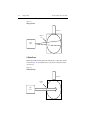
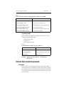
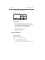
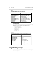
Model 2520INT Integrating Sphere
Quick Start Guide
A GREATER MEASURE OF CONFIDENCE
WARRANTY
Keithley Instruments, Inc. warrants this product to be free from defects in material and workmanship for a
period of 1 year from date of shipment.
Keithley Instruments, Inc. warrants the following items for 90 days from the date of shipment: probes, cables,
rechargeable batteries, diskettes, and documentation.
During the warranty period, we will, at our option, either repair or replace any product that proves to be defective.
To exercise this warranty, write or call your local Keithley representative, or contact Keithley headquarters in
Cleveland, Ohio. You will be given prompt assistance and return instructions. Send the product, transportation
prepaid, to the indicated service facility. Repairs will be made and the product returned, transportation prepaid.
Repaired or replaced products are warranted for the balance of the original warranty period, or at least 90 days.
LIMITATION OF WARRANTY
This warranty does not apply to defects resulting from product modification without Keithley’s express written
consent, or misuse of any product or part. This warranty also does not apply to fuses, software, non-rechargeable
batteries, damage from battery leakage, or problems arising from normal wear or failure to follow instructions.
THIS WARRANTY IS IN LIEU OF ALL OTHER WARRANTIES, EXPRESSED OR IMPLIED, INCLUDING ANY IMPLIED WARRANTY OF MERCHANTABILITY OR FITNESS FOR A PARTICULAR USE.
THE REMEDIES PROVIDED HEREIN ARE BUYER’S SOLE AND EXCLUSIVE REMEDIES.
NEITHER KEITHLEY INSTRUMENTS, INC. NOR ANY OF ITS EMPLOYEES SHALL BE LIABLE FOR
ANY DIRECT, INDIRECT, SPECIAL, INCIDENTAL OR CONSEQUENTIAL DAMAGES ARISING OUT OF
THE USE OF ITS INSTRUMENTS AND SOFTWARE EVEN IF KEITHLEY INSTRUMENTS, INC., HAS
BEEN ADVISED IN ADVANCE OF THE POSSIBILITY OF SUCH DAMAGES. SUCH EXCLUDED DAMAGES SHALL INCLUDE, BUT ARE NOT LIMITED TO: COSTS OF REMOVAL AND INSTALLATION,
LOSSES SUSTAINED AS THE RESULT OF INJURY TO ANY PERSON, OR DAMAGE TO PROPERTY.
Keithley Instruments, Inc.
28775 Aurora Road • Cleveland, Ohio 44139 • 440-248-0400 • Fax: 440-248-6168
1-888-KEITHLEY (534-8453) • www.keithley.com
Sales Offices:
Bergensesteenweg 709 • B-1600 Sint-Pieters-Leeuw • 02-363 00 40 • Fax: 02/363 00 64
Yuan Chen Xin Building, Room 705 • 12 Yumin Road, Dewai, Madian • Beijing 100029 • 8610-6202-2886 • Fax: 8610-6202-2892
Tietäjäntie 2 • 02130 Espoo • Phone: 09-54 75 08 10 • Fax: 09-25 10 51 00
3, allée des Garays • 91127 Palaiseau Cédex • 01-64 53 20 20 • Fax: 01-60 11 77 26
Landsberger Strasse 65 • 82110 Germering • 089/84 93 07-40 • Fax: 089/84 93 07-34
Unit 2 Commerce Park, Brunel Road • Theale • Berkshire RG7 4AB • 0118 929 7500 • Fax: 0118 929 7519
Flat 2B, Willocrissa • 14, Rest House Crescent • Bangalore 560 001 • 91-80-509-1320/21 • Fax: 91-80-509-1322
Viale San Gimignano, 38 • 20146 Milano • 02-48 39 16 01 • Fax: 02-48 30 22 74
New Pier Takeshiba North Tower 13F • 11-1, Kaigan 1-chome • Minato-ku, Tokyo 105-0022 • 81-3-5733-7555 • Fax: 81-3-5733-7556
2FL., URI Building • 2-14 Yangjae-Dong • Seocho-Gu, Seoul 137-888 • 82-2-574-7778 • Fax: 82-2-574-7838
Postbus 559 • 4200 AN Gorinchem • 0183-635333 • Fax: 0183-630821
c/o Regus Business Centre • Frosundaviks Allé 15, 4tr • 169 70 Solna • 08-509 04 679 • Fax: 08-655 26 10
Kriesbachstrasse 4 • 8600 Dübendorf • 01-821 94 44 • Fax: 01-820 30 81
1FL., 85 Po Ai Street • Hsinchu, Taiwan, R.O.C. • 886-3-572-9077• Fax: 886-3-572-9031
BELGIUM:
CHINA:
FINLAND:
FRANCE:
GERMANY:
GREAT BRITAIN:
INDIA:
ITALY:
JAPAN:
KOREA:
NETHERLANDS:
SWEDEN:
SWITZERLAND:
TAIWAN:
4/02
Model 2520INT Integrating Sphere
Quick Start Guide
©2002, Keithley Instruments, Inc.
All rights reserved.
Cleveland, Ohio, U.S.A.
First Printing, April 2002
Document Number: 2520INT-903-01 Rev. A
Manual Print History
The print history shown below lists the printing dates of all Revisions and Addenda created
for this manual. The Revision Level letter increases alphabetically as the manual undergoes subsequent updates. Addenda, which are released between Revisions, contain important change information that the user should incorporate immediately into the manual. Addenda are numbered
sequentially. When a new Revision is created, all Addenda associated with the previous Revision
of the manual are incorporated into the new Revision of the manual. Each new Revision includes
a revised copy of this print history page.
Revision A (Document Number 2520INT-903-01) .......................................................... April 2002
All Keithley product names are trademarks or registered trademarks of Keithley Instruments, Inc.
Other brand names are trademarks or registered trademarks of their respective holders.
Safety Precautions
The following safety precautions should be observed before using this product and any associated instrumentation. Although
some instruments and accessories would normally be used with non-hazardous voltages, there are situations where hazardous
conditions may be present.
This product is intended for use by qualified personnel who recognize shock hazards and are familiar with the safety precautions
required to avoid possible injury. Read and follow all installation, operation, and maintenance information carefully before using the product. Refer to the manual for complete product specifications.
If the product is used in a manner not specified, the protection provided by the product may be impaired.
The types of product users are:
Responsible body is the individual or group responsible for the use and maintenance of equipment, for ensuring that the equipment is operated within its specifications and operating limits, and for ensuring that operators are adequately trained.
Operators use the product for its intended function. They must be trained in electrical safety procedures and proper use of the
instrument. They must be protected from electric shock and contact with hazardous live circuits.
Maintenance personnel perform routine procedures on the product to keep it operating properly, for example, setting the line
voltage or replacing consumable materials. Maintenance procedures are described in the manual. The procedures explicitly state
if the operator may perform them. Otherwise, they should be performed only by service personnel.
Service personnel are trained to work on live circuits, and perform safe installations and repairs of products. Only properly
trained service personnel may perform installation and service procedures.
Keithley products are designed for use with electrical signals that are rated Installation Category I and Installation Category II,
as described in the International Electrotechnical Commission (IEC) Standard IEC 60664. Most measurement, control, and data
I/O signals are Installation Category I and must not be directly connected to mains voltage or to voltage sources with high transient over-voltages. Installation Category II connections require protection for high transient over-voltages often associated with
local AC mains connections. Assume all measurement, control, and data I/O connections are for connection to Category I sources unless otherwise marked or described in the Manual.
Exercise extreme caution when a shock hazard is present. Lethal voltage may be present on cable connector jacks or test fixtures.
The American National Standards Institute (ANSI) states that a shock hazard exists when voltage levels greater than 30V RMS,
42.4V peak, or 60VDC are present. A good safety practice is to expect that hazardous voltage is present in any unknown
circuit before measuring.
Operators of this product must be protected from electric shock at all times. The responsible body must ensure that operators
are prevented access and/or insulated from every connection point. In some cases, connections must be exposed to potential
human contact. Product operators in these circumstances must be trained to protect themselves from the risk of electric shock.
If the circuit is capable of operating at or above 1000 volts, no conductive part of the circuit may be exposed.
Do not connect switching cards directly to unlimited power circuits. They are intended to be used with impedance limited sources. NEVER connect switching cards directly to AC mains. When connecting sources to switching cards, install protective devices to limit fault current and voltage to the card.
Before operating an instrument, make sure the line cord is connected to a properly grounded power receptacle. Inspect the connecting cables, test leads, and jumpers for possible wear, cracks, or breaks before each use.
When installing equipment where access to the main power cord is restricted, such as rack mounting, a separate main input power disconnect device must be provided, in close proximity to the equipment and within easy reach of the operator.
For maximum safety, do not touch the product, test cables, or any other instruments while power is applied to the circuit under
test. ALWAYS remove power from the entire test system and discharge any capacitors before: connecting or disconnecting ca5/02
bles or jumpers, installing or removing switching cards, or making internal changes, such as installing or removing jumpers.
Do not touch any object that could provide a current path to the common side of the circuit under test or power line (earth) ground. Always make measurements with dry hands while standing on a dry, insulated surface capable of withstanding the voltage being measured.
The instrument and accessories must be used in accordance with its specifications and operating instructions or the safety of the
equipment may be impaired.
Do not exceed the maximum signal levels of the instruments and accessories, as defined in the specifications and operating information, and as shown on the instrument or test fixture panels, or switching card.
When fuses are used in a product, replace with same type and rating for continued protection against fire hazard.
Chassis connections must only be used as shield connections for measuring circuits, NOT as safety earth ground connections.
If you are using a test fixture, keep the lid closed while power is applied to the device under test. Safe operation requires the use
of a lid interlock.
If
The
or
!
is present, connect it to safety earth ground using the wire recommended in the user documentation.
symbol on an instrument indicates that the user should refer to the operating instructions located in the manual.
The
symbol on an instrument shows that it can source or measure 1000 volts or more, including the combined effect of
normal and common mode voltages. Use standard safety precautions to avoid personal contact with these voltages.
The WARNING heading in a manual explains dangers that might result in personal injury or death. Always read the associated
information very carefully before performing the indicated procedure.
The CAUTION heading in a manual explains hazards that could damage the instrument. Such damage may invalidate the warranty.
Instrumentation and accessories shall not be connected to humans.
Before performing any maintenance, disconnect the line cord and all test cables.
To maintain protection from electric shock and fire, replacement components in mains circuits, including the power transformer,
test leads, and input jacks, must be purchased from Keithley Instruments. Standard fuses, with applicable national safety approvals, may be used if the rating and type are the same. Other components that are not safety related may be purchased from
other suppliers as long as they are equivalent to the original component. (Note that selected parts should be purchased only
through Keithley Instruments to maintain accuracy and functionality of the product.) If you are unsure about the applicability
of a replacement component, call a Keithley Instruments office for information.
To clean an instrument, use a damp cloth or mild, water based cleaner. Clean the exterior of the instrument only. Do not apply
cleaner directly to the instrument or allow liquids to enter or spill on the instrument. Products that consist of a circuit board with
no case or chassis (e.g., data acquisition board for installation into a computer) should never require cleaning if handled according to instructions. If the board becomes contaminated and operation is affected, the board should be returned to the factory for
proper cleaning/servicing.
PURCHASED ITEM
2520INT Series Specifications
This series covers the offering of Integrating Spheres for use with the Model 2520 Pulser Test System.
Products
The following lists the current products in the 2520INT Series. Each product has bundled a CD Manual, Calibration report, and
¼-20 post and base.
• 2520INT-1-GE
1in Integrating Sphere with a Germanium Detector
Accessories
• Model 2520 Pulsed Laser Diode Test System
• Model 7078-TRX Triax Cables
Specifications
Full Acceptance Angle1
90° vertical, 50° horizontal (max.)
Frontal View of Integrating Sphere showing Full Acceptance Angle Indicators:
Operating Wavelength Range
800 – 1700nm
Continuous Wave (CW) Calibration Wavelength Range2
HW 6/06/02
Rev. A
BRUNING 40-21 62198-SBG
950-1010nm and 1280-1620nm
LTR
REVISIONS
APP. DATE DRN.
CKD.
APP.
DATE
DATE
DATE
SPECIFICATIONS
FORM 28777A-SBG
Keithley Instruments, Inc.
Cleveland, Ohio 44139
PART NUMBER
SPEC-2520INT
PURCHASED ITEM
980
1310
1480
1550
29mW – 7W
17mW – 4W
14.5mW – 3.5W
13.5mW – 3W
Wavelength (nm)
Measurable Optical Power Range
Typical Responsivity
4
3
(mA/W)
3.5
6.0
7.0
7.5
Resolution 5 (mW)
0.2
0.1
0.1
0.1
Maximum Reverse Bias
5V (recommended)
Dark Current at Max Reverse Bias
4µA (typ.); 10µA (max.)
Photodiode Electrical Connections on 3 Lug Triax 6
Center Conductor
Inner Shield
•
•
•
Center to Cathode
Center Shield to Anode
Outer Shield – Not Connect (Isolated from
chassis)
Photodiode
Outer-most Shield (NC)
Pulsed Operation
The 2520INT supports the pulse capabilities of the 2520 Pulsed Laser Diode Test System.
Fiber Tap Port
Connector Type: SMA
Numerical Aperature (NA): 0.22 (typ.)
Multi-Mode Patch Cord Core Diameter 7 (µ
µm)
400
100
62.5
50
Typical Attenuation (dB)
39.5
53
58.2
63
BRUNING 40-21 62198-SBG
HW 6/06/02
Rev. A
2
LTR
REVISIONS
APP. DATE DRN.
CKD.
APP.
DATE
DATE
DATE
SPECIFICATIONS
FORM 28777A-SBG
Keithley Instruments, Inc.
Cleveland, Ohio 44139
PART NUMBER
SPEC-2520INT
PURCHASED ITEM
General
Description
Min
Max
0°C
50°C
-25°C
65°C
Temperature
Operating
Storage
Weight
8
0.33 lbs (0.15 kg)
Dimension 8: LxDxH
2.36 in x 1.80 in x 3.40 in
(60.0 mm x 45.7 mm x 86.4 mm)
Input Port Diameter
Recommended Calibration Cycle
0.25 in (6.35 mm)
1 year
Notes
1
Maximum distance from input port to accept at full maximum acceptance angle: 3.1mm (0.12 in).
Calibration performed at 10nm wavelength intervals.
3
Based on detector being linear to up to 25mA photocurrent and on a Signal to Noise Ratio (SNR) ≥ 100.
4
Calibration of the 2520INT is performed with an open fiber tap port. The power measurement will increase by approximately 1% with an SMA
patch cord attached to the port.
5
Based on resolution of Model 2520 at 10mA (lowest) Imeas range.
6
This configuration MUST have a NEGATIVE (Reverse) Bias Voltage applied. If a Positive (Forward) Bias is applied, the detector
(photodiode) will become damaged.
7
Use of Single Mode Fiber is Not Recommended.
8
Only for integrating head, does not include post and base.
2
BRUNING 40-21 62198-SBG
HW 6/06/02
Rev. A
3
LTR
REVISIONS
APP. DATE DRN.
CKD.
APP.
DATE
DATE
DATE
SPECIFICATIONS
FORM 28777A-SBG
Keithley Instruments, Inc.
Cleveland, Ohio 44139
PART NUMBER
SPEC-2520INT
Table of Contents
1
General Overview
General Information ...................................................................
Warranty information ..........................................................
Contact information ............................................................
Specifications ......................................................................
Safety symbols and terms ...................................................
Laser safety precautions ......................................................
Inspection ............................................................................
Optional accessories ............................................................
Product overview ........................................................................
Available models .................................................................
Configuration ......................................................................
2
1-2
1-2
1-2
1-2
1-2
1-3
1-4
1-4
1-5
1-5
1-5
Getting Started
Electrical connections ................................................................ 2-2
Detector output terminals .................................................... 2-2
Connections to Model 2520 ................................................ 2-2
Connections to DUT .................................................................. 2-3
Free space operation and alignment considerations ............ 2-3
Instrument setup ......................................................................... 2-6
Detector voltage bias, current measurement polarity,
and range ............................................................................. 2-6
Configuring the Model 2520 voltage bias for
Model 2520INT .................................................................. 2-6
Configuring the Model 2520 detector polarity for the
Model 2520INT .................................................................. 2-6
Configuring the Model 2520 detector current
measurement range for the Model 2520INT ....................... 2-6
Remote instrument setup ..................................................... 2-6
Detector dark current measurements .......................................... 2-7
Description .......................................................................... 2-7
Optical power measurements .............................................. 2-8
Remote instrument setup ..................................................... 2-9
Saving and restoring user setups .............................................. 2-10
3
Maintenance
Handling and cleaning precautions ............................................ 3-2
Dust ..................................................................................... 3-2
Cleaning .............................................................................. 3-2
Calibration .................................................................................. 3-2
List of Illustrations
1
General Overview
Figure 1-1
2
Getting Started
Figure 2-1
Figure 2-2
Figure 2-3
Figure 2-4
Figure 2-5
3
Model 2520INT configuration ................................................ 1-5
Detector terminals ...................................................................
Electrical connections .............................................................
Divergent beams ......................................................................
Collimated beams ....................................................................
Horizontal and vertical acceptance angle ................................
Maintenance
2-2
2-3
2-4
2-4
2-5
List of Tables
1
General Overview
2
Getting Started
Table 2-2
Table 2-1
Table 2-4
Command summary for 2520INT connected to Detector 1 ... 2-7
Remote voltage bias and detector polarity measurement
commands to bias 2520INT ................................................... 2-7
Typical sphere responsivity .................................................... 2-8
Programming example using MX + B math for optical
power with a reverse bias ..................................................... 2-10
Remote MX+B commands used to calculate optical power.. 2-10
3
Maintenance
Table 2-3
Table 2-5
1
General Overview
1-2
General Overview
Model 2520INT Quick Start Guide
General Information
Warranty information
Warranty information is lcoated at the front of this guide. Should your Model 2520INT
require warranty service, contact te Keithley representative or authorized repair facility in
your area for further information. When returning the unit for repair, be sure to fill out and
include the service form at the back of this guide to provide the repair facility with the
necessary information.
Contact information
Worldwide phone numbers are listed at the back of this guide. if you have any questions,
please contact your local Keithley representative or call one of our application engineers at
1-800-348-3735 (U.S. and Canada only). Additional information may be obtained at
www.keithley.com.
Specifications
Model 2520INT specifications shown at the front of this guide were current at the time of
duplication, but they are subject to change without notice. For the most recent specifications, refer to the web site at www.keithley.com.
Safety symbols and terms
The following symbols and terms may be found on an instrument or used in this guide.
The ! symbol on an instrument indicates that the user should refer to the operating
instructions located in the guide.
The
symbol on the instrument shows that high voltage may be present on the terminal(s). Use standard safety precautions to avoid personal contact with these voltages.
The WARNING heading used in this guide explains dangers that might result in personal
injury or death. Always read the associated information very carefully before performing
the indicated procedure.
The CAUTION heading used in this guide explains hazards that could damage the instrument. Such damage may invalidate the warranty.
Model 2520INT Quick Start Guide
General Overview
1-3
Laser safety precautions
WARNING
WARNING
While the Model 2520INT does not incorporate a laser, it is designed to
be used with laser diode devices. The following safety practices must be
used to protect operators and other users of this product from potential
exposure to laser radiation:
•
Operators must be protected from radiation and electrical hazards
at all times.
•
The installer must comply with all applicable laws and regulation
on laser safety. This requirement includes warning signs and operator training.
•
Where an interlock is required for safe operation, the test fixtures
must ensure that the interlock circuit is disabled (source outputs
inhibited) when the operator can be exposed to radiation. The
test fixture interlock must not be defeated under any operating
conditions.
•
When servicing the test system, any required personnel protection
equipment (e.g. laser safety goggles) must be provided by the customer's responsible body.
•
The customer's laser safety officer (LSO) must review and approve
all installations before being put into operation. Any safety concerns must be immediately reported to the customer's LSO.
•
When making connections, do not leave any exposed connections.
Be sure that all external circuits are properly insulated.
It is the responsibility of the customer to operate instruments in a safe
manner. Follow all applicable safety regulations for installing, configuring, and using the Model 2520. The Model 2520, as installed, should
be approved by the appropriate safety personnel, such as the responsible Laser Safety Officer or equivalent.
Suggested starting points for workplace regulations and standards:
ANSI Z136.1, IEC 825, OSHA 29 CFR 1910.
In short, always be aware of workplace hazards, strive to minimize
them, and work safely.
1-4
General Overview
Model 2520INT Quick Start Guide
Inspection
The Model 2520INT was carefully inspected before shipment. After unpacking all items
from the shipping carton, check for any obvious signs of physical damage that may have
occurred during transit. Report any damage to the shipping agent immediately. Save the
original packing carton for possible future shipment. The following items are included
with every Model 2520INT order:
•
•
•
•
Model 2520INT Integrating Sphere.
Optoelectronics CD-ROM that contains a PDF of this Quick Start Guide.
¼ × 20 post and base.
Calibration report.
Optional accessories
The following accessory is available to make connections to the Model 2520INT.
Triax cable
The following cable is required to connect the Model 2520INT detector output to the input
of the Model 2520 Pulsed Laser Diode Test System:
•
Model 7078-TRX Series Cable: Low-noise triax cable to connect the Model
2520INT to the Model 2520 Pulsed Laser Diode Test System.
Model 2520INT Quick Start Guide
General Overview
1-5
Product overview
The 2520INT series of integrating sphere-based detectors are specifically designed to provide highly accurate light intensity measurements. The integrating sphere simplifies production testing of optical components by eliminating common measurement problems
related to detector alignment, beam profile, polarization, and back reflection.
Available models
See the Model 2520INT specifications for product list and key characteristics.
Configuration
As shown in Figure 1-1, the 2520INT consists of a sphere housing, detector, and mounting
holes.
Key components include:
•
•
•
•
Detector output: 3-lug female triax connector to connect the unit to the Model 2520
Pulsed Laser Diode Test System.
Optical input port: accepts light from optical source.
Fiber tap port: may be used to tap off light into a 0.22 NA SMA fiber (customer
provided).
Mounting holes: allows standard mounting in M6 or ¼ × 20.
NOTE
Specifications are subject to change without notice.
Figure 1-1
Model 2520INT configuration
90˚ Full Angle (FA)
Indicator
Detector
Output
Detector
Output
50˚ FA
Indicator
Mounting
Hole
SMA
Connector
2
Getting Started
2-2
Getting Started
Model 2520INT Quick Start Guide
Electrical connections
Detector output terminals
Figure 2-1 shows the configuration of the detector output terminals. Note that center conductor is the cathode, while the inner shield is connected to the anode.
Figure 2-1
Detector terminals
Cathode
(Center
Conductor)
Internal
Photodiode
Detector
Anode
(Inner Shield)
Outer Shield
Detector Output Jack
Model 2520INT
Connections to Model 2520
Using Figure 2-2 as a guide, make electrical connections to the desired Model 2520
channel as follows:
1.
2.
Connect one end of the Model 7078-TRX triax cable to the Model 2520INT
detector output connector.
Connect the other end of the Model 7078-TRX triax cable to the desired Model
2520 DETECTOR jack.
CAUTION
Do not attempt to connect BNC connectors to the Model 2520INT
triax detector output jack. Attempting to do so may damage the
connector, voiding the warranty.
Model 2520INT Quick Start Guide
Getting Started
2-3
Figure 2-2
Electrical connections
7078-TRX
Triax Cable
Detector
HI CURRENT LO
OUTPUT
CURRENT
INPUT
BIAS
!
CAT I
DETECTOR 1
Detector
DETECTOR 2
!
HI
VOLTAGE
SENSE LO
ISOLATION FROM EARTH: 10V MAX.
Model 2520INT
Integrating Sphere
Model 2520
Testhead
Connections to DUT
Free space operation and alignment considerations
For free space operation, position the Model 2520INT as close as possible to the DUT.
Proper alignment of the Model 2520INT to the light source under test is important for
optimum optical power measurement. Key considerations include divergent beams, collimated beams, and full beam collection.
Divergent beams
Devices such as diode chips and bars have divergent beams. As shown in Figure 2-3, the
beam diameter increases as distance from the source increases. If improperly placed, the
port could block some of the entrance beam and lead to inaccurate power measurement.
To avoid inaccurate measurements, the large and small divergence angles of a diode laser
source should be aligned as indicated by the markings at the sphere entrance port.
2-4
Getting Started
Model 2520INT Quick Start Guide
Figure 2-3
Divergent beams
Detector
Entrance
Port
Light
Source
Collimated beams
Collimated beams differ from divergent beams in that the edges of the beam are parallel.
As shown in Figure 2-4, the beam diameter stays constant even as the distance from the
source increases.
Figure 2-4
Collimated beams
Detector
Entrance
Port
Light
Source
Model 2520INT Quick Start Guide
Getting Started
2-5
Full beam collection
Full beam collection is important for optimum optical power measurement (Figure 2-5).
The maximum acceptance angle of the sphere in the vertical direction is 45˚ half angle
(divergence) from the entrance port. The maximum acceptance angle of the sphere in the
horizontal direction is 25° half angle from the entrance port.
NOTE
Information provided is based on the sphere orientation shown in Figure 2-5.
Figure 2-5
Horizontal and vertical acceptance angle
DUT
Sphere
Input Port
NOTE
Distance for full acceptance at the maximum acceptance angles should not
exceed 3.1mm from input port.
2-6
Getting Started
Model 2520INT Quick Start Guide
Instrument setup
Detector voltage bias, current measurement polarity, and range
Using a reverse bias on the 2520INT is critical for good pulse measurement performance.
The reverse bias reduces the capacitance of the detector in the 2520INT, which greatly
speeds up the reaction time, permitting the 2520INT to respond to the 100 ns (or less) rise
time of the Model 2520’s pulses. The recommended bias is -5V. The necessary trade off
for using the bias is an increase in the dark current. See the following information for dark
current measurement and compensation.
The 2520INT is configured to output positive current to the 2520. Since the Model 2520
detector channels are unipolar, the channel utilized for the 2520INT must have its polarity
set to positive. For most applications, the 2520INT will output <10mA, so the current
measure range on the Model 2520 should be set to 10 mA.
Configuring the Model 2520 voltage bias for Model 2520INT
1.
2.
3.
4.
Press VB for the detector channel connected to the 2520INT.
Use the and keys to move the blinking value to the desired position.
Use the and keys to set the voltage to –05.00V.
Press ENTER when correct value is displayed.Voltage is applied to detector channel only when the Model 2520 output is on.
Configuring the Model 2520 detector polarity for the Model 2520INT
1. Press CONFIG then VB for the desired channel (DETECTOR 1 or DETECTOR 2).
2. Use the and keys to make POSITIVE the blinking value.
3. Press ENTER.
Configuring the Model 2520 detector current measurement range for
the Model 2520INT
1.
2.
Press IPD for the detector channel connected to the 2520INT.
Press the RANGE key until the 10mA range is reached.
Remote instrument setup
The Model 2520 can be set up for remote detector bias and detector current measure polarity by using the commands summarized in the Table 2-1.
Model 2520INT Quick Start Guide
Getting Started
2-7
Table 2-1
Remote voltage bias and detector polarity measurement commands to bias 2520INT
Command
Description
:SOURce2:VOLTage <voltage>
Set detector #1 source voltage (0 to ±20).
:SOURce3:VOLTage <voltage>
Set detector #2 source voltage (0 to ±20).
:SENSe2:CURRent:RANGe <range>
Set detector #1 measure range (0.01, 0.02, 0.05, 0.1).
:SENSe2:CURRent:POLarity <polarity>
Set detector #1 measure polarity.
:SENSe3:CURRent:RANGe <range>
Set detector #2 measure range (0.01, 0.02, 0.05, 0.1).
:SENSe3:CURRent:POLarity <polarity>
Set detector #2 measure polarity.
Programming example
Table 2-2 summarizes the commands for the 2520INT connected to Detector 1. These
commands set up the Model 2520 as follows:
•
•
•
Measurement range: 10mA
Bias Voltage: -5V
Measurement polarity: Positive
Table 2-2
Command summary for 2520INT connected to Detector 1
Command
Description
:SENS2:CURR:RANG 0.01
Detector 1 measurement range at 10mA
:SENS2:CURR:POL POS
Detector 1 measurement polarity positive
:SOUR2:VOLT –5
Detector 1 bias = -5V
CAUTION
Applying voltage greater than -5V or .5V can damage the
Model 2520INT.
Detector dark current measurements
Description
The dark current is a current offset produced by the detector in the absence of light. Its
value is based on many factors including the reverse bias voltage on the detector, temperature, semiconductor architecture, and even the quality of the semiconductor material itself.
Proper measurement of and compensation for the dark current will ensure accurate optical
power measurements.
2-8
Getting Started
Model 2520INT Quick Start Guide
Typical responsivity values are summarized in Table 2-3.
Table 2-3
Typical sphere responsivity
Sphere
Typical Responsivity
(mA/W)
980nm
1550nm
Germanium
3.5
7.5
Measuring dark current
1.
2.
3.
4.
5.
6.
Connect the Model 2520INT to the desired Model 2520 detector channel.
Cover the optical input port of the Model 2520INT with a dust-free, lightproof
cover. Light leakage will result in erroneous dark current measurements and will
effect the overall accuracy of absolute power measurements.
From the Model 2520 front panel, press the CONFIG FILTER key.
Enter the number of readings to average (1-100).
Turn on the outputs, then press TRIG.
Note the detector current reading.
Optical power measurements
Optical power calculation
Optical power is calculated as follows:
Optical power = (Imeasured - Idark current)/Responsivity
Where: Imeasured = measured photodiode current (amps)
Idark current = photodiode dark current in amps (see above)
Responsivity = amps/watt (see supplied Model 2520INT calibration constants)
Model 2520INT Quick Start Guide
Getting Started
2-9
Configuring optical power measurements
1. Press CONFIG then MATH.
2. Select channel to configure.
• CHANNEL 2 = Detector Channel 1
• CHANNEL 3 = Detector Channel 2
NOTE
CHANNEL 1 = Voltage Sense Measurement Channel and is therefore not used
for Optical Power Measurements.
3. Enter 1/Responsivity (W/A) of sphere for device wavelength as M. Responsivity
values are supplied with your 2520INT. Reference values are also given in Table 2-1.
4. Enter sphere dark current as B.
5. Select units as W for Watts.
6. Configure other channel as above if needed.
Initiating optical power measurements
1. Select channel to initiate by pressing Ipd for the desired detector channel. The
selected channel is denoted by an asterisk (*) on the second display line of the
Model 2520 mainframe.
2. Press the MATH button.
3. Initiate the MATH function for the other channel if needed.
Remote instrument setup
Basic optical power commands
The Model 2520 can be set up for remote optical power measurements by using the
MX+B commands summarized in Table 2-5. See Sections 4 and 14 of the Model 2520
User’s Manual for details on using these and other commands necessary for complete
measurements.
2-10
Getting Started
Model 2520INT Quick Start Guide
Table 2-4
Remote MX+B commands used to calculate optical power
Command
Description
:CALC2:KMAT:MBF <B_value>
:CALC2:KMAT:MMF<M_value>
:CALC2:STAT ON
:CALC2:DATA?
Set detector 1 B value for MX + B math.
Setdetector 1 M value for MX + B math.
Enable detector 1 math.
Query detector 1 math data.
:CALC3:KMAT:MBF <B_value>
:CALC3:KMAT:MMF <M_value>
:CALC3:STAT ON
:CALC3:DATA?
Set detector 2 B value for MX + B math.
Set detector 2 M value for MX + B math.
Enable channel 2 math.
Query channel 2 math data.
Programming example
Table 2-5 summarizes the basic command sequence for optical power measurements using
MX+B with detector 1. These commands set up the Model 2520 as follows:
•
•
•
•
•
Measurement range: 10mA
Math function: MX+B enabled
Responsivity: M: 2
Dark current: B: 0.5
Bias voltage: -5V
Table 2-5
Programming example using MX + B math for optical power with a reverse bias
Command*
*RST
:SENS2:CURR:RANG 0.01
:CALC2:KMAT:MMF 2
:CALC2:KMAT:MBF 0.5
:CALC2:STAT ON
:SOUR2:VOLT -5
:OUTP1 ON
:INIT
:CALC2:DATA?
:OUTP1:OFF
Description
Restore GPIB defaults.
10mA range.
M = 2.
B = 0.5.
Enable detector 1 math.
Detector 1 bias voltage = -5V.
Turn on outputs.
Trigger reading.
Request detector 1 reading.
Turn off outputs.
* Unit must be addressed to talk after :CALC2:DATA?
Saving and restoring user setups
See the Model 2520 User’s Manual Section 1 for details on how to save and recall up to 5
commonly used configurations.
3
Maintenance
3-2
Maintenance
Model 2520INT Quick Start Guide
Handling and cleaning precautions
Dust
Cover the optical port opening when not in use to prevent internal contamination of the
Model 2520INT. Inconsistencies on the internal surface of the sphere will cause inaccuracies in measurements.
Cleaning
•
•
•
Clean any exposed connector using a cleaning kit supplied by the connector manufacturer or high-grade isopropyl alcohol and a cotton swab.
To clean with alcohol and a swab, dab the tip of a cotton swab in alcohol and then
shake off any excess alcohol. The tip should be moist, not dripping wet. Stroke the
swab tip gently across the surface of the connector and around the connector ferrule.
Either allow the connector a minute to dry or blow dry the connector using clean
compressed air. Be careful when using compressed air because improper use may
deposit a spray residue.
Calibration
The Model 2520INT should be calibrated once a year. Contact your Keithley representative or call the factory directly to inquire about these services.
Index
R
range 2-6
Remote instrument setup 2-6
A
accessories 1-4
alignment considerations 2-3
S
Safety symbols and terms 1-2
Saving and restoring user setups 2-10
Specifications 1-2
C
Calibration 3-2
Collimated beams 2-4
Configuration 1-5
connections 2-2
Connections to Model 2520 2-2
Contact information 1-2
current measurement polarity 2-6
T
Triax cable 1-4
V
voltage bias 2-6
W
D
detector current measurement range 2-6
Detector dark current measurements 2-7
Detector output terminals 2-2
detector polarity 2-6
Detector voltage bias 2-6
Divergent beams 2-3
F
Free space operation 2-3
Full beam collection 2-5
G
General Overview 1-1
Getting Started 2-1
H
Handling and cleaning precautions 3-2
I
Inspection 1-4
Instrument setup 2-6
L
Laser safety precautions 1-3
M
Maintenance 3-1
O
Optical power measurements 2-8
Warranty information 1-2
Service Form
Model No. _______________ Serial No. __________________ Date _________________
Name and Telephone No. ____________________________________________________
Company _______________________________________________________________________
List all control settings, describe problem and check boxes that apply to problem. _________________________
__________________________________________________________________________________________
__________________________________________________________________________________________
❑ Intermittent
❑ Analog output follows display
❑ Particular range or function bad; specify
_______________________________
❑ IEEE failure
❑ Obvious problem on power-up
❑ Front panel operational ❑ All ranges or functions are bad
❑ Batteries and fuses are OK
❑ Checked all cables
Display or output (check one)
❑ Drifts
❑ Overload
❑ Unable to zero
❑ Will not read applied input
❑ Calibration only
❑ Certificate of calibration required
(attach any additional sheets as necessary)
❑ Unstable
❑ Data required
Show a block diagram of your measurement including all instruments connected (whether power is turned on or
not). Also, describe signal source.
Where is the measurement being performed? (factory, controlled laboratory, out-of-doors, etc.)_______________
__________________________________________________________________________________________
What power line voltage is used? ___________________ Ambient temperature? ________________________ °F
Relative humidity? ___________________________________________Other? __________________________
Any additional information. (If special modifications have been made by the user, please describe.)
__________________________________________________________________________________________
__________________________________________________________________________________________
Be sure to include your name and phone number on this service form.
Specifications are subject to change without notice.
All Keithley trademarks and trade names are the property of Keithley Instruments, Inc. All other trademarks and
trade names are the property of their respective companies.
Keithley Instruments, Inc.
28775 Aurora Road • Cleveland, Ohio 44139 • 440-248-0400 • Fax: 440-248-6168
1-888-KEITHLEY (534-8453) • www.keithley.com
Sales Offices: BELGIUM:
CHINA:
FINLAND:
FRANCE:
GERMANY:
GREAT BRITAIN:
INDIA:
ITALY:
JAPAN:
KOREA:
NETHERLANDS:
SWEDEN:
SWITZERLAND:
TAIWAN:
Bergensesteenweg 709 • B-1600 Sint-Pieters-Leeuw • 02-363 00 40 • Fax: 02/363 00 64
Yuan Chen Xin Building, Room 705 • 12 Yumin Road, Dewai, Madian • Beijing 100029 • 8610-6202-2886 • Fax: 8610-6202-2892
Tietäjäntie 2 • 02130 Espoo • Phone: 09-54 75 08 10 • Fax: 09-25 10 51 00
3, allée des Garays • 91127 Palaiseau Cédex • 01-64 53 20 20 • Fax: 01-60 11 77 26
Landsberger Strasse 65 • 82110 Germering • 089/84 93 07-40 • Fax: 089/84 93 07-34
Unit 2 Commerce Park, Brunel Road • Theale • Berkshire RG7 4AB • 0118 929 7500 • Fax: 0118 929 7519
Flat 2B, Willocrissa • 14, Rest House Crescent • Bangalore 560 001 • 91-80-509-1320/21 • Fax: 91-80-509-1322
Viale San Gimignano, 38 • 20146 Milano • 02-48 39 16 01 • Fax: 02-48 30 22 74
New Pier Takeshiba North Tower 13F • 11-1, Kaigan 1-chome • Minato-ku, Tokyo 105-0022 • 81-3-5733-7555 • Fax: 81-3-5733-7556
2FL., URI Building • 2-14 Yangjae-Dong • Seocho-Gu, Seoul 137-888 • 82-2-574-7778 • Fax: 82-2-574-7838
Postbus 559 • 4200 AN Gorinchem • 0183-635333 • Fax: 0183-630821
c/o Regus Business Centre • Frosundaviks Allé 15, 4tr • 169 70 Solna • 08-509 04 679 • Fax: 08-655 26 10
Kriesbachstrasse 4 • 8600 Dübendorf • 01-821 94 44 • Fax: 01-820 30 81
1FL., 85 Po Ai Street • Hsinchu, Taiwan, R.O.C. • 886-3-572-9077• Fax: 886-3-572-9031
© Copyright 2001 Keithley Instruments, Inc.
Printed in the U.S.A.
4/02