1
•
LED status and error indicators.
2. Connections and Settings
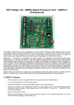
Refer to photo A) CN3-2 - Feedback potentiometer wipers. Use good quality 10K linear pots. The +ve direction of the pots should
match the +ve direction of rotation of the drive motors, otherwise the motor drive will be unstable.
Firmware B – “Pot 1” is SyRen controller high/low enable when JMP1 is closed (MA3 feedback)
B) 0V & 5V supply for the feedback pots or encoders – conveniently located beside the feedback signal connections.
DO NOT drive other electrical equipment from the 5V connection on the 40SPU-1 board.
C) CN3-1 – Feedback signals from US Digital MA3 absolute position encoders. Only the 12bit PWM MA3 encoder
types are supported – 10bit PWM and analogue types are NOT supported.
Firmware B – “MA3 1” is SyRen controller high/low enable when JMP1 is open (Pot feedback)
D) CN4-2 – I2C outputs to the Devantech MD03 motor speed controllers. The 0V and 5V connections can be used
for the logic supply to the MD03's. Note the I2C bus wire lengths must be kept to less than approximately 300mm.
The MD03 controllers must be set to the correct I2C addresses (Actuator 1 – 0xB0, Actuator 2 – 0xB2, Actuator 3
– 0xB4, see your MD03 documentation for the correct dip switch settings for this). Your normally closed actuator
end-of-travel limit switches and an Emergency Stop switch MUST be wired in series in the 5V line to the MD03's
to power-down the controllers if the actuators over-stroke or an emergency stop is required. To make your motion
platform drive failsafe it is essential that the logic supply voltage to the motor controllers is cut when over travel
conditions occur. Alternative emergency cut-of arrangements can be considered, however it is essential that if
loss of motion control is suffered for whatever reason then the drive to the motors is cut. This is best achieved by
limit switches that are physically triggered by the over travel.
E) CN4-1 – Upper connection pair is a normally closed pause switch loop. If this loop goes open the drive to the
motors is cut by the 40SPU-1 and the red and green LEDS flash together. A “Pause Output” switch can be wired
in this loop. If you don't use a Pause switch then you must wire a short loop between the connectors to disable
the trip detection.
CN4-1 – Lower connection pair provides alternative 0V and 5V power in
connections for the board – see F) below for important comments on the logic power supply.
F) DC-1 – Power-in connector to suit 2.1mm power plugs – tip +ve. The board supply must be a REGULATED 5V
2