1
DOEPFER
MIDI Analog Sequencer
MAQ16/3
User's Guide
Table of contents
Table of contents................................................................................................................... 1
Operating and Security Instructions ...................................................................................... 3
Preface.................................................................................................................................. 5
Connections .......................................................................................................................... 6
Power supply ..................................................................................................................... 6
MIDI-Connectors................................................................................................................ 6
CV/Gate-Connectors ......................................................................................................... 7
Operating Manual.................................................................................................................. 8
Controls at the front panel ................................................................................................. 8
Operation........................................................................................................................... 8
Switching the Sequencer On .......................................................................................... 8
Menu Structure............................................................................................................... 9
Menu 1: EVENT.......................................................................................................... 9
Menu 2: CHANNEL..................................................................................................... 9
Menu 3: FIRST/LAST STEP ....................................................................................... 9
Menu 4: PRESCALE................................................................................................... 9
Menu 5: MODE ..........................................................................................................10
Menu 6: SINGLE STEP .............................................................................................10
Menu 7: PRESET ......................................................................................................10
Menu 8: START/STOP ..............................................................................................10
Detailed Description of the Menus.................................................................................11
EVENT ......................................................................................................................12
CHANNEL .................................................................................................................17
FIRST/LAST STEP ....................................................................................................17
PRESCALE ...............................................................................................................17
MODE........................................................................................................................18
SINGLE STEP ...........................................................................................................19
PRESET ....................................................................................................................20
START/STOP ............................................................................................................22
APPENDIX A: Remote-Control of MAQ-Parameters via MIDI-Events ..................................24
Adjusting the MIDI channels XX and YY...........................................................................24
Program-Change Remote-Control ....................................................................................25
Noten-Event-Fernsteuerfunktionen ...................................................................................26
Control-Change Remote-Control ......................................................................................26
APPENDIX B: Display of MIDI-Errors...................................................................................27
APPENDIX C: MIDI Dump Request .....................................................................................28
APPENDIX D: Updating MAQs V1.0/V2.0 to V3.0................................................................29
APPENDIX E:Adjusting the CV outputs................................................................................31
Page 2
Operating and Security Instructions
Please follow the given instructions for use of the instrument because this will guarantee
correct instrument operation. Due to the fact that these instructions touch on Product
Liability, it is absolutely imperative that they be read carefully. Any claim for defect will be
rejected if one or more of the items was observed. Disregard of the instructions can
endanger the 6 month warranty.
The instrument may only be used for the purpose described in this operating manual. Due to
safety reasons, the instrument must never be used for other purposes not described in this
manual. If you are not sure about the intended purpose of the instrument please contact an
expert.
The instrument may only be operated with the voltage written on the power input on the rear
panel. Before opening the case disconnect the power plug.
All eventual modifications must only be carried out by a qualified person who will follow the
valid safety instructions. Every modification should becarried out only at the manufacturer or
an authorized service company. Any modification not released by the manufacturer leads to
the extinction of the operation permission.
With the introduction of a third person the warranty will be lost. In case of a destroyed
warranty seal, any warranty claim will be rejected.
The instrument must never be operated outdoors but in dry, closed rooms. Never use the
instrument in a humid or wet environment nor near inflammables.
No liquids or conducting materials must get into the instrument. If this should happen the
instrument must be disconnected from power immediately and be examined, cleaned and
eventually be repaired by a qualified person.
Never subject the instrument to temperatures above +50 øC or below -10 øC. Before
operation the instrument should have a temperature of at least 10 øC. Do not place the
instrument into direct sun light. Do not install the instrument near heat sources.
Keep the top side of the instrument free in order to guarantee proper ventilation, otherwise
the instrument could be overheated.
Never place heavy objects on the instrument.
All cables connected with the instrument must be checked periodically. If there is any
damage the cables must be repaired or replaced by an authorized person.
Transport the instrument carefully, never let it fall or overturn. Make sure that during
transport and in use the instrument has a proper stand and does not fall, slip or turn over
because persons could be injured.
Never use the instrument in the immediate proximity of interfering electronic devices (e.g.
monitors, power supplies, computers) since this could create disturbances within the
instrument and corrupt memory data.
The exchange of electronic parts (e.g. EPROMs for software update) is allowed only if the
instrument is disconnected from power supply.
The instrument should only be shipped in the original packaging. Any instruments shipped to
us for return, exchange, warranty repair, update or examination must be in their original
Page 3
packaging! Any other deliveries will be rejected. Therefore, you should keep the original
packaging and the technical documentation.
Attention:
In each electronic device there is some chance of data corruption (e.g. because of an EMC
disturbance). . In most cases a data corruption happens only once and it is not possible to
our find the reason. As mentioned above mostly nonrecurring EMC disturbances (e.g.
transients in the mains power supply) cause such data corruption and there is no way no
chance to protect oneself from them - except the data copy via SysEx.
This is why you should make a copy of all data now and then for the safety of your data.
Same is valid for the MAQ data too. For this purpose the MAQ has the dump feature that
enables to store your preset data via MIDI SysEx messages e.g. to a computer or MIDI
recording device. (APPENDIX A).
Also an backup could be very useful, if you delete or overwrite a preset by mistake.
When using the instrument in Germany, the appropriate VDE standards must be followed.
The following standards are of special importance: DIN VDE 0100 (Teil 300/11.85, Teil
410/11.83, Teil 481/10.87), DIN VDE 0532 (Teil 1/03.82), DIN VDE 0550 (Teil 1/12.69), DIN
VDE 0551 (05.72), DIN VDE 0551e (06.75), DIN VDE 0700 (Teil 1/02.81, Teil 207/10.82),
DIN VDE 0711 (Teil 500/10.89), DIN VDE 0860 (05.89), DIN VDE 0869 (01.85). VDE papers
can be obtained from the VDE-Verlag GmbH, Berlin.
Technical specifications are subject to change without notice.
Page 4
Preface
While studying this manual one may occasionally get the impression of slightly awkward
and/or complicated operating procedures. The reason for this is the fact that the MAQ was
initially designed about 3 years ago as a simple analog sequencer in the version 1.00.
However, due to user’s suggestions we found in the course of software development that
MIDI allows many more functional possibilities than would be the case with conventional
analog sequencers. In particular, we also incorporated a number of features which had been
requested by the well-known German band KRAFTWERK and which had not been planned
for originally. Consequently our original concept of a simple analog sequencer turned into a
rather sophisticated device which will hopefully satisfy even the most demanding users.
Unfortunately the increased sophistication of the MAQ had to be purchased at the expense
of user-friendliness. We nevertheless hope that the broad range of functions and features
will compensate our customers for this.
At this point we would also like to express our gratitude to the band KRAFTWERK
( www.kraftwerk.com ) for their cooperation and input during the development of the
MAQ16/3.
The software and hardware presently included with the MAQ16/3 is version 3.0x. It was
thoroughly tested by our firm as well as several beta-testers and found to be free of bugs.
Nevertheless, it has been our experience that the new version of a software package will
eventually reveal some hidden bugs after all. We would therefore appreciate it if our
customers would notify us in the event of their encountering a bug. We will then immediately
attempt to correct the problem as soon as possible and to release a software update to our
customers.
Please contact your local dealer if you need a software update.
If you want to order the update directly from Doepfer a processing fee of 20.- DM (or 20.SFr, 10.- Euro, 10.- US$, 150.- ÖS) has to be payed in advance (banknotes or stamps). As
soon as we receive the processing fee a new EPROM will be sent. Please tell us your
current software version and the serial no. of your unit. Otherwise the software update
cannot be performed.
Pay attention that the software update requires the exchange of the EPROM on the basic
board. For this the unit has to be opened, the present EPROM has to be removed and the
new one inserted. If your unit is still under warranty we recommend that the software update
should be performed only by authorized service personal ! If you damage the unit while
replacing the EPROM the warranty is lost !
Please note that the comment above is not valid for software upgrades which introduce new
features not initially included with version 3.X. For such upgrades not only a processing fee
is payable.
Page 5
Connections
All connectors are located at the rear panel.
Power supply
The MAQ16/3 does not have a built-in power supply. Instead it uses a plug-in type external
power supply (DC adapter). The connector is labeled „9V DC“ and is located next to the two
MIDI sockets. The primary reason for this feature is the fact that line voltages and plug types
vary considerably from country to country. Using a plug-in external supply the MAQ16/3 can
be used anywhere with a locally purchased power supply, thus keeping the retail price
down.The MAQ16/3 is switched ON by plugging the AC adapter into a wall outlet and
connecting it to the appropriate jack on the back of the case. There is no separate ON/OFF
switch.
MAQ16/3 sequencers sold in Germany do include an AC adapter for 230V mains supply.
In other countries the power supply is NOT included with the MAQ16/3 and must be
purchased locally by the user. The power supply must be able to deliver a voltage of 9-12
VDC (unstabilized), as well as a minimum current of 500mA. The polarity of the connector
must be the following: ring = GND, tip = +9V DC. If the polarity of the power supply is
incorrect, the MAQ16/3 will not function. However, there is no danger of damage to the
circuitry since it is protected by a diode.
MIDI-Connectors
Next to the power supply connector you will find the two MIDI connectors „MIDI-In“ and
„MIDI-Out“.
Connect the MIDI-OUT jack of the MAQ16/3 with MIDI-IN of the device to be controlled
(Expander, Synthesizer, etc.) via a suitable MIDI-cable.
The MIDI-IN jack of the MAQ is needed only if the device is to be synchronized via MIDI-IN,
if sequences of notes are to be transposed or if the MIDI remote control features are used.
Otherwise the MIDI-IN jack remains unused. It should be emphasized that the MIDI-IN jack
has no merge-function, i.e. incoming data is not passed on to the MIDI-output.
If the MIDI data controlling the MAQ are required for other MIDI equipment too a MIDI Thru
box has to be used.
If the MIDI data coming from the MAQ should be merged with other MIDI data a MIDI merge
boxed has to be used (e.g. the Doepfer MMR4/4 with 4 MIDI-Ins and 4 MIDI-Outs).
Page 6
CV/Gate-Connectors
In the middle of the rear panel you will find 6 miniature jack sockets (3.5 mm) labeled „CV1“,
„CV2“, „CV3“, „Gate 1“, „Gate 2“ und „Gate 3“. For each of the 3 potentiometer rows one CV
output and one Gate output are available. The CV/Gate outputs are compatible with the
DOEPFER A-100 modular system and many other analog synthesizers.
The CV voltage range is 5V with an offset voltage of about 0.25V (i.e. effectiv
+0.25...+5.25V). The offset voltage may be compensated with the tune knob and/or or the
keyboard of the synthesizer or module to be controlled as all control voltages are additive in
standard 1V/octave analog systems.
If „note“ is assigned to the corresponding row the CV output follows the 1V/octave
characteristics used by most of the vintage synthesizers (1 semitone = 1/12V = 0.083V). In
all other cases (e.g. controller) the voltage range is about 0.25V (knob full ccw) .... 5.25V
(knob full cw).
For each CV output there is a trimming potentiometer inside the unit to adjust the CV scale if
necessary. The scale is trimmed in the factory to 1.00V/octave. If you want to change or
correct the setting of the scale see appendix E „Adjusting the CV-Outputs“.
The factory setting of the Gate outputs are is voltage trigger 0/+8V. If desired the outputs
can be modified for S-trigger (switched trigger, used e.g. by Moog synthesizers) in the
factory or by an authorised service company.
Every modification must only be made by authorized service. Otherwise the warranty will
become invalid.
Note: Not correctly adjusted CV scale is no reason for warranty. If the only „defect“ in a MAQ
unit sent for repair is the incorrect scale this is no matter of warranty.
Page 7
Operating Manual
Controls at the front panel
The MAQ16/3 features the following controls and displays:
•
•
•
•
•
3 rows of 16 potentiometers (dials) and LEDs each
3-digit LED-display
8 MENU-buttons in 2 rows of 4 buttons each
8 LEDs (serving as indicators for the MENU-buttons)
1 Data-entry dial
The three rows of dials serve to adjust the sequences. The LEDs above the dials indicate
the active step in each row.
The 8 MENU-buttons and their indicator LEDs are used to activate the various operating
modes. The data-entry dial allows rapid editing of the desired parameters.
Operation
Switching the Sequencer On
After the power supply is plugged-in the display should show the software version (e.g. 350
for version 3.50) and the 8 LEDs light for a short moment.
After that the display shows the tempo in BPM (Beats per minute), which can be altered via
the data entry dial. The 8 LEDs above the MENU-buttons will be off (i.e. no menu is
selected).
If this is not the case either the MAQ16/3 or the power supply is defective. Please first check
the power supply before you return the MAQ. Maybe the polarity of the power supply used is
wrong (ring must be GND, pin must be +9...12V, a minimum current of 500mA is required).
After turning the MAQ on preset 1 is called up and you are in the Edit Mode. The positions of
the 48 knobs do not correspond to the Midi/CV data sent via MIDI out/CV out if you start the
sequencer with the Start/Stop button as the 48 step values are taken from preset 1 (for
details see Preset).
H If you have updated from 2.0 to 3.0:
The automatic storage of all parameters into preset 1 is no longer available. If you want to
store the last configuration you have to store it explicitely into one of the presets before
turning the MAQ off. Use preset 1 if the configuration should be available after turning the
MAQ.
Page 8
Menu Structure
There are 8 different menus which can be selected via the 8 MENU-buttons by pressing the
appropriate one. The LEDs above the buttons will indicate which one is active at any given
time. One can exit a menu at any time simply by pressing another MENU-button. If no menu
is selected all LEDs are off and the display shows the tempo in BPM.
The following menus are assigned to the 8 MENU-buttons:
Upper row:
1: EVENT
2: CHANNEL
3: FIRST/LAST STEP
4: PRESCALE
Lower row:
5: MODE
6: SINGLE STEP
7: PRESET
8: START/STOP
Menus 1-6 always refer to one of the three rows of dials. Menus 7-8 are global, i.e. they refer
to the whole sequencer rather than a specific row.
In the next few paragraphs we shall briefly explain the functions of the 8 menus, prior to
discussing them in detail.
Menu 1: EVENT
In this menu a certain type of MIDI-instruction (Event) is assigned to each row. The most
important event types are Note ON/OFF, Velocity, Controller, Pitch-bend and Aftertouch. In
addition a row can be assigned time function (i.e. duration of the step), dynamic switching of
the MIDI-channel or additional transposition of another row.
Menu 2: CHANNEL
This menu is used to assign a row to a MIDI-channel. The row will transmit the MIDIinstructions entered in MENU 1 on the channel selected in this menu, unless dynamic MIDIchannel switching has been activated.
Menu 3: FIRST/LAST STEP
The length of each of the three rows of dials can be limited. In this menu the user
determines the first step in which the sequence begins, as well as the last step after which
the unit jumps back to the first column. Since first and last step can be adjusted separately
for each row, it is possible to generate rather complex sequences.
Page 9
Menu 4: PRESCALE
For each row the time difference (in units of MIDI-Clock events) between events (MIDIinstructions) can be predetermined. The time difference is a tempo-divisor (always a whole
number) which refers to the MIDI-Clock or the internally generated tempo, respectively.
In case of NOTE-events one can also adjust the time between NOTE ON and NOTE OFF
(i.e. Note duration).
Among other things one can use this menu to cause different rows to run at different speeds,
although always synchronous with the MIDI-Clock.
Menu 5: MODE
For each row one of eight modes can be chosen: Forward, Reverse, Pendulum 1, Pendulum
2, One-Shot 1, One-Shot 2, One-Note or Random.
Menu 6: SINGLE STEP
This menu is used to select single step-mode. It is used primarily to adjust each individual
step, for example in cases where the desired sequence is not to be determined
experimentally but a prepared sequence is to be entered.
The function can also be used for interesting effects during live performances ("Scanning" of
a sequence or single step-improvisation, for example) since single-step mode also runs
synchronous with the MIDI-Clock.
This menu allows to mute/demute single steps as well.
Menu 7: PRESET
In this menu the presets are managed. 30 presets can be stored for subsequent retrieval.
The manual DUMP-function via System-Exclusive-instructions can be initiated in this menu.
Menu 8: START/STOP
This is not a menu as such, but rather a START/STOP/CONTINUE button.
By pressing the button one alternately starts and stops the sequence. The tempo in beats
per minute (BPM) appears on the display in this mode and can be adjusted via the dataentry dial.
If the data-entry dial is turned above the maximum tempo value of 254 (Display shows „ETC“
or „ETS“) the synchronization of the MAQ takes place externally via MIDI-IN (i.e. external
trigger).
Page 10
Detailed Description of the Menus
The following general remarks apply to all menus and will not be repeated in the description
of each individual menu:
1. A menu is selected by pressing the corresponding MENU-button. The menu selected is
visually indicated by an illuminated LED. Exception: In the Preset menu the LEDs 7 and 8
are illuminated.
2. One can exit from a menu by pressing a different MENU-button except the Start/Stop
button.
3. In menus 1-6 one can select the desired row by pressing the same MENU-button again,
since these menus refer to one of the three rows of dials. The corresponding row is indicated
by a glimmering display of all LEDs of the row. Only the step selected lights up with full
brightness.
The process is circular 1-2-3-1-2..., i.e. if the button is pressed again while row 3 is selected
the program jumps back to row 1.
4. The parameters within the menu selected are adjusted via the data-entry dial beneath the
control-panel.
H If you have updated from 2.0 to 3.0:
The display of the row selected by one of the three decimal points in combination with the
toggling of the display has been cancelled to the credit of the more comfortable glimming
display. The data potentiometer of V1.0/2.0 has been replaced by an endless rotary encoder
(alpha dial).
Realtime Operation
All parameters in menus 1-6 can be altered during operation, i.e. while the sequence is
running. However, please note that this may lead to undesired side-effects. So we suggest
to change settings in the menus 1-6 only while the sequencer has stopped until you are
familiar with the controls.
In particular a change in the type of MIDI-Event (menu 1) or the MIDI channel (menu 2) while
the sequence is running may trigger unexpected effects.
For example, if the operating is changed from Note to Controller during operation, notes can
get stuck since a NOTE ON-instruction may suddenly be missing its corresponding NOTE
OFF-instruction., Another example are undesired controller messages while turning the
data-entry dial in MIDI-event mode (Menu 1) while a sequence is running (e.g. Volume/Ctr.
# 7 with data = 0 may mute a midi channel / Modulation/Ctr. # 1 with data = 127 may cause
high modulation).
It is therefore not recommended to make such substantial changes during operation,
especially since they would not make a great deal of sense during live performances
anyway.
On the other hand, FIRST/LAST STEP (Menu 3), TIME (Menu 4) or MODE (Menu 5) lend
themselves very well to modification during operation, including live performances.
Page 11
EVENT
In this menu the selected row of dials is assigned the desired MIDI-Event. The assigned
MIDI-Event is shown on the display in abbreviated form.
The following MIDI-Events are available:
Display
Type of event
Remark
---
no function
number between
0 - 127
nA1 ...
nA5
free definable Controller (like (9) )
row
switched off
(9-1)
Note on/off absolute
1...5 octaves
(1)
nr1 ...
nr5
Note on/off relative
1...5 octaves
(1)
d.Y.n.
Dynamics/Velocity
(2)
C0,C1,C2...
Controller
(9)
PIt
PIP
PI-
Pitch Bend
Pitch Bend positive only
Pitch Bend negative only
(3)
(3)
(3)
At
After Touch (monophonic)
Prg
Program Change
(4)
Cn1
MIDI channel for row 1
(5)
Ad1
addition to row 1
(6)
A.P 1
Poly-AT/Polypressure
for row 1
Poly-AT/Polypressure
for row 2
A P .2
(7)+(1)
(7)+(1)
t.4. .
t.8. .
t.1.6.
t.3.2.
Step-duration 1-4
Step-duration 1-8
Step-duration 1-16
Step-duration 1-32
(8)
(8)
(8)
(8)
PA1 ...
PA5
note on/off absolute
1...5 octaves mit pause
(1)
Pr1 ...
Pr5
note on/off relative
1...5 octaves mit pause
(1)
Remarks to the individual types of event:
Page 12
(1): Note instructions
If Note ON/OFF is assigned to a row one can choose between the following options:
1. Symbol: Normal (n) or with pause (P)
2. Symbol: Absolute (A) or relative (r) operating mode
3. Symbol: Octave-range (between 1 and 5)
If "Normal" is selected, then the entire dialing range of each of the 48 dials generates Noteevents. If "Pause" is selected, turning a dial all the way to the right will generate a pause
rather than a Note-event (MUTE-function). The LED of a step muted will not light up while
the sequence is running.
If "Absolute" is selected, then the note is entered directly with the dial and will not be altered
by incoming note-instructions. In this case the note-values start at MIDI-Code 36 (= the low
C on a 5-octave keyboard). In "relative" NOTE ON-instructions entering via MIDI-IN are used
for transposition of the sequence, i.e. the note-values entered with the dials are added to
those coming from MIDI-IN. In order to be able to implement the TRANSPOSE-function, the
MIDI-channel of the incoming note-instructions must be the same as that of the row.
There are 5 different scales ranging from 1 to 5 octaves for both all operating modes. For
example, with nA1 the range of notes for a full turn of a dial is 1 octave, with nA5 it is 5
octaves. For the corresponding CV output this means a voltage difference of 1V (nA1) ... 5V
(nA5). The reference note for lowest CV (about 0.25V) is the note with MIDI code 36 (C).
If a row of notes is combined with a velocity-row (see remark 2), then the velocity values are
supplied by this second row. If no other row is defined as velocity-row, then the noteinstructions are sent with a velocity-value of 100.
If a "note"-row is combined with a poly-pressure row (see remark 7), then the note-row no
longer sends Note ON/OFF-instructions, but polyphonic aftertouch-events instead. The notevalue of the Poly-AT-instruction is generated by the note-row, the poly-pressure-value is
generated with the poly-pressure-row (A.P 1 or A P.2). This approach to combining a noterow with a poly-pressure-row was chosen because "Note"- and "Poly-AT"-instructions are
very similar (i.e. 3 bytes in length). In both cases the status-byte is followed by the note-byte
and then the velocity-byte (for Note ON/OFF) or the pressure-byte (for Poly-AT),
respectively.
(2): Velocity/Poly-Pressure
Under MIDI the velocity-instruction is coupled to the note-instruction. Thus, if velocity has
been assigned to one row, it must be combined with a row which generates noteinstructions.
The three decimal points of the display are used to indicate which row(s) have been
assigned to the velocity-row. For example, if NOTES ON/OFF has been assigned to row 1
and if the velocity-values are to be provided by row 2, then the Event-type "d.y n" is to be
entered for row 2, i.e. only the left decimal point may be illuminated as an indication that row
2 and its velocity-instructions have been combined only with row 1. In principle, one can
combine the velocity-row with more than one row providing notes. For example, "d.y n."
would indicate that row 2 (velocity-row) has been combined with both, row 1 and row 3.
However, the user must make certain that the other two rows provide note-instructions.
Furthermore, one should remember that one velocity-row now simultaneously controls two
note-rows. It is left to the user to decide on the usefulness of such an arrangement.
Page 13
If a dial is turned all the way to the left (i.e. Velocity = 0) no note-instruction is generated,
instead a pause of the corresponding length will result.
(3): Pitch-Bend
Three seperate ranges were set aside for pitch bend: Full range (0...127), positive values
only (64...127) and negative values only (0...64). If the full pitch-range is selected there will
be a plateau around the center position of the dial in order to make it a little easier to find the
neutral pitch-position.
(4): Program-Change
With this instruction it is possible to dynamically switch sounds during a sequence, provided
the expander being used permits this feature. Many expanders have a certain delay time
before a new note-instruction actually starts generating a sound after a program-changeinstruction. With such expanders the program-change event cannot be properly utilized.
(5): Dynamic MIDI-Channel-Switching
With Cn1 the dynamic MIDI-channel-switching (1...16) for row 1 can be assigned to rows 2
or 3. The sequence running in row 1 will then be dynamically distributed onto the MIDIchannels which have been selected with the dials in row 2 or 3. The MIDI-channel settings
for row 1 (see Menu 2) are then suspended. In order for this function to work properly, an
appropriatenumber of receivers (Expanders) must be available on several MIDI-channels.
MIDI-Multimode-Expanders which can receive on several different channels simultaneously
lend themselves particularly well to this application.
(6): Addition/Transposition
Ad1 permits values entered with the dials in rows 2 and 3 to be added to row 1. For example,
if row 1 provides note-instructions, then this feature would provide an additional transposition
capability. It would permit the alteration of the sequence of row 1, without modifying the
sequence itself. Since rows 2 and 3 and row 1 can run at different speeds it is for example
possible to let the transposition (Rows 2/3) take effect only after each half or fully completed
run of row 1.
(7): Polyphonic Aftertouch
In order to send polyphonic aftertouch (Poly-AT)-instructions, one of the four types of noteevents (nA, nr, PA, Pr) is assigned to row 1 or 2. A second row is then assigned "A.P 1"
(Poly-AT for row 1) or "A P.2" (Poly-AT for row 2). The note-row is then responsible for the
pitch, the AP-row for the poly-pressure values.
The PolyAT-event is very similar to the normal Note-event with velocity. In both cases the
first row is used to set the note-values. The difference lies in the fact that with Note-events
the second row is used to determine velocity, whereas with PolyAT-events the second row is
used to determine pressure-values.
Page 14
(8): Step-duration (time)
The step-duration is not directly linked with a MIDI-event. It merely provides the duration for
the step in question. If step-duration is assigned to a row it can refer to one row, two rows or
all three rows. The indication is provided by the three decimal points of the display.
If, for example, "t.4. ." is entered for the bottom row (Row 3) it means that the settings
entered on the dials of row 3 are valid for all three rows. "t 4. ." would indicate validity only for
the two bottom rows. In order for the user to be able to control the step-duration on the
bottom row, it must also refer to that row (i.e. the third decimal point on the display must be
illuminated in our example). Otherwise the time-row will run in constant steps and will pass
the step-duration values only to the other row(s) activated.
There are four possible scaling factors for the dials: Base time x 4, x 8, x 16, x 32. The base
time results from the (internal or external) MIDI-clock. The step-duration can only be
increased in whole multiples of the base time. The digits 4, 8, 16 and 32 refer to the
maximum scaling factor (with respect to the clock) which can be reached if a control dial is
turned all the way up.
If only small time differences between steps are desired "t4" should be selected, for larger
differences one should select "t 8", "t16" or "t32". If a dial in the step-duration-row is turned
all the way to the left, then the step in question will be omitted, i.e. this serves as SKIPfunction.
The timing of each row is also influenced by an adjustable prescale factor (Menu 4:
PRESCALE/TIME). If the step-duration function is assigned to a row the prescale factors
entered in Menu 4 are in effect as well. Very complex timing arrangements can thus be
programmed, although these will always within the framework of the MIDI-clock.
In principle the step-duration can be controlled with any one of the three rows of dials.
However, for technical reasons we recommend that only the bottom row is used for this
purpose, since the software has been optimized for this.
(9): Controller
32 different MIDI controllers are available. The currently selected controller no. is shown in
the display (e.g. C0, C9, C64, C70). A selection of 32 out of the 128 possible MIDI
controllers is available (0-19, 64-74, 84).
(9-1): free definable Controller
(New since version 3.5)
At the time the MAQ firmware was basically programmed the possibility to choose one of a
selection of 32 fixed controller numbers seems to be sufficient. (9)
By now ( after almost 10 years) however most of the 128 possible controller numbers are
assigned with useful functions, so that now often the request came up, that you could create
all of the 128 controllers with the MAQ.
To keep the compatibility to the previous software versions the fixed controller values (9) are
left as they are, though they are now strictly speaking unnecessary.
The new free definable Controller you will find now at the beginning of the EVENT's direct
after '---' and before 'nA1' at the up to now not occupied position 2.
Page 15
Because of space problems in the display only the controller number could be shown ( so no
'C' as used for the fixed conbtrollers (9) )
To select the number free between 0 - 127 you now have to press additional the 'Presets'button, which is indicated by lighting the LED of this switch.
Now you can change the controller number with the data entry dial. So the dial is used in
this situation not to select the type of the event, but also the number of the free controller
event. To fall back to the 'old' edit mode, where you can select the event type, you have to
press a different menu button except 'EVENT'. And then select once more the Event menu.
Though it's possible to switch between the rows in the new edit mode by pressing the
EVENT-button, you could only view the assigned event types, but not change them, because
the entry dial is locked for all 'normal' edit operation.
Remark:
For an update of an older MAQ version ( 3.4 and under) to a version 3.5 or higher.
Relating to receive an 'old' sysex dump (Appendix C) there's now change, because also in
the older version the complete memory was dumped. So also the memory which is now used
by the free controller numbers, which was only undefined up to now.
Therefore you now have of course to define these values, if you want to use them in a
preset.
Relating to a dump of a single preset the 3 new bytes are simply put at the end of the string.
So to receive an 'old' dump will work without problems, but will cause the display of an midierror. (Which is o.k. because realting to the new format, there are really 3 missing bytes.)
But you must not pay attention to this, but also simply define the free controllers, if you now
use them.
We would like to emphasize one more time at this point that not every arrangement possible
is also sensible. One could of course assign step-duration or velocity to all three rows, but
this would certainly make no sense ! Nonetheless, we deliberately decided not to outright
exclude certain configurations, in order to avoid limiting the potential of the MAQ from the
start. Since this allows for the possibility of nonsensical configurations, we urge all users to
make sure that the configurations programmed do make sense. Otherwise there is a
potential for uncontrolled reactions and side effects.
For example, if a velocity-row is combined with an monophonic aftertouch-row, then the
velocity-value entered via the dials will overwrite the aftertouch-values!
If on occasion the MAQ behaves in unexpected or undesired fashion, the user should
review the configuration entered to make sure it actually makes sense.
Page 16
CHANNEL
In this menu a MIDI-channel is assigned to the designated row of dials. The channel is
selected via the data-entry dial. If a row has been assigned Velocity, Step-duration, Addition
(Ad1) or Dynamic MIDI-channel (Cn1) in menu 1, then the MIDI-channel selection of menu 2
is without meaning since in those cases the MIDI-channel is determined by the
corresponding row(s).
FIRST/LAST STEP
In this menu the first ("F . . ") and last ("L . . ") active step in each row are selected.
Repeated pressing of the MENU-button will allow the first steps ("F . .") of the three rows to
be entered first, followed by the last steps ("L . .") of the three rows. After the selected last
step of a row has been reached the program jumps back to the selected first step of the row
(in forward mode, see menu 5). Since these settings are made separately for each row it is
possible to generate very complex sequences which will repeat only after several runs.
Another way to create interesting effects is to combine a note-row with a velocity-row of
different length. This will result in the combination of notes and velocity-values constantly
being shifted, thus creating a lively accentuation. The same holds true for a step-duration
assigned to row 3. If this row is made shorter or longer than the note-row with which it is
combined, the step-durations will constantly vary with the notes. One may also change the
values while the sequence is running, i.e. lengthening or shortening the sequences during
operation. This will substantially enhance live performances and can also be used for
improvisations or experimental pieces.
PRESCALE
In this menu the period between two events (in MIDI-clock units) can be adjusted for each
row. For note-events the note-duration can be adjusted in addition. The abbreviations "g"
and "n" are being used. "g" stands for gate-time, this is the time between two events of the
same type. An example would be the time between two Note ON-instructions. "n" stands for
note-duration, i.e. the time between a Note ON-instruction and its associated Note OFFinstruction.
The setting of note-duration is relevant only if the row in question has been assigned to noteevents (nA, nr, PA, Pr). There is no "switching off" in the fashion of NOTE OFF-instructions
with any of the other types of instructions, such as controllers, pitchbend and aftertouch.
Repeated pressing of the menu-button will initially take the user into the gate-time section of
the menu, where the gate-times are entered (g . .) for the three row. This section of the
menu is followed by that for adjustment of note-lengths (n . .). It should be remembered that
note-length must always be less than gate-duration. If note-length is set to "1", it will always
automatically be equal to gate-duration and need not be changed separately if gate-duration
is changed.
The two-digit numbers displayed behind "g" or "n" refer to the MIDI-clock. For example, a
setting of "g06" means that after 6 MIDI-clocks the row in question jumps to the next step. If
two rows are to run at equal speed, one must enter the same values for gate-duration in
each row.
If one row is to run half as fast as the other, one must enter a value for gate-duration which
is twice that of the other row (i.e. 12 for our example). Uneven ratios are also possible.
Page 17
In MIDI the duration of a quarter note is defined as 24 clocks. If you combine the MAQ with
another MIDI-clock controlled unit (drum machine, computer sequencer etc.) you have to
ensure that the MAQ is running at the same musical tempo as the other unit(s). In this case
we recommend you choose a value of 24, 12 or 6 for the gate time, i.e. to select a musical
period of a quarter, a eight or a sixteenth note between two sequence steps.
The separate adjustment of the prescale-factors for each row make extremely complex
timing arrangements possible, although these will always be referenced to the shared MIDIclock. If step-duration is assigned to row 3, the step-duration and the effects of the prescalefactor from menu 4 will overlap. In combination with different "First/Last steps" in the three
rows one obtains very complex sequences which no longer appear to have any timing-based
relationship, but which always run synchronously via the MIDI-clock.
MODE
There are 13 possible operating modes for each row: forward, reverse, 2 pendulum types,
random, 2 one-shot types and single note. Additionally for the first 5 types can be selected
between Clock- and Note-Trigger, i.e. whether the advance to the next step is caused by
MIDI clock or note events.
Display
FOr
bAC
PE1
rnd
PE2
OnS
Onr
OnE
Operating Mode
vorwärts Clock-gesteuert
rückwärts Clock-gesteuert
Pendelmodus 1 Clock-gesteuert
zufällig Clock-gesteuert
Pendelmodus 2 Clock-gesteuert
Einfach-Durchlauf 1 Clock-gest.
Einfach-Durchlauf 2 Clock-gest.
Einzelnote Clock-gesteuert
nFr
nbC
nP1
nrd
nP2
vorwärts Noten-gesteuert
rückwärts Noten-gesteuert
Pendelmodus 1 Noten-gesteuert
zufällig Noten-gesteuert
Pendelmodus 2 Noten-gesteuert
(forward)
(backward)
(random)
(One Shot)
The difference between Clock controlled and Note controlled modes is the trigger for the
advance to the next step. The Clock controlled modes are triggered by the (internal or
external) MIDI Clock. This is the standard mode for sequencers. The Note controlled modes
are triggered by an incoming Note event at the MIDI In. The MIDI channel of the incoming
Note event must fit with the MIDI channel assigned to the corresponding row.
In Pendulum 1 the first and last step are played twice so that the row has the same timing as
another row with the same length in forward/backward. In Pendulum 2 the first and last step
are played only once. In this case the effective length of the row is only 15!
In One Shot mode 1 (OnS = One Shot Single) the running stops when last step is reached.
Restart is possible only by using the Start/Stop button. In One Shot mode 2 (Onr = One Shot
Retrigger) the next row in One Shot mode is started when the last step is reached.
With this feature you may create a 48 step sequencer if all 3 rows the mode „Onr“ is
assigned. Of course the MIDI event types, channels, tempo and so on should be the same.
But it may be possible that each row of the 48 step sequence is running with different tempo
or generating different MIDI event types on different channels.
Page 18
In the One Event mode only one step is played (the same effect as first step=last step). This
mode makes sense only in combination with the remote control features of the MAQ. You
may scan through a sequence with remote functions (for details see Appendix A „Remote
Functions via MIDI In“).
SINGLE STEP
This menu selects the single step-mode. It may be used for programming a given sequence
step by step or for experimental purposes. Additionally single steps can be muted/demuted.
When entering the menu first time you are in the Global Single Step Mode. This means that
you have access to all three rows at a time. The data-entry dial is used to select one of the
steps 1-16. The step in question will be selected in all three rows and is indicated by three
illuminated LEDs one for each row. Each step is scanned in the previously selected tempo.
For example, if NOTE ON/OFF has been assigned to all three rows in menu 1 one can now
easily set the desired triad for each column. If only one or two rows are to be adjusted, then
the undesired row(s) can be temporarily disabled in menu 1 (Event-type "---") or by using the
mute feature (see below) for a single step.
H If you have updated from 2.0 to 3.0:
The Global Single Step Mode is equivalent to the Single Step Mode of V2.0 with one
exception: the display shows the step/column number rather than the data value of a step. In
V3.0 the data value of a single setp is displayed only in the Single Step Mode for a Single
Row (see below).
If you press the menu button once again you enter the
Single-Step-Mode for a single Row
In this mode one of the 3 rows is glimmering. With the data knob one step within the
glimmering row can be selected. Using the menu button the next row is selected. The data
value of the step selected - i.e. the MIDI value transmitted - appears in the display. This
value corresponds not necessarily to the knob position. If a preset was called up and the
knob position was not yet changed the display shows the value from the preset memory (for
details see chapter 2.2.3.7. Preset). Consequently the single step mode can be used to
display the values of a preset sequence. Only if preset 0 was called up or if the knob was
turned the knob positions correspond to the data values displayed !
The data range is different for different event types (e.g. nA1 = 36...48, nA2 = 36...60,
nA3=36...72, nA4=36...84, nA5=36...96, Controller = 0...127 and so on).
Mute-Programming
The Start/Stop button is used to mute/demute the step selected. The function is toggling i.e.
repeatet pressing the Start/Stop button performs mute-demutes-mute..... and so on. In case
a step is muted the corresponding LED remains dark.
Attention: The Start/Stop button has a special function in this mode and cannot be used to
leave the menu or to start/stop the sequence!
Using the menu button to select a row and the data knob to select a step within the row each
single step of the MAQ can be adressed and muted/demuted with the Start/Stop button.
Page 19
The mutes remain effective after leaving the Single Step Menu. Thus you have a tool to
program the mutes within the MAQ without using the remote control functions via MIDI In
(see Appendix A).
To reenter the Global Single Step Mode when beeing in the Single Step Mode for one Row
first you have to leave the menu by pressing another menu button (except the Start/Stop
button) and enter the Single Step menu again.
The single step-mode can also be used for live performances and experimenting. For
example, once a sequence or chord-combination has been completed, then each of the 16
steps can be selected in realtime via the data-entry dial (i.e. each step can be dynamically
"scanned"). Output continues to occur in step with the internal or external MIDI-clock. It is
also possible to achieve spontaneous changes by turning the dials of the currently selected
step.
Use of the single step-mode should definitely not be limited to the input of a sequence, but
should also be used for experimentation during live performances.
PRESET
This global menu is used to manage the 30 available presets and to manually trigger the
DUMP-function. Up to 30 complete sequences can be stored and retrieved (i.e. all
parameters and the settings of the 48 dials). Preset 1 has a special status here. When the
MAQ is switched ON all parameters including the data values of the 48 potentiometers are
retrieved from Preset 1. Thus when turning on the MAQ the 48 knob positions do not
necessarily correspond to the MIDI data sent when starting the sequence.
H If you have updated from 2.0 to 3.0:
Starting with V3.0 the 48 data values of each preset can be edited as well. The automatic
storage of all parameters into preset 1 is no longer available. If you want to store the last
configuration you have to store it explicitely into one of the presets before turning the MAQ
off. Use preset 1 if the configuration should be available after turning the MAQ.
When the MENU-button is pressed the LEDs 7 (Preset) and 8 (Start/Stop) will go on to
indicate the exceptional position of the global Preset menu with 2 LEDs.
Page 20
Calling up a Preset
A preset number from 0-30 can be selected via the data-entry dial. To call up the preset the
Start/Stop button has to be pressed. The Start/Stop button has the „Enter“ function in the
Preset menu.
Preset 0 has a special status. It corresponds to the actual current setting of the 48 dials on
the front panel. Preset 0 can be chosen to start the programming of a new sequence as in
this special case the 48 knob positions really reflect the MIDI /CV data sent via MIDI Out
and/or CV/Gate. The other parameters of preset 0 are predefined as follows: event type nA1
for all rows, MIDI channel 1/2/3, first step = 1, last step = 16, gate/note divider = 6, mode =
forward.
Preset 0 can also be used as an „emergency brake“ if the parameters of the sequence are
completely disarranged and a new start seems to be easier than readjusting each single
parameter.
Presets 1 - 30 refers to any previously stored presets.
If one exits the menu in this mode by pressing another button except Preset and Start/Stop
the preset displayed is not called up.
Edititing a Preset
After calling up a preset as described above it can be edited. To edit one of the 48
potentiometer values you only have to turn the knob in question. The software recognizes if
a knob was turned and takes in this case the value from the front panel knob and no longer
from the preset memory. If you turn one by one all the 48 knobs the complete frontpanel
setting corresponds to the data sent via MIDI/CV.
The other sequence parameters (event, channel ....) may be adjusted as described in the
chapters 2.2.3.1. - 2.2.3.6. The modified sequence may be stored in one of the preset
memories as discribed in the following paragraph.
Storing a Preset
If the Preset button is pressed a second time, all 8 LEDs will go on as a visual warning of the
impending storing procedure. If a preset-number (1-30) is now entered via the data-entry dial
and the Start/Stop button („Enter“) is pressed, then the current settings of the 48 dials and
the current parameter-values are stored in the selected preset. Any sequence previously
stored in this location will be overwritten and is thus irretrievably lost!
Manual Dump
If preset "0" is selected for storage, then the manual DUMP via MIDI-OUT of the actual
preset is triggered. In this case the data is not stored, instead the entire content of the
actual preset is dumped via MIDI in form of System Exclusive-instructions. The dump of the
complete memory is described in Appendix C.
Initialisation the Preset memory
Page 21
In order to initialize one preset or the whole preset-memory it is necessary to press and hold
the Preset button for a few seconds while the MAQ is switched ON (i.e. when plugging in the
power supply cable). In this case the MAQ starts the initialising routine rather then the
normal software. The LEDs 1-6 are illuminated to indicate this special mode. The display
shows „000“ and can be adjusted with the data dial between „000“ and „030“. The
initialisation is triggered by the preset button and depends upon the display before pressing
the preset button:
➩ the whole preset memory is initialized
(30 presets)
1...30 ➩ only the preset displayed is initialized
0
In case „0“ the LEDs flicker like a binary counter to indicate the initialisation. This function
will irretrievably erase the preset(s) and should thus be used with caution! After initialisation
the MAQ must be turned off and on again to enter the regular mode.
Presets initialized imply the parameters from preset 0 (i.e. event type nA1 for all rows, MIDI
channel 1/2/3, first step = 1, last step = 16, gate/note divider = 6, mode = forward). The data
values are taken from actual front panel setting of the 48 potentiometers. So you have to
turn all knobs full ccw if you want to initialize all data with 36 (minimum value of event nA1).
START/STOP
This is not a menu but a Start/Stop-button. Pressing this MENU-button will alternately start
or stop the sequence. The appropriate MIDI-instructions START, STOP or CONTINUE are
sent along with MIDI-clock via MIDI-OUT.
In case of START the sequence starts from the last configuration (no resetting of the three
rows to step 1, MIDI-OUT: CONTINUE / $FB). If all three rows are to start with step 1
(Reset) then the START/STOP-menu must be briefly exited and reentered (MIDI-OUT:
START / $FA).
In this menu the display will show the tempo in beats per minute (BPM), the tempo can be
adjusted with the data-entry dial.
Page 22
External Synchronisation
In order to synchronize the MAQ16/3 with an external MIDI-clock via MIDI-IN, one must turn
the data-entry dial all the way over the maximum (254) or minimum value (50). The display
will then show „EtS“ or „EtC“ .
In case of „EtS“ (external trigger start mode) only an incoming MIDI Start event resets the 3
rows to first step. An incoming MIDI Continue the sequence continues from the last position.
In case of „EtC“ (external trigger continue mode) incoming MIDI Start or Continue resets the
3 rows as well.
When „EtS“ or „EtC“ is selected no longer the internal Clock generator is used but only
incoming MIDI Clock data as timing basis.
Page 23
APPENDIX A: Remote-Control of MAQ-Parameters via MIDI-Events
PLEASE NOTE: This type of remote control "alienates" the MIDI-specification from its
original purpose and does therefore not conform to MIDI. If channels XX and YY are to be
used for other purposes without addressing the MAQ, then corresponding MAQ function
must be turned off (MIDI channel 0).
The remote control feature was deliberately not implemented via SysEx since the required
MIDI-Events
are
difficult
or
impossible
to
generate
with
a
normal
synthesizer/masterkeyboard, whereas it was our intention to allow the user to play the MAQ
via a keyboard/synthesizer, much like any ordinary expander. However, the MAQ does not
interpret PRG-Change and Note-events on the channels XX and YY as an expander would.
Instead, the MAQ's main parameters which can be viewed as events which make musical
sense are controlled via PRG/Note.
Adjusting the MIDI channels XX and YY
In order to adust the MIDI channels XX and YY it is necessary to press and hold the Channel
button while the MAQ is switched ON (i.e. when plugging in the power supply cable). In this
case the MAQ starts the routine for adjusting the MIDI channels XX/YY rather then the
normal software. The MIDI channel of row 1 (upper row) corresponds to MIDI channel XX
(channel for preset calling up via MIDI Program Change), the channel of row 2 (middle row)
corresponds to MIDI channel YY (remote channel).
The channel is adjusted as in the normal software mode. In this special mode even MIDI
channel „0“ can be chosen and means that the corresponding function is turned off.
After adjusting the channels XX/YY the MAQ must be turned off and on again to enter the
regular mode.
Page 24
Program-Change Remote-Control
Function
select row 1
select row 2
select row 3
Midi-instruction
PRG-Change 1
PRG-Change 2
PRG-Change 3
Hex-Code ( Midichannel 16 = F)
CF 00
CF 01
CF 02
entire row active
entire row off
All steps of a row
active individually
All steps of a row
off individually
PRG-Change 4
PRG-Change 5
PRG-Change 6
CF 03
CF 04
CF 05
PRG-Change 7
CF 06
Betriebsarten:
Forward (FOr)
Backward (bAC)
Pendulum 1 (PE1)
Random (rnd)
PRG-Change 9
PRG-Change 10
PRG-Change 11
PRG-Change 12
CF 08
CF 09
CF 0A
CF 0B
Step 1 on
Step 2 on
...
Step 16 off
PRG-Change 17
PRG-Change 18
.....
PRG-Change 32
CF 10
CF 11
.....
CF 1F
Step 1 off
Step 2 off
...
Step 16 aus
PRG-Change 33
PRG-Change 34
.......
PRG-Change 48
CF 20
CF 21
......
CF 2F
First Step = 1
First Step = 2
...
First Step = 16
PRG-Change 49
PRG-Change 50
......
PRG-Change 64
CF 30
CF 31
.....
CF 3F
Last Step = 1
Last Step = 2
...
Last Step =16
PRG-Change 65
PRG-Change 66
CF 40
CF 41
PRG-Change 80
CF 4F
PRG-Change 81
PRG-Change 82
CF 50
CF 51
PRG-Change 112
CF 6F
Event NA1
Event NA2
...
Event NA5
Event Nr1
Event Nr2
...
Event Nr5
PRG-Change 113
PRG-Change 114
......
PRG-Change 117
PRG-Change 118
PRG-Change 119
CF 70
CF 71
.......
CF 74
CF 75
CF 76
PRG-Change 122
CF 79
Event Pit
Event PIP
Event PI-
PRG-Change 123
PRG-Change 124
PRG-Change 125
CF 7A
CF 7B
CF 7C
Event Contr. 0
Event Contr. 1
...
Event Contr. 31
Page 25
Event Prg
Event Cn1
Event AD1
PRG-Change 126
PRG-Change 127
PRG-Change 128
CF 7D
CF 7E
CF 7F
Remark:
At first one of the three rows must be selected via PRG-Change 1...3, all subsequent
instructions will then refer to that row. The difference between PRG-Change 4/5 and 6/7 is
that PRG-Change 4/5 switches the row ON/OFF globally, whereas 6/7 switches each of the
16 steps ON/OFF individually (This is equivalent to 16 individually sent ON/OFF-instructions
PRG-Change 17...48).
If a step is switched OFF, Note-OFF-events continue to be sent if the row in question has
been assigned to a Note-mode. Only the Note-OFF-events are suppressed. This
arrangement was necessitated by programming considerations.
Noten-Event-Fernsteuerfunktionen
(MIDI-Channel YY here f.e. channel 16 = F)
Row 1 Step 1
Row 1 Step 2
...
Row 1 Step 16
Row 2 Step 1
Row 2 Step 2
...
Row 2 Step 16
Row 3 Step 1
Row 3 Step 2
...
Row 3 Step 16
Note 36
Note 37
9F/8F 24 XX
9F/8F 25 XX
Note 51
9F/8F 33 XX
Note 52
Note 53
9F/8F 34 XX
9F/8F 34 XX
Note 67
9F/8F 43 XX
Note 68
Note 69
9F/8F 44 XX
9F/8F 45 XX
Note 83
9F/8F 53 XX
Remark:
Note-ON instructions switch a step ON, Note-OFF instructions switch a step OFF. This
allows the ON/OFF-switching of sequencer steps by pressing the appropriate keys of a
normal keyboard.
Control-Change Remote-Control
(MIDI-Channel YY)
Controller- Nummer
0
1
2
3
4
5
6
7
8
9
Funktion
Velocity Row 1
Velocity Row 2
Velocity Row 3
Tempo
Step Position Row 1
Step Position Row 2
Step Position Row 3
Gate Time Row 1
Gate Time Row 2
Gate Time Row 3
Page 26
10
11
12
13
14
15
16
17
18
19
20
21
22
23
24
25
26
27
28
29
30
Note Time Row 1
Note Time Row 2
Note Time Row 3
First Step Row 1
First Step Row 2
First Step Row 3
Last Step Row 1
Last Step Row 2
Last Step Row 3
Mode Row 1
Mode Row 2
Mode Row 3
MIDI-Kanal Row 1
MIDI-Kanal Row 2
MIDI-Kanal Row 3
MIDI-Event Row 1
MIDI-Event Row 2
MIDI-Event Row 3
Program Change Row 1
Program Change Row 2
Program Change Row 3
Remark:
The MIDI Controllers 28, 29 and 30 are translated inside the MAQ into Program-ChangeEvents on the MIDI Channels of the 3 rows and transmitted at the MIDI out. Thus the sounds
of the expanders connected to MAQ out can be programmed.
Of course you may select the sounds at the control panel of the expander or using other
equipment sending Program-Change. In the last case the Program-Change data and the
MAQ data must be merged using a MIDI merger (e.g. Doepfer MMR4/4).
APPENDIX B: Display of MIDI-Errors
In case of a MIDI error the MAQ shows an error code in the display. You may continue by
pressing the Start/Stop button. But as the reason is normally a grave error you should store
the actual sequence if required and turn the MAQ off and on again.
The first letter for MIDI error codes is „∏“. This letter was chosen as it does not occur during
the normal operation.
The following displays may appear:
∏ I O: MIDI buffer overflow
Incoming MIDI data may be lost. This error occurs if the incoming MIDI data cannot be
processed by the MAQ. Reduce MIDI data rate and transmit to the MAQ only the data
required (i.e. MIDI Clock/Start/Stop for externa Sync, note on/off for transpose or remote
control events). You may use MIDI data filters or a MIDI output (e.g. computer) that delivers
only the data required by the MAQ.
∏ LE oder ∏ HI oder ∏ TI: Sys-Ex-Error
When receiving a SysEx-Dumps an error happened. Turn the MAQ off and on and try again.
The reason may be that the waiting time between two dumps was too short. The MAQ
requires about 10 seconds after a complete dump to store the data in its EEPROM. During
this time no dump must be sent to the MAQ.
Page 27
APPENDIX C: MIDI Dump Request
Beside a single dump that can be triggered in the Preset menu also a complete dump (all 30
presets) can be requested when send the following string to the MAQ:
F0, 00, 20, 20, 10, 00, 23, 00, 00, F7 (Hex notation)
If the MAQ receives a string like this it will answer with a Sys-Ex Dump string consisting of
exactly 4106 Byte length over all.
Attention:
Please make sure that this string has a length exact 4106 Bytes.
Otherwise, if you reload such a string with the wrong number of bytes the complete memory
structure of your MAQ could be destroyed and then as well as you current presets both the
backup of the preset could be lost.
Page 28
APPENDIX D: Updating MAQs V1.0/V2.0 to V3.0
If your MAQ is still under warranty the update has to be done at the manufacturer (Doepfer)
or an authorized service company. Otherwise you will loose your warranty. We will send you
a list of all authorized service companies upon request.
If you are in doubt whether you are capable to install the update you should send the
MAQ16/3 to the manufacturer or an authorized service company before you destroy the unit.
The installation of the update is not suitable for electronic laymans or beginners.
We cannot guarantee if the update is carried out incorrect by the customer. In this case the
MAQ has to be repaired with costs at the manufacturer (Doepfer) or an authorized service
company. As a rule this is much more expansive than the price for the installation of the
update at the manufacturer or an authorized service company. Please read this installation
manual very carefully before you start the installation. If you believe that you are not capable
to do the installation after reading this page you may send your MAQ and the V3.0 update
set to the manufacturer or an authorized service company. The global amount for the
installation ist 100.- DM. This is valid only if the MAQ is in its original state (installation not
yet started) and has no faults. Otherwise it is treated as a repair and the costs depend upon
the time and parts required for the repair.
Installation of the update does not extend the warranty period. Decisive for the warranty is
only the date of purchasing the MAQ itself and not the date of purchasing the update.
Updating a MAQ16/3 with V1.X or 2.X to V3.X requires the following procedures:
❏ First of all you need the following tools:
Different screw drivers (for case screws, for the small screw of the data knob, for removing
integrated circuits and eventually for the trimming potentiometers of the CV outputs), special
tool for removing integrated circuits with PLCC case, pliers or wrench for
potentiometer/alpha dial and CV/Gate mini jack nuts, drilling machine with 8.0 or 8.5 mm drill
(for CV/Gate mini jacks)
❏ Remove all connecting cables (MIDI, power supply).
❏ Remove the top cover and rear cover by loosing the case screws (4 on top side, 6 on rear
side). On the bottom you will find the old MAQ basic board.
❏ Remove alle connectors from the basic board (one 16 core flat cable leading to the control
board and three 10 core flat cable leading to the potentiometer boards).
❏ Remove the knob of the Data Potentiometer (small screw in the knob, very small screw
driver required).
❏ Remove the Data Potentiometer by loosing the nut
❏ Remove the 4 screws holding the basic board at the case bottom and remove the old
basic board. Remove the 4 distance bolts. They will be used later for mounting the new basic
board.
❏ Remove the integrated circuits 80535 (the large square IC) and 74HC573 with suitable
tools and insert the two circuits into the new basic board. At the 80535 you will find a
marking point that must fit with the arrow of the 68 pin socket for the 80535. Additionally the
80535 has one flat edge that must fit with the flat egde of the 68 pin socket. Regarding the
74HC573 the mark of the IC must with fit the mark of the 20 pin socket for the 74HC573.
To Remove the circuits you need suitable tools! In case of doubt you should send to us both
basic boards before you destroy the expansive 80535 or the PLCC68 socket. It is also
possible to send the old basic board to us if you order the V3.0 update. In this case we will
move the circuits from the old to the new board free of charge.
❏ Install the new basic board at the place of the old board using the distance bolts of the old
basic board. The 4 drills fit with those of the old board.
❏ Install the alpha dial instead of the Data Potentiometer and mount the Data knob (small
screw)
Page 29
❏ Connect the 16 core flat cable leading to the control board and the three 10 core flat
cables leading to the potentiometer boards. The 16 pin connector cannot be plugged in in a
wrong way due to the „nose“ on the connector. The red cores of the three 10 core flat cables
have to point to the front panel if the red cores at the potentiometer boards point to the
bottom (in case that the red cores at the potentiometer boards point to the top the red cores
at the basic board have to point to the rear panel)
❏ If you want to install CV/Gate board (the MAQ V3.0 works without this board as well) you
have to drill 6 holes into the rear panel for the 6 CV/Gate miniature jack sockets (8...8.5 mm
diameter, 12.7 mm distance) The holes should be drilled in the same distance from the
bottom as the hole for the 9V DC power supply socket. The distance between the first hole
and the power supply hole should be about 110 mm so that the analog board does not
overlap with the basic board.
❏ Mount the analog board using the 6 jack sockets at the rear panel. Connect the analog
board to the basic board using the 10 core flat cable (the two boards are delivered ready
connected). The red core has to point at the basic board to the front panel and at the analog
board to the right (view from the front), i.e. the red core has to point to the 2 voltage
regulators at the analog board (looking like transistors).
❏ Close the case (rear panel with 6 screws, top cover with 4 screws) and connect the power
supply, MIDI and CV/Gate if desired. We reccomend to initialize the MAQ16/3 after the
installation of the new basic board (for details see „Preset menu“).
❏ If you want to readjust the scale of the 3 CV voltages you may find 3 trimming
potentiometers on the analog board for the adjustment of the CV voltage scales. Pay
attention that there is an offset of about 250...300 mV at the CV outputs (i.e. 0.25 ... 5.25V
range for 5 octaves)
Page 30
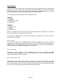
APPENDIX E:Adjusting the CV outputs
If your MAQ is still under warranty the adjustment should be done at the manufacturer
(Doepfer) or an authorized service company. Otherwise you will loose your warranty. We will
send you a list of all authorized service companies upon request. Not correctly adjusted CV
scale is no reason for warranty. If the only „defect“ in a MAQ unit sent for repair is the
incorrect scale this is no matter of warranty.
CV3
CV2
CV1
Page 31
Doepfer
Musikelektronik
www.doepfer.com
© 2001 by Doepfer Musikelektronik
Page 32