1
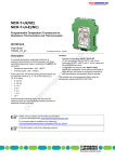
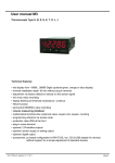
MCR Temperature Measuring Transducer – MCR-T-UI(-E)...
2. Technical Data
OUT
+
-
1
2
3
+
-
NC
NC
ϑ
A
D
D
µC
4
5
6
A
7
8
9
O UT I
O UT U
GND
0
!
"
=
=
114.5
IN
+
-
(+) 24VDC
SP
(–) GND
99
MCR-T-UI(-E)/...
with signal conversion: resistance thermometer
and thermocouple/± 5 V; ± 10 V; 0(1)…5 V; 0…10 V;
0…20 mA; 4…20 mA
8
M3
fixed
Connection data
[mm2]
0.2-2.5
flexible
Housing width 17.5 mm (0.689 in.)
Aa
AWG
0.2-2.5
24-14
Description
MCR-T module, not configured,
for thermocouple sensors and
resistance thermometers,
in 2, 3 or 4-wire technology
0…20 mA, 4…20 mA,
0(1)…5 V, 0…10 V,
± 5 V, ± 10 V
(also inverse signals)
MCR-T module,
as above. Configured version
0…20 mA, 4…20 mA,
0…5 V, 0…10 V, 1...5 V,
± 5 V, ± 10 V
MCR-T module, not configured,
for thermocouple sensors and
resistance thermometers, in 2, 3 or
4-wire technology, with electrical
isolation of input/output and input/power
supply
MCR-T module,
as above. Configured version
0…20 mA, 4…20 mA,
0(1)…5 V, 0…10 V,
± 5 V, ± 10 V
(also inverse signals)
0…20 mA, 4…20 mA,
0…5 V, 0…10 V, 1...5 V,
± 5 V, ± 10 V
Order No.
MCR-T-UI/NC
28 14 10 0
1
MCR-T-UI 1)
28 14 09 0
1
MCR-T-UI-E/NC
28 14 12 6
1
MCR-T-UI-E 1)
28 14 11 3
1
1
) Specify configuration! (See order example on the last page)
Technical Data
Input
Input
Supply current (resistance thermometer)
Input protection
Connection method
Pcs.
Pkt.
Type
Resistance thermometer in 2, 3 or 4-wire technology
Thermocouple sensors (B, E, J, K, N, R, S, T, L, U, C, W, HK)
Linear mV signals from - 20 mV to + 2400 mV
250 µA
Transient protection, surge protection 30 V DC
Plug-in screw-clamp connection
Additional technical data can be found on page 3
PHOENIX CONTACT page 2 of 7