1
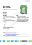
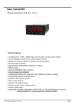
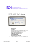
MCR-T-UI(-E)...
MCR Temperature Measuring Transducer
1. Description
A universal temperature measuring transducer for
resistance thermometers and thermocouples, with
freely selectable temperature range, is available for the
MCR-T converters (resistance thermometer: -200°C to
850°C [-328˚F to +1562˚F]), thermocouple sensors:
-200°C to 2300°C [-328˚F to +4172˚F]).
The analog standard signals 0(4)…20 mA, 0…10 V,
±10 V, 0(1)…5 V, ±5 V can be used with normal (e.g.,
0…10 V) and inverse (e.g., 10…0 V) action on the
output side.
A PNP transistor switching output (100 mA) with two
switching points and 8 switching functions provides an
additional monitoring function.
1.1. Versions
• With standard configuration - MCR-T-UI(-E)/NC (PT100 DIN IEC 751 3-wire from -200…850°C
(-328˚F… 1562˚F) with 4…20 mA output and
disabled switching output)
• With project-specific configuration - MCR-T-UI(-E) The configuration should be specified in the order
key (see Page 5). Upon delivery the module is
configured according to user requirements and
therefore ready to operate.
• The modules can be parameterized freely using the
configuration kit MCR-CONF-WIN or MCR/PICONF-WIN.
1.2. Input
The following sensor types and input signals can be
processed on the input side:
• Resistance thermometers in 2, 3 or 4-wire version
• Thermocouple sensors
• Thermocouple sensors of the same type connected
in series for measuring temperature differentials
• mV voltages from -20 mV to +2400 mV
• Linear resistors in the range from 0 Ω to 8000 Ω
• Potentiometers up to 8 kΩ
1.3. Output
The MCR-T… has two outputs:
• Analog output with either 0(4)…20 mA or 0…10 V,
±10 V, 0(1)…5 V, ±5 V with normal or inverse action
(e.g., 0...10 V /10…0 V). The loads must not fall
below a voltage output of 10 kΩ and must not
exceed a current output of 500 Ω.
• PNP transistor switching output (100 mA) without
free-wheeling diode but with suppressor diode for
transient protection. The configuration kit
MCR-CONF-WIN... or MCR/PI-CONF-WIN is
required to program this output.
Headquarters: © Phoenix Contact GmbH & Co. KG • Flachsmarktstraße 8 • 32825 Blomberg • Germany
Phone +49-(0) 52 35-3-00 • Fax +49-(0) 52 35-3-4 12 00 • www.phoenixcontact.com
Local Contact: www.phoenixcontact.com/salesnetwork
MCR Temperature Measuring Transducer – MCR-T-UI(-E)...
2. Technical Data
OUT
+
-
1
2
3
+
-
NC
NC
ϑ
A
D
D
µC
4
5
6
A
7
8
9
O UT I
O UT U
GND
0
!
"
=
=
114.5
IN
+
-
(+) 24VDC
SP
(–) GND
99
MCR-T-UI(-E)/...
with signal conversion: resistance thermometer
and thermocouple/± 5 V; ± 10 V; 0(1)…5 V; 0…10 V;
0…20 mA; 4…20 mA
8
M3
fixed
Connection data
[mm2]
0.2-2.5
flexible
Housing width 17.5 mm (0.689 in.)
Aa
AWG
0.2-2.5
24-14
Description
MCR-T module, not configured,
for thermocouple sensors and
resistance thermometers,
in 2, 3 or 4-wire technology
0…20 mA, 4…20 mA,
0(1)…5 V, 0…10 V,
± 5 V, ± 10 V
(also inverse signals)
MCR-T module,
as above. Configured version
0…20 mA, 4…20 mA,
0…5 V, 0…10 V, 1...5 V,
± 5 V, ± 10 V
MCR-T module, not configured,
for thermocouple sensors and
resistance thermometers, in 2, 3 or
4-wire technology, with electrical
isolation of input/output and input/power
supply
MCR-T module,
as above. Configured version
0…20 mA, 4…20 mA,
0(1)…5 V, 0…10 V,
± 5 V, ± 10 V
(also inverse signals)
0…20 mA, 4…20 mA,
0…5 V, 0…10 V, 1...5 V,
± 5 V, ± 10 V
Order No.
MCR-T-UI/NC
28 14 10 0
1
MCR-T-UI 1)
28 14 09 0
1
MCR-T-UI-E/NC
28 14 12 6
1
MCR-T-UI-E 1)
28 14 11 3
1
1
) Specify configuration! (See order example on the last page)
Technical Data
Input
Input
Supply current (resistance thermometer)
Input protection
Connection method
Pcs.
Pkt.
Type
Resistance thermometer in 2, 3 or 4-wire technology
Thermocouple sensors (B, E, J, K, N, R, S, T, L, U, C, W, HK)
Linear mV signals from - 20 mV to + 2400 mV
250 µA
Transient protection, surge protection 30 V DC
Plug-in screw-clamp connection
Additional technical data can be found on page 3
PHOENIX CONTACT page 2 of 7
MCR Temperature Measuring Transducer – MCR-T-UI(-E)...
Output
Output signal
Maximum output signal
D/A resolution
Load
Ripple
Open-circuit response
Measuring range exceeded/not reached
Output protection
Switching output
General Data
Supply voltage
Current consumption
Transmission error
Cold junction error
Temperature coefficient
Ambient temperature range
Test voltage (only MCR-T-UI-E...)
0…20 mA 4…20 mA 0(1)…5 V 0…10 V ± 5 V
± 10 V
24 mA
24 mA
±12 V
±12 V ±12 V ± 12 V
± 12 bits
≤ 500 Ω ≤ 500 Ω ≥ 10 kΩ ≥ 10 kΩ ≥ 10 kΩ ≥ 10 kΩ
< 20 mVpp
From - 12 V to + 12 V or 0 mA to 24 mA
From - 12 V to + 12 V or 0 mA to 24 mA
Transient protection
PNP transistor output, with a load capacity of 100 mA, switches supply
voltage; disabled for project-specific configuration, otherwise can be
freely programmed using MCR-CONF-WIN-... and MCR/PI-CONFWIN.
Input/output
Input/power supply
Approbation
c
18...30 V DC
≤ 60 mA
≤ 0.1% of the final value, + 6 mV or 12 µA at the output
≤ 3 K, typical 1.5 K
≤ 0.01%/K, typical 0.005%/K
- 20°C to + 65°C (-4˚F to 149˚F)
1 kV, 50 Hz, 1 minute
1 kV, 50 Hz, 1 minute
F
Conforms to the EMC Directive 89/336/EEC and the
Low Voltage Directive 73/23/EEC
EMC (electromagnetic compatibility)
Noise immunity according to 50082-2
• Electrostatic discharge (ESD)
8 kV air discharge2)
4 kV contact discharge2)
EN 61000-4-2
• Electromagnetic HF field
Amplitude modulation
Pulse modulation
EN 61000-4-3
• Fast transients (burst)
EN 61000-4-4
Input/output/supply:
2 kV/5 kHz2)
• Conducted interference
EN 61000-4-6
Input/output/supply:
10 V1)
Noise emission according to EN 50081-2
EN 55011
Class A
EN 61000 corresponds to IEC 1000/
EN 55011 corresponds to CISPR22
These results were achieved using shielded cables.
1)
2)
10 V/m1)
10 V/m1)
Criterion A: normal operating characteristics within the specified
limits.
Criterion B: temporary adverse effects on the operating
characteristics which the device corrects itself.
Class A:
industrial application without special
installation measures
1
6
O
4V
P
+2
I
U
R ND
E G
WP
D
S T GN
U
O
I
T/U
RMC
2
r
we
Po
de
Mo
1
2
4
IN
MCR-T-UI ... MCR Temperature Measuring
Transducer
N
3
C
N
C
1 Programming interface
1
0
I 4 09
T/U 1
R- : 28
MC.-Nr.
Art
7
T
OU
2
3
8
2 Plug-in screw-clamp terminals (COMBICON)
D A
3
3 Shield connection (on terminal 5 or 6)
5
IN
6
ϑ
2
=
4
5
6
4 Metal lock for fastening on the DIN rail
1
2
3
6 Error LED
11
12
D
1
3
5 Plug-in screw-clamp terminals (COMBICON)
9
10
µC
4
4
.
/
N.C
N
.
NE
N.C ATIO
6
OB
PR
AP
=
7
I
8
T
OU
U
T
9
OU
10
D
DC
GN
V
11
4
+2
12
SP
D
GN
LS
A
OV
PR
AP
5
4
PHOENIX CONTACT page 3 of 7
5
MCR Temperature Measuring Transducer – MCR-T-UI(-E)...
3. Method of Operation
The analog input signal of the temperature sensor is
digitized with a 24-bit resolution and then supplied to a
microcontroller. The microcontroller forms a digital
output value in line with the temperature from the input
signal. This is supplied via optocouplers to a D/A
converter after electrical isolation. The corresponding
output signals are realized using a subsequent voltage
or current level (e.g., 0…10 V, 0…20 mA).
The microcontroller has an integrated memory in
which the program sequence for the measured value
calculation is stored. The user-specific parameters are
stored in an EEPROM (electrically erasable
programmable read-only memory). The programmed
data remains in the memory even after the supply
voltage has been disconnected.
4. Connections
4.1. Thermocouple Sensors
• Simple temperature measurement
For temperature measurement using the
thermocouple sensors described on page 5, the
terminal points 1 and 2 of the MCR-T should be
connected taking into consideration the polarity of
the sensor.
(1 = "+" input; 2 = "–" input)
• Differential temperature measurement
To measure temperature differentials with only one
temperature measurement converter, the
MCR-T… offers the option of connecting two
thermocouple sensors of the same type in series and
laying the two remaining branches to terminal points
1 and 2. The connection ends of the two
thermocouple sensors can be fixed to terminal points
5 and 6 (see corresponding circuit diagram). The
differential temperature measurement can only be
set using the configuration software MCR-CONFWIN… or MCR/PI-CONF-WIN because the internal
cold junction compensation must be switched off for
this.
4.2. Resistance Thermometer
For temperature measurement using the resistance
thermometers described on page 5, the terminal points
must be connected according to the wire connection
method (see corresponding circuit diagram); 1 and 3
for 2-wire, 1, 2 and 3 for 3-wire and 1, 2, 3 and 4
for 4-wire technology.
4.5. Evaluation of Potentiometer Settings
To evaluate potentiometers up to 8 kΩ, terminals 1
and 3 are connected with the external cables and
terminal 2 is connected 2 with the loop cable.
4.6. Switching Output
The PNP transistor switching output switches the
supply voltage UB when the programmed switching
conditions are met from 24 V on terminal !. The
transistor output should only be loaded with a
maximum of 100 mA.
A suppressor diode protects this output from fast
transients.
5. Error Detection:
Open Circuit/Measuring Range Exceeded or
Not Reached
Display of open circuit/measuring range exceeded or
not reached for project-specific configured
modules:
• The red MODE LED is permanently on.
• The following voltages and currents can be measured
at the output using the selected output signal
configuration:
Output Signal at
Output Signal
Open Circuit
Measuring Range
Exceeded/
Not Reached
0...5 V; ±5 V
0...10 V; ±10 V
0...20 mA
4...20 mA
5.5 V
11 V
22 mA
22 mA
5.25 V
10.5 V
21 mA
21 mA
During independent configuration, values between
-12…+12 V and 0…24 mA can be set freely.
6. Changing the Configuration Data
To change the configuration data, use the
configuration kit MCR-CONF-WIN… or MCR/PICONF-WIN. An additional User Manual and online
help for the software provide a more detailed
explanation of the configuration options and how to
carry them out.
The adapter cable MCR-TTL/RS232-E should be
used to connect the module and the PC. This is not
contained in the configuration kit.
4.3. Measurement of mV Voltages
Voltages in the range from -20…+2400 mV are
measured at terminal points 1 and 2, where 1 is the
"+" input and 2 is the "–" input.
4.4. Measurement of Resistance
To measure differing resistance between 0…8000 Ω,
terminal points 1 and 3 are used. The connection is
made using 2-wire technology.
PHOENIX CONTACT page 4 of 7
MCR Temperature Measuring Transducer – MCR-T-UI(-E)...
7. Order Key for the Programmable Temperature Measuring Transducer
Resistance Thermometer
Thermocoup es
(Temperature Ranges According to IEC 751/EN 60 751 and DIN 43
760 SAMA RC 21-4-1966 in 2, 3 or 4-Wire Version)
Sensor Type
1)
Measuring
Range
Standard
Minimum
Measuring
Range Span
Pt sensors
Ni sensors
Cu sensors
Ni 1000
Cu 50
Cu 53
KTY 81-110
-200°C...850°C
-60°C...180°C
-70°C...500°C
-50°C...160°C
-50°C...200°C
-50°C...180°C
-55°C...150°C
(DIN/SAMA)
(DIN/SAMA)
(SAMA)
(Landis & Gyr)
–
–
(Philips)
0.4 K
0.4 K
0.4 K
0.4 K
0.4 K
0.4 K
0.4 K
1
Sensor Type
1
)
Thermocouple
Measuring
Range
Minimum
Measuring
Range Span
U 2)
T 2)
L 2)
J 2)
E 2)
K 2)
N 2)
S 2)
R 2)
B 2)
Cu-CuNi
Cu-CuNi
Fe-CuNi
Fe-CuNi
NiCr-CuNi
NiCr-Ni
NiCrSi-NiSi
Pt10Rh-Pt
Pt13Rh-Pt
Pt30RhPt6Rh
-200°C...600°C
-200°C...400°C
-200°C...900°C
-210°C...1200°C
-226°C...900°C
-200°C...1372°C
-200°C...1300°C
-50°C...1768°C
-50°C...1768°C
500°C...1820°C
>1K
>1K
>1K
>1K
>1K
>1K
>1K
>4K
>4K
> 10 K
-18°C...2316°C
-18°C...2316°C
-200°C...800°C
>4K
>4K
>1K
C
W
HK
) Additional types or characteristics on request.
Equation to convert temperatures from°C to °F:
9
T [°F] = – T [°C] + 32
5
2
) Thermocouples according to IEC 584/EN 60584
Resistors, Potentiometers, mV Vo tages
Input
Measuring Range
Order
Minimum
Reference Measuring
Range Span
Resistor
0 Ω … 8000 Ω
(2-wire)
RES
2Ω
Potentiometer
(max. 8 kΩ)
0 … 100%
(3-wire)
POT
0.2%
Voltage
-20 mV …+2400 mV VOL
2 mV
Order Key for MCR-T-UI-E (Order No. 28 14 11 3) and MCR-T-UI (Order No. 28 14 09 0)
The standard configuration will be supplied if customer order details are incorrect or not provided.
Sensor Type
Characteristic
Connection
Measuring
Standard configuration:
MCR-T-UI-E
/ PT100
/ D
/ 3
See tables
above under
"Sensor Type"
and "Order
Reference"
D = DIN
S = SAMA
(see above table)
0 = for thermocouple,
resistor,
potentiometer,
voltage, Ni1000
(Landis&Gyr)Cu 10,
KTY 81-110, Cu50,
Cu53
Measuring Unit
Output
1
/ 2
1 =°C
2 = °F
3 = mV
4=Ω
5=%
0 = 0…10 V
1=0…5V
2 = 0…20 mA
3 = 4…20 mA
4 = -10…+10 V
5 = -5 … +5 V
/ -200.0
2 = 2-wire
3 = 3-wire
4 = 4-wire
0 = for
thermocouple,
resistor,
potentiometer,
voltage,
Start value
at 0 mA
(e.g., -200.0°C
[-328˚F])
Output
Characteristic
/ 1
1 = normal
2 = inverse
PHOENIX CONTACT page 5 of 7
/ +850.0
Final value
at 20 mA
(e.g., +850.0°C
[+1562˚F)
/
MCR Temperature Measuring Transducer – MCR-T-UI(-E)...
Order Examples for MCR-T-UI(-E) With Different Input Versions:
Resistance Thermometer
MCR-T-UI-E
/ PT100
/ D
3
/ -200.0
/ +850.0
/ 1
/ 3
/ 1
(Configuration for 3-wire PT100 sensor: according to DIN of -200.0°C to +850.0°C with 4…20 mA output
characteristic)
Thermocouple
MCR-T-UI-E
/ J
/ 0
/ 0
/ -346
/ +2192
/ 2
/ 3
/ 2
(Configuration for thermocouple Type J from -346°F to +2192°F with 20…4 mA output characteristic)
Voltage
MCR-T-UI-E
/ VOL
/ 0
/ 0
/ -10
/ 1200
/ 3
/ 0
/ 2
(Configuration for voltage input from -10 mV to +1200 mV with 10…0 V output characteristic)
Resistor (2-wire connection)
MCR-T-UI-E
/ RES
/ 0
/ 0
/ 0
/ 7500
/ 4
/ 1
1
(Configuration to connect a resistor that varies between 0 Ω and 7500 Ω. The output signal is 0…5 V.)
Potentiometer (3-wire connection)
MCR-T-UI-E
/ POT
/ 0
/ 0
/ 10
/ 90
/ 5
/ 3
/ 1
(Configuration for connecting a 3-wire potentiometer, where 10 - 90% of the range is used.
The output is 4…20 mA.)
8. Application Example
Temperature monitoring with a PT100 element in 2-wire technology
when using the transistor switching output
50°C
PT 100
0°
C
0°
C
10
Cooler
IN
1
4
6
NC
3
Pow er
2
OUT
M CR - T - UI - E
Mode
5
NC
POWER
I
7
U
8
GND
9
+ 24V
SP
GND
0
!
"
Alarm
24V
Line voltage
PHOENIX CONTACT page 6 of 7
MCR Temperature Measuring Transducer – MCR-T-UI(-E)...
9. Connection Examples
Application;
• For short distances and slow changes.
Please note:
• The cable resistances RL1 and RL2 directly affect
the measuring result and make it incorrect.
Compensation of ± 5% is possible.
RL2
Mode Power
3
7 10
+24 V DC
GND
9 12
OUT I
GND
Output: current signal 0(4)…20 mA
RL1
MCR-T-UI-E
1
ϑ
10
8
2
RL2
Mode Power
3
+24 V DC
GND
9 12
OUT U
GND
RL3
Output: voltage signal 0(1)…(5)10 V, ±(5)10 V
RL1
4
RL2
RL3
ϑ
MCR-T-UI-E
1
10
11
2
Mode Power
3
+24 V DC
GND
9 12
SP
RL4
Additional switching output
Potentiometer
http://www.phoenixcontact.com
Application;
• For longer distances between the PT 100 sensor
and the MCR module and varied cable resistances
(RL1 ≠ RL2 ≠ RL3 ≠ RL4)
Please note:
• The cable resistance (RL2 + RL4) should not exceed
50 Ω.
MCR-T-UI-E
1
R, ϑ
RL1
MCR-T-UI-E
1
7 10
2
Mode Power
3
+24 V DC
GND
9 12
OUT I
GND
RL2
Application;
• Connection of a thermocouple or an mV signal.
mV / TC
1
+
–
MCR-T-UI-E
7 10
2
Mode Power
+24 V DC
GND
9 12
February 15, 2000
OUT I
GND
TNR: 5087219-02
Application;
• For longer distances between PT 100 sensor and
the MCR module (RL1, RL2, RL3 ≤ 25 Ω)
Please note:
• To compensate the cable resistance, all cable
resistances must have exactly the same values
(RL1 = RL2 = RL3)
RL1
Application;
• Differential temperature measurement using
thermocouples.
TC
TC
+
-
1
+
-
MCR-T-UI-E
7 10
2
6
Mode Power
+24 V DC
GND
9 12
OUT I
GND
PHOENIX CONTACT page 7 of 7
∀ PHOENIX CONTACT
Application;
• For short distances (< 10 m [32.808 ft.])
Please note:
• The cable resistances RL1 and RL2 directly affect
the measuring result and make it incorrect
(example for PT100: 0.385 Ω = 1 K).
Compensation of ± 5% is possible.