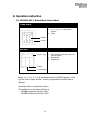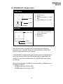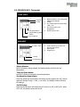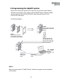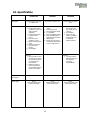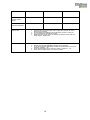
1
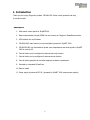
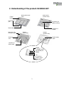
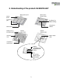
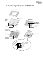
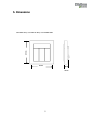
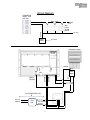
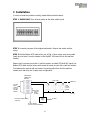
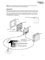
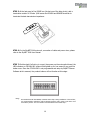
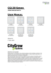
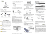
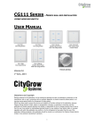
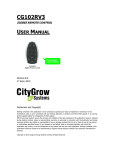
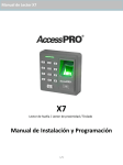
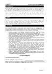
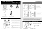
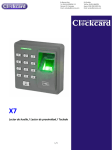
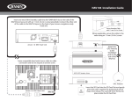
CG100H-SKY SERIES
SKYNET 2000 CONTROL PANEL
USER MANUAL
CG100HHB-SKY
Doorbell Switch
CG100H4-SKY
4 Button Mood Control Panel
CG100HTH-SKY
Thermostat
VERSION 02
30 JAN, 2015
Disclaimers and Copyright
Nothing contained in this publication is to be construed as granting any right, by implication or otherwise, for the
manufacture, sale, or use in connection with any method, apparatus, or product covered by letters patent, or as insuring
anyone against liability for infringement of letters patent.
Efforts have been made to ensure the accuracy and reliability of the data contained in this publication; however, Citygrow
Energy Systems Limited. makes no representation, warranty, or guarantee in connection with this publication and hereby
expressly disclaims any liability or responsibility for loss or damage resulting from its use or from the use of any product
or methodology described herein; for any violation of any federal, state, or municipal regulation with which this
publication may conflict; or for the infringement of any patent from the use of this publication. Nothing contained in this
publication should be viewed as an endorsement by Citygrow Energy Systems Limited. of any particular manufacturer’s
products.
Copyright © 2012 Citygrow Energy Systems Limited, All Rights Reserved
CAUTION
RISK OF ELECTRIC SHOCK DO NOT OPEN
CAUTION: TO REDUCE THE RISK OF ELECTRIC SHOCK,
DO NOT REMOVE COVER (OR BACK) NO USER-SERVICEABLE
PARTS INSIDE REFER SERVICING TO QUALIFIED SERVICE PERSONNEL
The lightning flash with arrowhead symbol within an equilateral triangle is intended to alert the user
to the presence of uninsulated “dangerous voltage” within the product’s enclosure that may be of
sufficient magnitude to constitute a risk of electric shock to persons.
The exclamation point within an equilateral triangle is intended to alert the user to the presence of
important operating and maintenance (servicing) instructions in the literature accompanying the
product.
IMPORTANT SAFETY INSTRUCTIONS
READ BEFORE OPERATING EQUIPMENT
This product was designed and manufactured to meet strict quality and safety standards.
There are, however, some installation and operation precautions which you should be particularly aware of.
1.
2.
3.
4.
5.
6.
7.
8.
9.
10.
11.
12.
13.
14.
Read these instructions.
Keep these instructions.
Heed all warnings.
Follow all instructions.
Do not use this apparatus near water.
Clean only with dry cloth.
Do not block any ventilation openings. Install in accordance with the manufacturer’s instructions.
Do not install near any heat sources such as radiators, heat registers, stoves, or other apparatus that produce heat.
Do not defeat the safety purpose of the polarized or grounding-type plug. If the provided plug does not fit into your
outlet, consult an electrician for replacement of the outlet.
Protect the power cord from being walked on or pinched particularly at plugs, convenience receptacles, and the point
where they exit from the apparatus.
Only use attachments/accessories specified by the manufacturer.
Use only with the cart, stand, tripod, bracket, or table specified by the manufacturer, or sold with the apparatus. When
a cart is used, use caution when moving the cart/apparatus combination to avoid injury from tip-over.
Unplug this apparatus during lightning storms.
Refer all servicing to qualified service personnel. Servicing is required when the apparatus has been damaged in any
way, such as power-supply cord or plug is damaged, liquid has been spilled or objects have fallen into the apparatus,
the apparatus has been exposed to rain or moisture, does not operate normally, or has been dropped.
Table of Content
1. Introduction ........................................................................................................ 1
2. Understanding of the product-CG100H4-SKY .......................................................... 2
3. Understanding of the product-CG100HTH-SKY........................................................ 3
4. Understanding of the product-CG100HHB-SKY........................................................ 4
5. Dimensions ......................................................................................................... 5
6. Wiring ................................................................................................................. 6
7. Installation .......................................................................................................... 8
8. Operation instruction.......................................................................................... 11
8.1 CG100H4-SKY, 4 Button Mood Control Panel ...................................................... 11
8.2 CG100HHB-SKY, Doorbell switch ....................................................................... 12
8.3 CG100HTH-SKY, Thermostat ............................................................................. 13
9.Programming the SkyNET system ......................................................................... 14
10. Specification .................................................................................................... 15
1. Introduction
Thank you for buying Citygrow’s product. CG100H-SKY Series is both powerful and easy
to use and install.
Description
1. Wall mount control panel for SkyNET2000
2. Data communicates through RS485 bus and running on Citygrow’s SmartBus protocols.
3. LED indicator for on/off status.
4. CG100H4-SKY main function is to preset lighting scenes for SkyNET 2000.
5. CG100HTH-SKY is a thermostat to preset room temperature and send signals to SkyNET
2000 to control A/C.
6. Control button can be configured to become two way function.
7. Control button can be configured to become scene function.
8. Control button graphics can be tailor-made per customer requirement.
9. Mounted in a standard UK wall box.
10. Easy to install.
11. Power supply by external DC12V. (powered by SkyNET 2000 system power supply)
1
2. Understanding of the product-CG100H4-SKY
Control
button
Button panel
(bottom view)
Button panel (front
view)
Programming
port
Dip Switch (for
address setting)
Reset button
Metal clip to fix
the button panel
Connector to
Bracket
Bracket
(front view)
Bracket
(bottom view)
Mounting
hole
Model number
plate
Connector to
button panel
RS485B
To SkyNET control
panel RS485 port
RS485A
12V DC 12V from
SkyNET system
power supply
12V +
2
3. Understanding of the product-CG100HTH-SKY
Control
button
Button panel (front
view)
Button panel
(bottom view)
Programming
port
Dip Switch (for
address setting)
Connector to
Bracket
Reset button
Metal clip to fix
the button panel
Bracket
(front view)
Bracket
(bottom view)
Model number
plate
Mounting
hole
Connector to
button panel
RS485B
To SkyNET control
panel RS485 port
RS485A
12V DC 12V from
SkyNET system
power supply
12V +
3
4. Understanding of the product-CG100HHB-SKY
Frame
Doorbell
button
Button panel (front
view)
Button panel
(bottom view)
Programming
port
Dip Switch (for
address setting)
Connector to
Bracket
Reset button
Metal clip to fix
the button panel
Bracket
(front view)
Bracket
(bottom view)
Mounting
hole
Model number
plate
Connector to
button panel
BELL- , dry contact,
max. 1A, 24Vac/dc
BELL+
RS485B
RS485A
12V 12V +
4
5. Dimensions
85mm
CG100H4-SKY, CG100HTH-SKY, CG100HHB-SKY
85mm
28mm
5
6. Wiring
Before getting started
WARNING! It must be installed by a qualified electrician in accordance with all applicable regulations
and building codes. Improper wiring can result in personal injury or damage to control units or other
equipment. Always turn off circuit breaker or remove main fuse from power line before doing any work.
To avoid overheating and possible damage to equipment.
WARNING! Do not operate when any lamps removed or burned out; replace any burned out lamps
immediately; use only transformers that incorporate thermal protection or fused primary windings. ! This
product is designed for residential and commercial use, for indoor use only.
WARNING! Install in accordance with all national and local electrical codes.
IMPORTANT! Citygrow® is not liable for any damage incurred with the misuse of this
product.
6
Wiring Diagram
CG801SKN-M
SkyNET 2000
Main Unit
Daisy chain
RS485
bus
Wall
mount
control
panels
DC 12V
DC 12V
Power
supply
AC 220V
Distribution board
Neutral
Live
For CG100HHB-SKY only
AC Live
Neutral
Door
Bell
Dry contact
control
7
0V
12V +
Neutral
(System)
RS485B
RS485A
Power
supply
7. Installation
In order to install the product correctly, please follow the below steps:
STEP 1: IMPORTANT! Turn off main power at the main switch board.
STEP 2: Loosen the screws of the original wall switch. Remove the switch and the
wiring.
STEP 3: Pull the Belden 8723 cable and 1 pair of Dia. 1.5mm copper wire power cable
(black and red color) from the location of the SkyNET 2000 main unit to the wall box
location.
Please note if you have more than 1 wall box location to install CG100H4-SKY panel, the
Belden 8723 cable and the power cable should be ready at each of the wall box location.
The cables at the second wall box location should be pulled from the first wall box
location such that they are in daisy chain configuration.
CG801SKN-M
SkyNET 2000
Main Unit
Daisy chain
To Loads
-lamps
-curtains
-fan coils
are NOT
allowed
To LAN (for central control)
- Optional
Wall
mount
control
panels
DC 12V
To Loads
-fan coils
-lamps
-curtains
RS485 bus
DC 12V
Power
supply
AC 220V
AC 220V Neutral
(for Zero crossing detection)
8
STEP 4: Connect the Belden 8723 cable wires and the power wires, and then fix the
product on the wall box according to the following diagram.
Important!
Before plugging the Button panel onto the Bracket, double check the Dip Switch located
at the back of the Button panel to see whether the address is equal to the label located
at the front of the button panel. If there is no address label at the front of the Button
panel, please add an address label to it. This address label will be for future use during
the SkyNET Planner programming.
Address label
Frame
Button panel
Bracket
Screw x 4 pcs
Screw x 2 pcs
wall box
BELLBELL+
(From doorbell, for
CG100HHB-SKY), dry contact
Max. 1A, 24Vdc/ac
RS485B (From Belden 8723, Green)
RS485A (From Belden 8723, White)
12V - (From power cable “Black”)
12V + (From power cable “Red”)
9
STEP 5: At the last panel of the RS485 bus (the last one of the daisy chain), add a
termination resistor of 120ohm 1/4W across the RS485A and RS485B terminals to
terminate the data transmission impedance.
STEP 6: For the SkyNET 2000 main unit, connection of cable and power wires, please
refer to the SkyNET 2000 User Manual.
STEP 7: Double check if all wiring is correct, then power up the main switch board, the
LED indicators on CG100H-SKY series will be lighted up for one second if you push the
button once. Since the CG100H-SKY is not programmed and setup by SkyNET Planner
Software at this moment, the product buttons will not function at this stage.
Notes:
•
Use standard UK wall box BS4662; minimum 35mm deep. During installation of the wall box,
it is recommended to embed the wall box deeper inside the wall in order to give more room
to install the product. The room inside is recommended to have 50mm deep.
10
8. Operation instruction
8.1 CG100H4-SKY, 4 Button Mood Control Panel
COVER PLATE
1
3
1. 1, 2, 4, 4, 5, 6, 7, 8 are buttons
location.
2. Frame
2
5
7
1. Button
4
6
8
2. Frame
MAIN UNIT
3. Lock x 4 pcs
3. 4 pcs Locks to fix the main unit onto
the wall bracket.
4. Reset button
5. Program port
4. Reset
5. Program port
Button 1, 2, 3, 4, 5, 6, 7, 8 can be programmed to be ON/OFF function, or Dim
up/ Dim Down or Scene function. It can be programmed via SkyNET Planner
Software.
Push these button to activate the function.
The backlit icons on the button will light up
- LED ON indicates the Function is ON.
- LED OFF indicates the Function is OFF.
11
8.2 CG100HHB-SKY, Doorbell switch
COVER PLATE
1. Button
1. Doorbell button.
2. Frame.
3. Clean Room Indicator ( For Hotel
Only)
4. Do Not Disturb ( For Hotel Only)
2. Frame
4. Do Not
3. Clean Room
Disturb
MAIN UNIT
5. Lock x 4 pcs
5. 4 pcs Locks to fix the main unit
onto the wall bracket.
6. Reset button
7. Program port
6. Reset
7. Program port
When Doorbell button is pressed, the dry contact output for bell will be
momentary on for 1 seconds, during this 1 second duration, the bell will be
driven on and doorbell will ring for 1 second.
If CG100HHB-SKY is selected to be used for hotel project, see diagram above,
the Do Not Disturb or Clean Room LED indicator cab be programmed to be
switched on when the preselected button on a CG100H4-SKY panel is being
pressed down.
Push the Doorbell button to activate the doorbell function, the backlit icons on
the button will light up
- LED ON indicates the Function is ON.
- LED OFF indicates the Function is OFF.
12
8.3 CG100HTH-SKY, Thermostat
COVER PLATE
1. Display
2. Frame
3. Fan Speed button
4. Temperature Up/Down
button.
5. On/ Off button
1. Display window to show temperate
readings and settings.
2. Frame
3. Up / Down control fan speed High
/ Mid / Low
4. Up/ Down preset room
temperature
5. On/off control of A/C
MAIN UNIT
6. Lock x 4 pcs
6. 4 pcs Locks to fix the main unit
onto the wall bracket.
7. Reset button
8. Program port
7. Reset
8. Program port
Display Window:
When no button is being pressed, the display window will show the set
temperature.
Temp Up/Down button:
Press Up or Down to change the preset temperature.
Fan Speed Up/Down button:
Press Fan Speed Up/ Down button will change the fan speed of the A/C, the fan
speed will change in High -> Mid -> Low order. The display window will show
the settings.
On/Off button:
Press the On/Off button will switch the A/C from On to Off, or Off to On. When
A/C is off, the display window will be off.
13
9. Programming the SkyNET system
Remove one of the button panel from the wall, then you will see the wall bracket is
still fixed on the wall box. Then prepare a PC with SkyNET Planner Software installed
and run it with the CG101UT5 and CG100UTC cable connected from PC to the
CG101TP-SKY Tools Panel.
See following diagram….
STEP 2
Plug the CG101TP-SKY
Tools Panel on the wall
bracket.
STEP 1
Select “one of the wall
mount panel” and remove
the frame and the keypad.
CG101UT5
USB to 5 pin
conversion
cable
STEP 3
Connect CG101UTU
and CG101UT5 cable
from the PC to the 5 pin
connector of CG101TPSKY Tools panel.
CG101UTC
USB to COM conversion
cable
PC installed
with SkyNET
Planner
Software and
run it.
STEP 4
Refer to the user manual of “SkyNET Planner” Software to program and set the address
of the product.
14
10. Specification
CG100H4-SKY
CG100HTH
CG100HHB
Description
4 button mood control panel
for SkyNET 2000
Thermostat for SkyNET 2000
Doorbell switch for SkyNET
2000
Function
1. 8 preset lighting scenes.
2. Lighting scenes is able
to include IR control. (IR
device purchase
separately)
3. Lighting scenes is able
to include curtain
control.
4. Max. 150 devices
included in a scene.
5. Minimum dimming level
preset.
6. Memory dim function.
7. Two way control
function.
8. LED backlight.
1. High, Mid, Low, cool, heat
control.
2. Temperature preset.
3. Room temperature display.
4. C /F selectable.
5. Built-in temperature sensor.
6. Work with CG801SW8 to
implement fan coil Control.
7. LED backlight.
8. Support two way function,
ie multiple CG100HTH-SKY
control of single Fan Coil.
1. Build-in contactor to
drive AC door bell.
Dry contact max. 1A,
24Vdc/ac.
2. LED backlight
3. Support two way
function, ie different
doorbell switch can
be located at
different locations.
Remarks:
1. When up button is used
for dimming up function,
the down button cannot
be programmed as
scene function.
2. Maximum number of
devices programmed
into the whole product is
limited to 150 devices.
Maximum current
consumption
Power supply
Remarks:
1. For hotel customer,
DND and Clean room
LED indicator is
provided on
CG100HHB-SKY.
200mA max.
200mA max.
200mA max.
DC12V
Powered by SkyNET 2000
system power supply
DC12V
Powered by SkyNET 2000
system power supply
DC12V
Powered by SkyNET 2000
system power supply
15
Dimensions mm
(Length x Width x
Depth )
Recommended
operation temperature
RS485 A & RS485B to
SkyNET 2000
CG100H4-SKY
CG100HTH
CG100HHB
85x85x28
85x85x28
85x85x28
0 to 40 degC
0 to 40 degC
0 to 40 degC
1.
2.
3.
4.
Address setting
1.
2.
3.
4.
5.
Panels should be connected in daisy chain configuration. Maximum 32 control
panels can be connected.
Connect RS485 A and RS485 B to the corresponding connector in Main unit.
It is recommended to use Belden 8723 cable.
RS485 terminator 120ohm resistor is needed to be added to end the cable. See
wiring diagram – SkyNET 2000.
Dip switch 1 to 8 for setting the panel address.
Normally, the main unit CG801SKN-M should be set to 00000000.
In case Circuit Extender CG801SKN-E is added, the Circuit Extender can be set to
00000001, 00000010……etc.
Control panel addresses can be 00000100, 00000111, 00000101……etc..
Please refer the SkyNET Planner user manual for details.
16