1
Table of Contents
FAILURE TO FOLLOW THESE INSTRUCTIONS COULD RESULT IN DEATH OR SERIOUS INJURY............................... 2
Do Not Hi-Pot Test SPDs.............................................................................................................................................................................2
INTRODUCTION.................................................................................................................................................... 1
Warning and Safety Information................................................................................................................................................................1
Qualified Person........................................................................................................................................................................................1
Danger......................................................................................................................................................................................................1
Warning....................................................................................................................................................................................................1
Caution.....................................................................................................................................................................................................1
Do Not Hi-Pot Test SPDs.............................................................................................................................................................................1
Limited Warranty.......................................................................................................................................................................................1
Unpacking and Preliminary Inspection.......................................................................................................................................................1
Storage.....................................................................................................................................................................................................1
GENERAL INFORMATION..................................................................................................................................... 2
Product Family Outline .............................................................................................................................................................................2
Type 1 SPD................................................................................................................................................................................................2
Internal Protection.....................................................................................................................................................................................2
Service Guidelines.....................................................................................................................................................................................2
Simplified Explanation of Operation...........................................................................................................................................................2
Industry Standards Changes - 2009...........................................................................................................................................................2
Parallel Connection...................................................................................................................................................................................4
Precautionary Statement Regarding SPDs on Ungrounded Systems.............................................................................................................4
Cascade Surge Protection..........................................................................................................................................................................4
Unpacking & Preliminary Inspection...........................................................................................................................................................4
PRE-INSTALLATION AND PLANNING.................................................................................................................... 4
Operating Environment.............................................................................................................................................................................4
Line Side versus Load Side Installation.......................................................................................................................................................4
Audible Noise ...........................................................................................................................................................................................4
Mounting, Dimensions, and Weight...........................................................................................................................................................4
Service Clearance......................................................................................................................................................................................5
Lead Lengths & Maximizing SPD Performance............................................................................................................................................5
Shortest Leads Possible.............................................................................................................................................................................5
Voltage Rating...........................................................................................................................................................................................5
Circuit Breaker and Disconnect Switch.......................................................................................................................................................5
Terminals..................................................................................................................................................................................................6
Wire Size and Installation Torque...............................................................................................................................................................6
System Grounding.....................................................................................................................................................................................6
NEMA 3R Drain Holes for Standard Steel Enclosure.....................................................................................................................................6
Optional Flush Mount Installation Considerations......................................................................................................................................7
Retro-fit to an Existing Panel with No Available Breaker Positions................................................................................................................7
Disconnect Switch (Opt. on TPS3 12, Std. on TPS3 15)...............................................................................................................................7
UL 1283 required language concerning the installation of EMI Filters.........................................................................................................7
TPS3 12 AND TPS3 15 INSTALLATION INSTRUCTIONS ......................................................................................... 8
OPERATION........................................................................................................................................................ 10
Surge Counter Reset: (if equipped) Resets optional surge counter to zero (0) ..........................................................................................10
Diagnostic Display Panel..........................................................................................................................................................................10
Surge Counter Option..............................................................................................................................................................................10
Dry Contact Option.................................................................................................................................................................................11
Remote Monitor Accessory......................................................................................................................................................................11
MAINTENANCE.................................................................................................................................................. 11
Troubleshooting & Service.......................................................................................................................................................................11
Module Replacement & Service...............................................................................................................................................................11
Display Replacement...............................................................................................................................................................................12
TPS3 15 Series with two modules............................................................................................................................................................12
Technical Support....................................................................................................................................................................................12
Figures
Figure 1: SPD Types..................................................................................................................................................................................2
Figure 2: Typical Parallel Connected SPD on Electrical Panel.......................................................................................................................4
Figure 3: NEMA 3R Drain Holes.................................................................................................................................................................6
Figure 7: Rotating Module........................................................................................................................................................................6
Figure 6: Flush Mount Installation.............................................................................................................................................................7
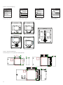
Figure 3: Panel Installation ......................................................................................................................................................................8
Figure 4: Electrical Drawings.....................................................................................................................................................................9
Figure 5: Mechanical Drawings.................................................................................................................................................................9
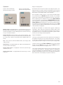
Figure 8: Horizontal Display ...................................................................................................................................................................10
Figure 9: Vertical Display........................................................................................................................................................................10
Figure 10: Dry Contact Connection Configuration...................................................................................................................................11
Tables
Table 1: Model Number Decoder...............................................................................................................................................................3
Table 2: Weight & Dimensions..................................................................................................................................................................5
3