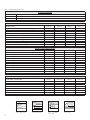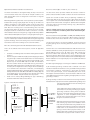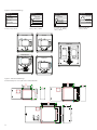
1
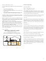
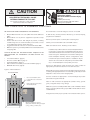
TPS3 12 & TPS3 15
Surge Protective Device
User Manual - USA
V WARNING - Hazardous Voltage & Shock Hazard
Failure to Follow These Instructions Could Result in Death or Serious Injury
•
•
•
•
•
•
Only qualified licensed electricians should install or service SPDs
Hazardous voltages exist within SPDs
SPDs should never be installed or serviced when energized
Use appropriate safety precautions including Personal Protection Equipment
Failure to follow these instructions can result in death, serious injury, and/or equipment damage.
This manual shall be read in entirety prior to installing
Bonding and Grounding Hazard
Verify that the neutral conductor in the service entrance equipment is bonded to ground in accordance with the National
Electrical Code (NEC®) and all applicable codes.
Verify that the neutral terminal (XO) on the secondary side of distribution transformers are grounded to the system ground
in accordance with the NEC® and all applicable codes.
During installation into an electrical system the SPD must not be energized until the electrical system is completely installed,
inspected and tested. All conductors must be connected and functional including the neutral (if required). The voltage
rating of the SPD and system must be verified before energizing the SPD.
Failure to follow these guidelines can lead to abnormally high voltages at the SPD. This may cause the SPD to fail. The
warranty is voided if the SPD is incorrectly installed and/or if the neutral conductor in the service entrance equipment or
downstream of separately derived systems is not bonded to ground in accordance with the NEC®.
Do Not Hi-Pot Test SPDs
Any factory or on-site testing of power distribution equipment that exceeds normal operating voltage such as
high-potential insulation testing, or any other tests where the suppression components will be subjected to higher voltage
than their rated Maximum Continuous Operating Voltage (MCOV) must be conducted with the SPD disconnected from the
power source. For 4-wire systems, the neutral connection at the SPD must also be disconnected prior to performing highpotential testing and then reconnected after test completion.
Failure to disconnect SPD and associated components during elevated voltage testing will damage the SPD and will void
the warranty.
2
Table of Contents
FAILURE TO FOLLOW THESE INSTRUCTIONS COULD RESULT IN DEATH OR SERIOUS INJURY............................... 2
Do Not Hi-Pot Test SPDs.............................................................................................................................................................................2
INTRODUCTION.................................................................................................................................................... 1
Warning and Safety Information................................................................................................................................................................1
Qualified Person........................................................................................................................................................................................1
Danger......................................................................................................................................................................................................1
Warning....................................................................................................................................................................................................1
Caution.....................................................................................................................................................................................................1
Do Not Hi-Pot Test SPDs.............................................................................................................................................................................1
Limited Warranty.......................................................................................................................................................................................1
Unpacking and Preliminary Inspection.......................................................................................................................................................1
Storage.....................................................................................................................................................................................................1
GENERAL INFORMATION..................................................................................................................................... 2
Product Family Outline .............................................................................................................................................................................2
Type 1 SPD................................................................................................................................................................................................2
Internal Protection.....................................................................................................................................................................................2
Service Guidelines.....................................................................................................................................................................................2
Simplified Explanation of Operation...........................................................................................................................................................2
Industry Standards Changes - 2009...........................................................................................................................................................2
Parallel Connection...................................................................................................................................................................................4
Precautionary Statement Regarding SPDs on Ungrounded Systems.............................................................................................................4
Cascade Surge Protection..........................................................................................................................................................................4
Unpacking & Preliminary Inspection...........................................................................................................................................................4
PRE-INSTALLATION AND PLANNING.................................................................................................................... 4
Operating Environment.............................................................................................................................................................................4
Line Side versus Load Side Installation.......................................................................................................................................................4
Audible Noise ...........................................................................................................................................................................................4
Mounting, Dimensions, and Weight...........................................................................................................................................................4
Service Clearance......................................................................................................................................................................................5
Lead Lengths & Maximizing SPD Performance............................................................................................................................................5
Shortest Leads Possible.............................................................................................................................................................................5
Voltage Rating...........................................................................................................................................................................................5
Circuit Breaker and Disconnect Switch.......................................................................................................................................................5
Terminals..................................................................................................................................................................................................6
Wire Size and Installation Torque...............................................................................................................................................................6
System Grounding.....................................................................................................................................................................................6
NEMA 3R Drain Holes for Standard Steel Enclosure.....................................................................................................................................6
Optional Flush Mount Installation Considerations......................................................................................................................................7
Retro-fit to an Existing Panel with No Available Breaker Positions................................................................................................................7
Disconnect Switch (Opt. on TPS3 12, Std. on TPS3 15)...............................................................................................................................7
UL 1283 required language concerning the installation of EMI Filters.........................................................................................................7
TPS3 12 AND TPS3 15 INSTALLATION INSTRUCTIONS ......................................................................................... 8
OPERATION........................................................................................................................................................ 10
Surge Counter Reset: (if equipped) Resets optional surge counter to zero (0) ..........................................................................................10
Diagnostic Display Panel..........................................................................................................................................................................10
Surge Counter Option..............................................................................................................................................................................10
Dry Contact Option.................................................................................................................................................................................11
Remote Monitor Accessory......................................................................................................................................................................11
MAINTENANCE.................................................................................................................................................. 11
Troubleshooting & Service.......................................................................................................................................................................11
Module Replacement & Service...............................................................................................................................................................11
Display Replacement...............................................................................................................................................................................12
TPS3 15 Series with two modules............................................................................................................................................................12
Technical Support....................................................................................................................................................................................12
Figures
Figure 1: SPD Types..................................................................................................................................................................................2
Figure 2: Typical Parallel Connected SPD on Electrical Panel.......................................................................................................................4
Figure 3: NEMA 3R Drain Holes.................................................................................................................................................................6
Figure 7: Rotating Module........................................................................................................................................................................6
Figure 6: Flush Mount Installation.............................................................................................................................................................7
Figure 3: Panel Installation ......................................................................................................................................................................8
Figure 4: Electrical Drawings.....................................................................................................................................................................9
Figure 5: Mechanical Drawings.................................................................................................................................................................9
Figure 8: Horizontal Display ...................................................................................................................................................................10
Figure 9: Vertical Display........................................................................................................................................................................10
Figure 10: Dry Contact Connection Configuration...................................................................................................................................11
Tables
Table 1: Model Number Decoder...............................................................................................................................................................3
Table 2: Weight & Dimensions..................................................................................................................................................................5
3
Introduction
Thank you for choosing Siemens TPS3 Surge Protective Device (SPD).
This is a high quality, high energy surge suppressor designed to protect
sensitive equipment from damaging transient overvoltages.
Proper installation is important to maximize performance. Please
follow the steps outlined herein.
This entire User Manual should be read prior to beginning installation.
These instructions are not intended to replace national or local
codes. Follow all applicable electrical codes to ensure compliance.
Installation of this SPD should only be performed by qualified electrical
personnel.
All Siemens SPDs are extensively tested in accordance with industry
standards such as ANSI/IEEE C62.41.1, C62.41.2, C62.45, C62.62,
C62.72, UL 1449, UL 1283, IEC 61643, etc.
Warning and Safety Information
This equipment contains hazardous voltages. Death, serious injury,
or property damage can result if safety instructions are not followed.
Only qualified personnel should work on or around this equipment
after becoming thoroughly familiar with all warnings, safety notices,
and maintenance procedures contained herein.
The successful and safe operation of this equipment is dependent
upon proper handling, installation, operation, and maintenance.
Qualified Person
For the purposes of this manual and product labels, a QUALIFIED
PERSON is one who is familiar with the installation, construction, and
operation of this equipment, and the hazards involved. In addition,
he or she has the following qualifications:
(a) Is trained and authorized to energize, de-energize, clear,
ground and tag circuits and equipment in accordance with
established safety practices.
(b) Is trained in the proper care and use of personal protective
equipment (PPE) such as rubber gloves, hard hat, safety
glasses or face shields, flash clothing, etc. in accordance
with established safety practices.
(c) Is trained in rendering first aid.
These instruction do not purport to cover all details or variations in
equipment, nor to provide for every possible contingency to be met
in connection with installation, operation or maintenance. Should
further information be desired or should particular problems arise
which are not covered sufficiently for the purchaser’s purposes, the
matter should be referred to the local Siemens sales office. Do Not Hi-Pot Test SPDs
Any factory or on-site testing of power distribution equipment
that exceeds normal operating voltage such as high-potential
insulation testing, or any other tests where the suppression
components will be subjected to higher voltage than their rated
Maximum Continuous Operating Voltage (MCOV) must be conducted with the SPD disconnected from the power source. For
4-wire systems, the neutral connection at the SPD must also be
disconnected prior to performing high-potential testing and then
reconnected after test completion.
Failure to disconnect SPD and associated components during
elevated voltage testing will damage the SPD and will void the
warranty.
Limited Warranty
Siemens warrants its AC Panel protection products against defective
workmanship and materials for 10 years. Liability is limited to the repair
or replacement of the defective product at Siemens’ option. A Return
Material Authorization number (RA#) must be given by the company
prior to the return of any product. Returned products must be sent
to the factory with the transportation charges prepaid. In addition,
the company also warranties unlimited replacement of modular and
component parts within the warranty period previously described.
The company specifically disclaims all other warranties, expressed or
implied. Additionally, the company is not be responsible for incidental
or consequential damages resulting from any defect in any product
or component thereof.
The sales contract contains the entire obligation of Siemens. This
instruction manual shall not become part of or modify any prior
existing agreement, commitment or relationship.
Unpacking and Preliminary Inspection
For the purposes of this manual and product labels, DANGER indicates
an imminently hazardous situation, which, if not avoided, will result
in death or serious injury.
Inspect the entire shipping container for damage or signs of
mishandling before unpacking the unit. Remove the packing material
and further inspect the unit for any obvious shipping damages. If any
damage was found and is a result of shipping or handling, immediately
file a claim with the shipping company and forward a copy to your local
Siemens sales office.
Warning
Storage
For the purposes of this manual and product labels, WARNING indicates
failure to following these instructions can result in death, serious
injury, or equipment damage.
The unit should be stored in a clean, dry environment. Storage
temperature is -55o C (-67o F) to +85o C (+185o F). Avoid exposing
the unit to areas of high condensation. All of the packaging materials
should be left intact until the unit is ready for installation. If the unit
has been stored for an extended period of time, it may be necessary
to clean the unit and make a complete inspection of the unit prior to
installing and placing into service.
Danger
Caution
For the purposes of this manual and product labels, CAUTION indicates
a potentially hazardous situation which, if not avoided, could result
in minor or moderate injury.
1
Industry Standards Changes - 2009
General Information
UL 1449 Third Edition and 2008 NEC® Article 285 generated substantial
changes.
Product Family Outline
•
•
•
•
The term TVSS changed to SPD
Types 1, 2, 3 & 4 SPDs are created
UL 1449 clamping voltage performance testing changed from
500A to 3,000A
UL 1449 added new Nominal Discharge Current testing (I nominal,
or In), which consists of more rigorous duty-cycle testing
The SPD Type category is important to understand before installing
any SPD. Type 1 and 2 SPDs are fully UL Listed devices whereas Type
4 SPDs are UL Recognized devices.
Type 1 – Installed on line or load side of the Main Overcurrent
Protection (OCP), similar to obsolete products known as Secondary
Surge Arrestors, except now includes rigorous safety testing. Includes
all OCP & safety disconnectors inside the SPD.
Type 2 – Installed on load side of the Main OCP, similar to previous
products known as TVSS. May or may not require external OCP.
Type 3 – Point of Utilization, direct plug in type devices, surge strips,
etc. Theses devices are intended for installation 10 meters from the
panel (rationale based on IEEE Cat. A location).
Type 4 – Surge suppression components, could be a basic component
or a complete module. Type 4 components can be tested for Type 1,
Type 2 or Type 3 applications.
Figure 1: SPD Types
2008 NEC Art 285 & UL 1449-3
SPD Types: Types 1, 2, 3, & 4
Based on Location within electrical distribution system
(also coincides with ANSI/IEEE C62.41.2 - 2002 Categories C, B &A)
TPS3 12 – Single Module in enclosure
TPS3 15 – Two Modules in enclosure
Each is available with Standard modes (most common) or discrete
10-modes (specific application). For example, TPS3 12 is a SPD in an
enclosure with Standard modes of protection; TPS3 L12 is a SPD with
an enclosure having discrete ten mode protection.
The TPS3 12 & TPS3 15 families are intended for use as a Type 1 external
mount SPD. See Model Number Decoder in Table 1 (page 3). Type 1 SPD
Type 1 SPDs include internal overcurrent protection and have been
evaluated by UL to more stringent requirements. Type 1 SPDs are
suitable for installation on the line side or load side of the service
disconnect overcurrent device. Type 1 SPDs may be used in Type 2
applications.
Internal Protection
This device features internal overcurrent and overtemperature
protection that will disconnect effected surge suppression components
at the end of their useful life, but will maintain power to the load –
now unprotected. If this situation is undesirable for the application,
follow these instructions for servicing or replacing the device.
Service Guidelines
Service of this unit consists of replacing the internal module(s),
disconnect switch (if equipped) and/or display assembly.
There are no user-serviceable parts inside the replaceable module. Do not attempt to disassemble the module as it stores charge.
Simplified Explanation of Operation
As SPDs sense overvoltage, they create a momentary internal short
circuit, thereby redirecting harmful surge energy to earth ground. SPDs are capable of repeating this function repeatedly. For optimum
protection, staged surge suppression should be implemented at the
service entrance and all other distribution or panelboard locations
feeding sensitive equipment.
2
Table 1: Model Number Decoder
TPS SERIES DESCRIPTION
TPS3 12
TPS3 L12
TPS3 15
TPS3 L15
Externally mounted SPD, single module in enclosure, standard modes of protection
Externally mounted SPD, single module in enclosure, 10 modes of protection
Externally mounted SPD, dual replaceable modules in enclosure, standard modes of protection
Externally mounted SPD, dual replaceable modules in enclosure, 10 modes of protection
AVAILABLE VOLTAGES
VOLTAGE CODES
TPS3 12
√
√
√
√
√
√
√
√
√
√
A = 240/120V Split Phase 1Ø, 3W Plus Grnd (Fig 1)
B = 240/120V 3Ø, High Leg Delta (B High) (Fig 3)
C = 208Y/120V 3Ø, 4W Plus Grnd (Fig 2)
D = 240V 3Ø, 3W Plus Grnd (Fig4)
E = 480Y/277V 3Ø, 4W Plus Grnd (Fig 2)
F = 480V 3Ø, 3W Plus Grnd (Fig 4)
G = 600V 3Ø, 3W Plus Grnd (Fig 4)
K = 380Y/220V 3Ø, 4W Plus Grnd (Fig 2)
L = 600Y/347V 3Ø, 4W Plus Grnd (Fig 2)
S = 400Y/230V 3Ø, 4W Plus Grnd (Fig 2)
TPS3 L12
√
√
√
TPS3 L15
√
√
√
√
TPS3 15
√
√
√
√
√
√
√
√
√
√
TPS3 L12
TPS3 15
TPS3 L15
√
√
√
√
√
AVALABLE SURGE CURRENT RATING
SURGE CURRENT RATING
TPS3 12
√
√
√
√
√
√
10 = 100kA per phase
15 = 150kA per phase
20 = 200kA per phase
25 = 250kA per phase
30 = 300kA per phase
40 = 400kA per phase
45 = 450kA per phase
50 = 500kA per phase
60 = 600kA per phase
80 = 800kA per phase
90 = 900kA per phase
1K = 1000kA per phase
√
√
√
√
√
√
√
√
√
√
√
AVAILABLE OPTIONS (When Option is Not Selected Include a "0" in the Field)
OPTION CODE / DESCRIPTION
TPS3 12
√
√
√
√
√
√
√
√
0 = Standard NEMA 1/12/3R/04 enclosure
V = NEMA 4X Non-metallic enclosure
S = NEMA 4X Stainless Steel enclosure
F = NEMA 1 Flush Mount enclosure
P = NEAM 1 Screwcover Pullbox enclosure
X = Surge Counter
D = Internal Rotary Disconnect Switch
T = Thru-door Rotary Disconnect Switch
Figure 1
}V
}V
Hot (BLK)
Phase A (BLK)
B Phase B (BLK)
A
Neutral (WHT)
Hot (BLK)
Ground (GRN)
SPLIT
2 Hots, 1 Neu, 1 Grnd
3
Figure 2
N
C
}
Neutral (WHT)
V
Phase C (BLK)
Ground (GRN)
WYE
3 Hots, 1 Neu, 1 Grnd
TPS3 L12
√
√
√
√
√
√
√
√
Figure 3
Phase A (BLK)
Phase B (ORNG)
}
V
Phase C (BLK)
Neutral (WHT)
Ground (GRN)
HI-LEG DELTA (B High)
3 Hots, (B HIGH),
1 Neu, 1 Grnd
TPS3 15
√
√
√
√
√
√
TPS3 L15
√
√
√
√
√
√
√
√
Figure 4
}
V
Phase A (BLK)
Phase B (BLK)
Phase C (BLK)
Ground (GRN)
DELTA & HRG WYE
3 Hots, 1 Grnd
Parallel Connection
Pre-Installation and Planning
This is a Parallel connected SPD – not series connected. As outlined
previously, an SPD ‘drains off’ excessive voltage from an electrical
system. Because of parallel connection, installation of the SPD
reasonably near the equipment to be protected is satisfactory.
Operating Environment
Tip: It is very important that wiring leads be configured as
short & straight as possible. Avoid long leads. Avoid sharp
bends. Route SPD conductors in the same conduit. Leads do
not have to be sized for the entire load – this SPD is parallel
connected, not series connected. As a generalization, 6
AWG is satisfactory.
Figure 2: Typical Parallel Connected SPD on Electrical Panel
To Protected Loads
B
A
C
BREAKER
N
G
Precautionary Statement Regarding SPDs on Ungrounded Systems
Caution – Ungrounded systems are inherently unstable and can
product excessively high line-to-ground voltages during certain fault
conditions. During these fault conditions, any electrical equipment
including an SPD, may be subjected to voltages which exceed their
designed ratings. This information is being provided to the user so
that an informed decision can be made before installing any electrical
equipment on an ungrounded power system.
Cascade Surge Protection
For optimum surge protection, cascade or staged surge suppression
should be implemented at the service entrance and downstream
locations as appropriate. Known or expected surge sources, as well
as sensitive loads, should also have localized surge suppression. For
interconnected electronic loads (data cabling), SPDs should also be
utilized to protect the devices on either end of the interconnecting
data cables.
Unpacking & Preliminary Inspection
Inspect the entire shipping container for damage or signs of
mishandling. Remove the packing materials and further inspect the
unit for any obvious shipping damages.
If any damage was found and is a result of shipping or handling,
immediately file a claim with the shipping company and forward a
copy to Siemens TPS Tech Support.
The standard unit uses a Type 1/12/3R/4 enclosure. Non-metallic
polycarbonate 4X, stainless steel and Type 1 flush-mount or pull box
enclosures are available as options. Before installing, ensure that
your enclosure type and application are appropriate per NEMA 250
with regard to moisture, dirt, excessive dust, flammable materials or
atmospheres, corrosive vapors, etc. Please consult factory if enclosure
needs changed.
This SPD is designed to operate in an ambient temperature range of
-40°C (-40°F) to +60°C (+140°F) with a relative humidity of 0% to 95%
(non-condensing). Excessive temperature may inadvertently operate
internal thermal overtemperature protectors.
On rare occasions in high temperature climates, SPDs inside clear-cover
polycabonate enclosures have experienced internal temperatures
exceeding 200°F (94°C). We recommend positioning the unit so
that the clear front avoids direct summer sunlight by shading or not
facing west.
Line Side versus Load Side Installation
The TPS3 12 & TPS3 15 family SPDs are tested and qualified as Type 1
SPDs per UL 1449 Third Edition and 2008 NEC. This SPD can be installed
on the Line Side of the service overcurrent device per 2008 NEC Article
285. Type 1 SPDs may also be installed in Type 2 applications. As a
generalization, it is more practical to install as Type 2 on load side of
main overcurrent device for maintenance reasons. Such installations
would be similar to traditional SPD installations. (Note: cUL models
are Type 2 due to different cUL criteria.)
There may be circumstances where Line Side installation is desirable.
Follow all applicable Code requirements for Line Side installation. We
generally recommend that the SPD be installed with a disconnecting
mechanism for servicing purposes. Tip: Siemens TPS offers an optional Disconnect Switch that
has been UL evaluated as part of the SPD. This includes SCCR
and Line Side suitability. If you do not use the disconnect
option, select a disconnect switch rated for line side (UL
98) having appropriate SCCR rating including any required
overcurrent protection. This may be more time consuming
and expensive than anticipated. The optional Disconnect
Switch is fully engineered and almost certainly easier, smaller
and less expensive. Please contact Siemens TPS Tech Support
as appropriate.
Audible Noise
SPD background noise is negligible or non-existent, and does not
restrict the location of installation.
Mounting, Dimensions, and Weight
The TPS3 12 & TPS3 15 series include enclosures and are intended for
wall mounting. See Table 2 for details.
4
Table 2: Weight & Dimensions
TPS3 12
Standard Enclosure
Standard Enclosure, 400 – 500kA with Opt.
Disc. Switch
4X Non-Metallic
4X Non-Metallic, 400 – 500kA with Opt.
Disc. Switch
4X Stainless
4X Stainless, 400 – 500kA with Opt. Disc.
Switch
Pullbox & Flush mount
Pullbox & Flush mount, 400 – 500kA with
Opt. Disc. Switch
TPS3 15
Internal disconnect switch standard
Standard Enclosure
4X Non-Metallic
4X Stainless
Pullbox & Flush mount
Overcurrent Protection
H/W/D (in./mm.) Weight
12" x12" x 7.5"
(305x305x191)
16" x 14" x 6"
(496x356x152)
14" x 12" x 7"
(356x305x178)
16" x 14" x 7"
(496x356x178)
12" x 12" x 7"
(305x305x178)
16" x 14" x 6"
(496x356x152)
12" x 12" x 6”
(305x305x152)
16" x 14" x 6"
(496x356x152
22 lbs
(10 kg)
32 lbs
(14.5 kg)
14 lbs
(6.4 kg)
21 lbs
(9.5 kg)
24 lbs
(10.9 kg)
33 lbs
(15 kg)
21 lbs
(9.5 kg)
29 lbs
(13.2 kg)
20" x 20" x 7.5"
(508x508x191)
24" x 24" x 8"
(610x610x203)
20" x 20" x 7"
(508x508x178)
20" x 20" x 6"
(508x508x152)
52 lbs
(23.6 kg)
52 lbs
(23.6 kg)
53 lbs
(24 kg)
53 lbs
(24 kg)
Service Clearance
Service clearance is needed at the front of the unit; 36 inches minimum
is the required distance for clearance pursuant to the NEC®.
Lead Lengths & Maximizing SPD Performance
SPDs must be located as close to the circuit as possible to minimize
parasitic losses. Surges are high current, high frequency events that
cause substantial voltage drops across conductors. This hurts SPD
performance. Use the shortest & straightest possible leads. Pre-Plan
installations and ensure that nearest breaker positions are used. If
new construction, adjust breaker locations as appropriate.
Tip: In surge applications, voltage drops might be 100-150V
per foot. These voltage drops add to clamping voltage, thus
hurting performance. Make every effort to keep leads short
and straight.
Tip: As distribution gear becomes larger, shorter leads
are more difficult to accomplish. When longer leads are
unavoidable, gently twist leads together (one to two twists
per foot), or tie-wrap leads together.
Shortest Leads Possible
•
•
•
•
•
•
5
Leads must be as short and straight as possible - See NEC Art.
285.12
No long leads
No sharp bends
No wire nuts
How short is short enough? As short as you can make it. How long is too long? If anyone else can make it shorter.
SPDs draw very little current under normal conditions and conduct
for a brief duration upon encountering a transient surge current. This
SPD contain internal overcurrent and overtemperature protection to
protect against abnormal voltage conditions.
Supplemental overcurrent protection is not required to protect this
SPD. However, connecting conductors require protection in Type 2
or 4 applications. Follow applicable codes.
Voltage Rating
Before installing SPD, verify that it has the same voltage rating as
the power distribution system. Compare the SPDs nameplate voltage
or model number and ensure that SPD configuration matches the
intended power source. See Table 1.
The specifier or the user of the device should be familiar with the
configuration and arrangement of the power distribution system in
which any SPD is to be installed. The system configuration of any
power distribution system is based strictly on how the secondary
windings of the transformer supplying the service entrance main or
load are configured. This includes whether or not the transformer
windings are referenced to earth via a grounding conductor. The system
configuration is not based on how any specific load or equipment is
connected to a particular power distribution system.
480V System Example: SPDs should be installed per the electrical
system, not per a load or motor’s wiring connection. For example, a
480V three phase motor might appear to be connected as a 480V Delta. In actuality, the serving distribution system might be a 480Y/277V
grounded Wye, with or without a neutral pulled to the motor or MCC.
The system is still a 480Y/277V Wye, even though the load is connected
as a Delta. A grounded Wye has a defined reference to ground (i.e.,
neutral is bonded to ground). Some Delta systems are ungrounded,
which have no reference to ground and are known to become unstable
in certain situations. Such instability can cause line to ground voltage
fluctuations that may prematurely fail SPDs. For this reason, the NEC
Article 285 has placed SPD restrictions on ungrounded systems. As
generalizations, SPDs for ungrounded systems can be installed on
grounded systems with a clamping performance penalty. However,
SPDs for grounded systems installed on ungrounded systems are
almost certainly destined for premature failure. Contact Tech Support
at 1.888.333.3545 for further information.
Circuit Breaker and Disconnect Switch
The TPS3 12 and TPS3 15 family SPDs are tested and qualified as a
Type 1 SPD per UL 1449 Third Edition and 2008 NEC. This SPD can be
installed on the line side of the service overcurrent device per 2008
NEC Article 285. As a generalization, it is more practical to install on
load side of main overcurrent device for maintenance reasons.
When connected on load side of main disconnect, a 60A circuit breaker
is recommended. The circuit breaker is the intended disconnect
switch and provides short circuit protection to the connecting
conductors. These SPDs have internal overload protection elements
within the product. A breaker or disconnect is not required for the
SPD’s overcurrent protection. These SPDs have demonstrated 200kA
Short Circuit Current Ratings (SCCRs). 120V & 120/240V models have
demonstrated 100kA SCCRs. Refer to label on unit.
Terminals
Figure 3: NEMA 3R Drain Holes
Terminals will accept 14 - 2 AWG conductor and are provided for line
(phase), neutral (if used), and equipment safety ground connections. 8 AWG is the minimum recommended wire size because UL testing
and evaluation was performed using 8 AWG.
Wire Size and Installation Torque
This is a parallel-connected SPD; it is not series-connected. The size of
the SPD wiring is independent of the ampere rating of the protected
circuit. Recommended wire is 6 AWG for phase, neutral and ground
connections. Torque connections to 18 inch-pounds. Conductor
length should be as short as possible. If other wire sizes are used, all conductors must be the same gauge.
Note that larger conductor might appear to be beneficial. However,
large conductor tends to have the same inductance as smaller
conductor, thus netting limited improvement in exchange for being
more difficult to work with.
Terminals accept 14 - 2 AWG conductor with 6 AWG being preferred.
Coordinate conductor size and overcurrent protection per applicable
codes.
If equipped, Disconnect Switch will accept 6 AWG to 1/0 AWG, with
6 AWG preferred. Torque connections to 18 inch-pounds. Do Not
over-torque connections on Disconnect Switch as they will fail upon
overtightening and will not be covered by warranty.
Module Rotation Feature
Installation lead wire length must be minimized because longer
leads hurt performance. Lead length may be reduced by rotating
the module inside the enclosure. SPD ships with terminals pointing
down. If installation lends itself toward other orientation, the module’s
aluminum backplane can be unscrewed and reoriented. For example,
if leads enter from top, rotate module assembly such that leads are
shortest. Be careful with ribbon cable connector and take care to
retighten screws & secure ribbon cable. Mounting screws are in four
corners. Rectangular enclosures may be rotated up or down only.
Figure 7: Rotating Module
Diagnostic Cable Connector
Mounting Screws
in Corners
System Grounding
An equipment grounding conductor must be used on all electrical
circuits connected to the SPD.
For the best performance, use a single point ground system where
the service entrance grounding electrode system is connected to and
bonded to building steel, metallic piping, driven rods, etc. (NEC and
IEEE Std 142-2007 are appropriate standards).
For sensitive electronics and computer systems, ground impedance
should be as low as possible. When metallic raceway is used as an
additional grounding conductor, an insulated grounding conductor
should be run inside the raceway and sized per the NEC. Adequate
electrical continuity must be maintained at all raceway connections.
Do not use isolating bushings to interrupt a metallic raceway run.
A separate isolated ground for the SPD may isolate the SPD from the
rest of the electrical system, thus decreasing performance. Ensure
grounding system meets NEC. Proper equipment connections to
grounding system and ground grid continuity should be verified via
inspections and tested on a regular basis as part of a comprehensive
electrical maintenance program.
On 4-Wire Power Systems, neutral to ground bonding (Main Bonding
Jumper) must be installed per the NEC®. Failure to do so WILL damage
SPDs.
NEMA 3R Drain Holes for Standard Steel Enclosure
In order to maintain a UL 3R rating, two 0.25” (6mm) holes must be
drilled in opposite corners of the bottom surface of the enclosure. Take
care to not damage internal SPD components. Remove any drilling
remnants. (Do not perform on other enclosures or ratings.)
6
Optional Flush Mount Installation Considerations
Disconnect Switch (Opt. on TPS3 12, Std. on TPS3 15)
The TPS3 12 and TPS3 15 are approximately 6” deep. The unit will
not mount flush unless there is at least 6” of depth clearance. The
TPS3 12 and TPS3 15 are not designed to mount flush on a typical
2 x 4 stud wall.
The disconnect switch provides manual disconnection means for
phase conductors and the neutral conductor. Ground is not switched.
Back Flange Mounting: Mount as close as possible to protected panel.
Create a wall opening slightly larger than 12” high by 12” wide. See
drawing. Configure a robust backing plate inside the wall cavity
6” from the wall face such that the TPS will be supported from its
back. Note the mounting holes on the back flange. Also note that
the TPS weighs 25lbs. Be careful not to drop the unit into the wall.
Configure electrical conductor and conduit connections consistent
with Installation Instructions beginning on page 4. Carefully reattach
ribbon cables and faceplate/cover prior to energizing and testing unit.
The TPS3 12 and TPS3 15 Series are designed for back flange mounting
only. Do not attempt to install the TPS such that its weight is supported
by the front flange. The four mounting holes on the front flange are
intended to secure the front flange to the outer wall surface.
Retro-fit to an Existing Panel with No Available Breaker Positions
These can be difficult with limited options. Follow all applicable
Codes:
•
•
•
Consider consolidating loads in a manner that might free breaker
positions.
A ten foot tap rule in NEC 240.21(B)(1) allows tapping the bus as
long as the tap conductors are rated at least 10% of the ampacity
of the panel. This works well if the panel is about 600A or less:
Tap the bus, run short 6 AWG leads to the SPD. An SPD with a
Disconnect Switch allows for easier SPD servicing in the future. If the panel starts getting large (>800A), then the conductor size
increases, which may also become too large to fit into the SPD lugs
or too cumbersome to work with. In that case, consider tapping
the bus per NEC 240.21(B)(1). Run appropriate size conductors to
a safety switch fused to 60A. Mount the SPD immediately adjacent
to the safety switch. Connect SPD to the load side of the safety
switch with 6 AWG. Keep all leads as short as possible. Install on Line Side by taking advantage of Type 1 SPD rating. Consider an SPD with a Disconnect Switch.
Special care should be taken while pre-planning installation to
ensure that leads are as short as possible. Most TPS3 12’s & TPS3
15’s in ‘square’ enclosures have backplanes that can be removed and
repositioned to reduce leads. See Figure 6. (Models with rectangular
enclosures may be repositioned by inverting only.) (Excludes thrudoor handle options.)
There is limited working space around the Disconnect Switch.
This is a consequence of reducing internal size and lead lengths.
Please be patient.
Disconnect switch will accept 6 AWG to 1/0 AWG, with 6 AWG preferred. Torque connections to 18 inch-pounds. Over-torquing connections
will fail the disconnect switch and will not be covered by warranty.
The disconnect switch is mounted on DIN-rail. It may be removed
by gently pulling out the mounting tab at the bottom of the switch
assembly.
Siemens TPS is one of few SPD manufacturers that offer Disconnect
Switches available as a fully UL qualified option. The Short Circuit
Current Rating posted on the UL label of the SPD includes the
Disconnect Switch and supercedes any rating on the individual
Disconnect Switch. When used in a Type 1 line-side application, the
SPD including its Disconnect Switch has been UL tested and approved. Further evaluation is not required by UL, nor is a separate UL 98 rated
switch required.
UL 1283 required language concerning the installation of EMI Filters
a) An insulated grounding conductor that is identical in size and
insulation material and thickness to the grounded and ungrounded
circuit supply conductors, except that it is green with or without
one or more yellow stripes, is to be installed as part of the circuit
that supplies the filter. Reference should be made to Table 250-122
of the National Electrical Code regarding the appropriate size of the
grounding conductor.
b) The grounding conductor mentioned in item a is to be grounded to
earth at the service equipment or other acceptable building earth ground
such as the building frame in the case of a high-rise
steel-frame structure.
Figure 6: Flush Mount Installation
STEP 1:
Prepare Wall Must support
25-55lbs
Cutout slightly
larger than SPD base
STEP 2:
Mount SPD
Mounting Plate
6 1/16” from
outside of front
wall
7
STEP 3:
Install Flush
Mount Plate
& Cover
c) Any attachment-plug receptacles in the vicinity
of the filter are to be of a grounding type, and the
grounding conductors serving these receptacles
are to be connected to earth ground at the service
equipment or other acceptable building earth
ground such as the building frame in the case of
a high-rise steel-frame structure.
d) Pressure terminal or pressure splicing connectors
and soldering lugs used in the installation of the
filter shall be identified as being suitable for the
material of the conductors. Conductors of dissimilar
metals shall not be intermixed in a terminal or
splicing connector where physical contact occurs
between dissimilar conductors unless the device is
identified for the purpose and conditions of use.
V DANGER
V CAUTION
Hazardous voltage.
Will cause death or serious injury.
CONDUCTING DIELECTRIC AND/OR
HI-POTENTIAL TESTING WILL CAUSE
INTERNAL DAMAGE TO TPS3 UNIT.
Keep Out.
Qualified personnel only.
Disconnect and lock off all power before
working on this equipment.
Do not perform dielectric or high potential
tests with the TPS3 unit installed.
TPS3 12 and TPS3 15 Installation Instructions
PRE-PLAN INSTALLATION TO ACCOMPLISH THE FOLLOWING:
Use a voltmeter to check all voltages to ensure correct SPD
•
If SPD has Dry Contact, Remote Monitoring or Remote Display,
pre-plan their installation
•
•
•
•
Meet all National and Local codes (NEC® Article 285 addresses
SPDs)
Mount SPD as close to panel or equipment as possible to keep
leads short
Ensure leads are as short and straight as possible, including
neutral and ground. Consider a breaker position that is closest
to the SPD and the panel’s neutral & ground
Suggested breaker & conductor size is 60A-30A with 6 AWG
Make sure system is grounded per NEC® and clear of faults before
energizing SPD.
CERTAIN OPTIONS OR IMPLEMENTATIONS REQUIRE EXTRA
CONSIDERATION. SEE APPROPRIATE SECTIONS WITHIN THIS
MANUAL:
•
•
•
•
•
Line Side Installation (page 4)
Disconnect Switch Option (page 7)
Flush Mount Option (page 7)
Retro-fit where no breaker positions are available (page 7)
NEMA 3R drain holes (page 6)
Figure 3: Panel Installation B
•
•
Use closest breaker to SPD
Locate SPD close to intended
breaker
•
•
Keep Leads Short as Possible
Avoid Sharp Bends
C
BREAKER
N
Identify connection/breaker location and SPD location.
Make sure leads are short. Reducing inches matters.
Installation Tips: SPD module is mounted on backplane within
its enclosure. In many cases, the backplane assembly can be
unbolted and rotated in two or four directions to yield shortest
leads. See Figure 7. Carefully disconnect ribbon cable(s) and
unbolt backplane assembly. Various configurations have
limited work space. Please be patient. Installation may be
easier if disconnect switch is temporarily removed from DINrail, or module/backplane is temporarily removed. Remove an appropriately sized knockout from panel. Create an
appropriately sized and located hole in the SPD enclosure. Mount SPD. Connect to equipment using an approved wiring method,
including seals appropriate for the enclosure rating. Carefully reinstall
backplane or disconnect switch as appropriate.
To Protected Loads
A
Remove power for panel. Confirm panel is deenergized.
Connect conductors as appropriate – short and straight as possible
(Note that Hi-Legs are Phase B)
Label or mark conductors as appropriate (neutral: white, ground:
green, energized: black, hi-leg: orange)
Make sure system is bonded per NEC® and is clear of hazards or faults
before energizing (N-G bonding not per NEC® will fail SPDs: #1 cause
of SPD failures)
G
Energize and confirm proper operation of indicators and/or options.
•
Outdoor installation requires
appropriate weather sealing at nipple
(o-ring, sealing condulet, etc.)
8
N
Hot (BLK)
Ground (GRN)
C
}
N
G
}
PhasePOLE
C (BLK)
THREE
}
V
THREE POLE W/ DS
Ground (GRN)
CAUTION
Clearwater, Florida
Advanced Protection Technologies, Inc.
DELTA & HRG WYE
3 Hots, 1 Grnd
56E3
HI-LEG DELTA (B High)
3 Hots, (B HIGH),
1 Neu, 1 Grnd
R
UL
Listed
56E3
R
UL
Listed
3
1
B
N
A
G
CAUTION
7
6
8
C B A N
R
UL
Listed
Listed
R
CAUTION
CAUTION
TVSS
TVSS
56E3
56E3
Listed
A
Clearwater,Florida
Florida
Clearwater,
56E3
UULL
R
N
G
N
5
4
THREE POLE
THREE POLE
TVSS
R
UL
Listed
C
2
AdvancedProtection
ProtectionTechnologies,
Technologies,Inc.
Inc.
Advanced
Clearwater, Florida
56E3
G
G
Advanced Protection Technologies, Inc.
CAUTION
Clearwater, Florida
Advanced Protection Technologies, Inc.
B
C
TWO POLE
SINGLE POLE
CA
CA
N
N
BB
BB
N
N
THREE POLE W/ DS
AC
AC
Clearwater, Florida
Clearwater, Florida
TVSS
TVSS
56E3
56E3
CAUTION
CAUTION
Advanced Protection Technologies, Inc.
Advanced Protection Technologies, Inc.
UULL
R
R
Listed
Listed
THREE POLE
CAUTION
Clearwater, Florida
Advanced Protection Technologies, Inc.
G
33
11
56E3
22
55
44
77
66
88
R
UL
Listed
C B CA N
A
CAUTION
Clearwater, Florida
Advanced Protection Technologies, Inc.
56E3
5
4
R
G
2
UL
Listed
3
1
7
6
C
8
C B A N
G
B
N
A
Figure 5: Mechanical Drawings
Consult factory for more options at 1.888.333.3545
14.00
12.26
12.00
12.00
10.26
10.00
6.00
6.00
10.25
14.25
12.00
16.00
12.75
16.75
0.31 DIA. 4 Plc
0.31 DIA. 4 Plc
20.00
18.00
15.25
20.75
9
0.31 DIA. 4Plc
15.25
STUDS
8.87
15.25
20.00
Phase B (BLK)
Ground (GRN)
CAUTION
Clearwater, Florida
WYE
3 Hots, 1 Neu, 1 Grnd
Phase A (BLK)
Phase C (BLK)
Neutral (WHT)
Ground (GRN)
Phase C (BLK)
Advanced Protection Technologies, Inc.
SPLIT
2 Hots, 1 Neu, 1 Grnd
A
Figure
4
C
N
V
Neutral (WHT)
V
R
Neutral (WHT)
UL
B Phase B (BLK)
A
Listed
Phase A (BLK)
Phase B (ORNG)
Phase A (BLK)
Hot (BLK)
56E3
R
UL
Listed
G
TVSS
56E3
FigureB 3
Figure 2
CAUTION
Clearwater, Florida
Advanced Protection Technologies, Inc.
CAUTION
Clearwater, Florida
Figure 1
}V
}V
Advanced Protection Technologies, Inc.
Figure 4: Electrical Drawings
Operation
Figure 8: Horizontal Display (Shown with Surge Counter)
Diagnostic Display Panel
Figure 9: Vertical Display
(Shown with Surge Counter)
All indicators and controls are located on the diagnostic panel. The
diagnostic panel is located on the front of the SPD enclosure or behind
the door on certain optional enclosures. Each phase features a Green
LED indicator. Green LEDs indicate correct operation. If an inoperative condition were to occur, the built-in audible alarm
will sound and the red Service LED will illuminate. This indicates
that the unit needs evaluation by a qualified electrician or technician. Until a qualified person evaluates the unit, press Alarm Silence
to silence the alarm. (The LED above Alarm Silence illuminates
when the alarm is deactivated. Normal operation occurs with the
Alarm Silence LED extinguished.) The red Service LED will remain
illuminated even though the Audible Alarm has been silenced. Test
tests the red Service LED, the Audible Alarm, and changes the state
of Dry Contacts (if equipped).
Phase A, B & C: Green LED indicators—one per phase. Green is good. Extinguished green LED indicates loss of protection. Every suppression
element in this SPD is monitored. N-G suppression element monitoring
is logic-connected to Phase A.
Service LED (red): LED illuminates in the event of problems. This
indicator is logic-connected to the Phase LEDs. Should a Phase LED
go out the Service LED will illuminate and the Audible Alarm will
sound.
Test: Tests red Service LED and Audible Alarm, and changes state
of Dry Contacts.
Alarm Silence: turns Audible Alarm off. (Alarm is deactivated when
the Silence LED is illuminated.)
Surge Counter Count: (if equipped) Increments optional surge
counter by one (+1)
Surge Counter Reset: (if equipped) Resets optional surge counter
to zero (0)
If LEDs are illuminated in a manner that suggests contradictory
information, there may be an internal logic problem and the unit
needs replaced. If none of the LEDS are illuminated, the unit may not
be installed correctly. For troubleshooting assistance, please contact
Siemens TPS Tech Support at 888.333.3545.
Surge Counter Option
The surge counter registers the number of transient overvoltages on
all L-N and L-G modes since the counter was last reset. The counter
is inductively coupled from each mode of protection. It increments
upon significant current change in a short time period (large di/dt).
The surge counter includes Test and Reset buttons on the touchpad
display. Pressing Test adds one count. Pressing Reset clears the
counter’s memory and sets the display to zero.
The counter includes an Eprom memory chip to store the surge count
in the event of a power loss. The Eprom requires no maintenance
giving it an advantage over replaceable batteries. The surge counter
display will be blank if all power is lost to the SPD but will retain the
last count shown on the display once power is returned. 10
Dry Contact Option
Maintenance
Two sets of Form C dry contacts are included with the Dry Contact
option. Dry Contacts change state during inoperative conditions,
including loss of power. Any status change can be monitored elsewhere
via Dry Contacts.
SPDs require minimal maintenance. Periodic inspection of diagnostic
LED indicators ensures proper operation. Clean SPD as appropriate. A Terminal Block includes two sets of Normally Open (N.O.) and
Normally Closed (N.C) contacts. Both sets of contacts operate the
same. This is shown in Figure 10.
Please contact TPS Technical Support at 1.888.333.3545 for service
related issues.
Figure 10: Dry Contact Connection Configuration
Quality SPDs are designed and tested to withstand severe duty. However, there are various electrical anomalies against which
SPDs cannot protect. These are generally Sustained Overvoltages
also known as Temporary Overvoltages (TOVs). In this context,
Sustained Overvoltages may be only a few cycles. Failed SPDs tend
to be symptoms, not root causes. There may be larger issues at play. Regardless of cause, SPDs attempt to protect their load until failure.
DRY CONTACTS
NO C NC NC C NO
Troubleshooting & Service
Bonding or reference to ground problems are the root cause of
many SPD problems. If the SPD shows problems on startup, there
is reasonable chance of bonding/grounding/misapplication issue. Such problems permanently damage the SPD. If not corrected, SPD
problems will reoccur. A typical application using a Normally Closed configuration would
connect to one set of the N.C. and Common terminals. During an
inoperative condition, the SPDs dry contact would change state
from Normally Closed to open. The Normally Closed configuration
is recommended because it will detect a wiring defect, such as cut
wire(s), where N.O. will not.
Please note: Dry Contacts are designed for low voltage or control
signals only.
•
•
•
Maximum switching current is 5A
Maximum switching voltage is 240V DC or AC.
Higher energy applications require additional relay implementation
outside the SPD.
An optional Remote Monitor accessory is available to provide visual
and audible status. The Remote Monitor will consume one of the two
sets of Dry Contacts.
Remote Monitor Accessory
A Remote Monitor—Model No. RMSIE (ordered separately) is available
for remote annunciation. It requires a standalone 120V power source
(wall plug transformer) and uses one set of Form C dry contacts. The Remote Monitor can be configured to monitor several SPDs
simultaneously. Installation is detailed in a separate document. Contact
factory as appropriate.
11
Tip: Visually confirm N-G bonding. Be aware that a voltmeter
measuring N-G can be misleading. For example, N-G voltage
could read 0V because neutral and ground are at the same
potential purely by happenstance, not because they are
bonded. Visually confirm bonding.
Tip: Experience indicates that regulation-challenged
generators can cause Sustained Overvoltages, as well
as ungrounded generators, and/or usual load transfer
systems.
Module Replacement & Service
The module(s) is field replaceable. Deenergize SPD, confirm with
appropriate measurement equipment and discharge internal
capacitance to ground. Mark locations and carefully disconnect
diagnostic cables, dry contact connections, phase conductors, unplug
parallel connections on TPS3 15 models, etc. Depending on model,
module may be bolted to backplane or the backplane may be part
of the module assembly. Remove module/backplane. Reinstall in
reverse order.
There are no user serviceable parts inside the module. Disassembly
is not permitted.
Modules may be returned to the factory for factory service, qualification
and return. Please contact Siemens TPS Tech Support at 888.333.3545
for assistance.
Display Replacement
The display is field replaceable. Deenergize SPD, confirm with
appropriate measurement equipment and discharge internal
capacitance to ground. Mark locations and carefully disconnect
diagnostic cables, contacts, connecting conductors, etc. Unbolt
display and replace. Reinstall in reverse. Note that a sealing gasket between the display and the enclosure is
a key component ensuring weather resistance. Replace the gasket
whenever the display is removed.
Extra Information: Should one damaged module be removed, the SPD
can still function correctly with one module. If the diagnostic display
cable was connected to the removed module, reconnect the cable to
the other module’s quick release connector. The diagnostic display
will function correctly. (TPS3 15’s with Type 4X or 4S enclosures have
the diagnostic display mounted inside the enclosure on the right side
module. If this module is removed, the diagnostic display may be
moved to the other module. Remove the display’s four screws, the
display and appropriate internal ribbon cable. Remove blank cover
from the remaining module and reassemble in reverse order.)
Technical Support
TPS3 15 Series with two modules
1.888.333.3545
The TPS3 15 features two redundant modules. One diagnostic
display monitors both modules simultaneously via the parallel wire
connections between the modules. These connectors plug in to
each module, transfering information to internal logic on-board
both modules. If an inoperate condition were to occur, the diagnostic display will
indicate a problem via red Service LED, audible alarm and dry contact
change. Operation is identical to TPS3 12 series. Prior to calling Siemens TPS3 Technical Support for assistance or
ordering parts, please have the following information available:
TPS3 model number: ________________________________
Manufacture date: _________________________________
Date of Purchase: ___________________________________
Your order number: _______________________________
Return Shipment Address:
Each TPS3 15 module includes a red LED above the phase connection
tabs, near the inter-module diagnostic wiring. An illuminated red LED
indicates the damaged module.
Siemens - Attn: RA #___________
14550 58th Street North
Clearwater, FL 33760
12
Siemens Industry, Inc.
5400 Triangle Parkway
Norcross, GA 30092
888-333-3545
[email protected]
01.28.13.lh #8172