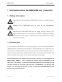
1
SWR-COM
User Manual
Version 1.0
Plug-In Modem for Powerline Communication
with Sunny Boy String Inverters
SWRCOM-11:EE3798
SWR-COM
User Manual
Alteration Review
DocumentNumber
SWRCOM
-11:EE3798
1
)
Version
and Alteration
1
Review )
1.0
A
Comments
Author
New Edition
Salisbury
A: Alterations due to mistakes and errors in previous documents or improvement
of the documentation
B: Alterations maintaining full or upward compatibility
C: Alterations limiting or excluding compatibility
Release
SWRCOM-11:EE
Name
Date
N. Kullik
10.9.1998
-2-
Signature
SMA Regelsysteme GmbH
SWR-COM
User Manual
Explanation of Symbols used in this Document
To enable optimal usage of this manual and safe operation of the device during installation, operation and maintenance routines, please note the following description
of symbols:
This indicates a feature that is important either for optimal and comfortable usage or optimal operation of the system.
Example: „Useful C routines for this purpose are on the support disk.“
This indicates a fact or feature very important for the safety of the user
and / or can cause a serious hardware defect if not appropriately applied.
Example: „Disconnect the mains plug before opening the case!“
This indicates an example.
SWRCOM-11:EE
-3-
SMA Regelsysteme GmbH
SWR-COM
User Manual
Content
1 Information about the SWR-COM and „Powerline“.................................................. 5
1.1 Safety Information ............................................................................................ 5
1.2 Introduction....................................................................................................... 5
1.3 What is Powerline Communication? ................................................................. 6
2 Establishing a Powerline Communication................................................................ 7
2.1 System Requirements ...................................................................................... 7
2.2 What connection to the grid is „suitable“? ........................................................ 7
2.3 Installing the SWR-COM................................................................................... 8
3 Trouble Shooting ................................................................................................... 10
3.1 How to identify the interference source .......................................................... 10
3.1.1 Strong Signal Damping ........................................................................... 11
3.1.2 Phase coupling........................................................................................ 12
3.1.3 Interference signals on the mains ........................................................... 13
3.1.4 Parallel Powerline Communication.......................................................... 14
4 Warrantee Regulations and Liability ...................................................................... 17
5 Technical data ....................................................................................................... 19
SWRCOM-11:EE
-4-
SMA Regelsysteme GmbH
SWR-COM
User Manual
1 Information about the SWR-COM and „Powerline“
1.1 Safety Information
Opening the Powerline Modem SWR-COM is limited to qualified personnel.
Repairs of the SWR-COM must be done by the manufacturer.
Disconnection of the SWR-COM from the supply voltage is done by pulling the SWR-COM out of the socket. It is therefore necessary to always
have access to the socket in order to be able to disconnect the device
whenever necessary.
1.2 Introduction
The transmission link between the Sunny Boy String inverters and the SWR-COM is
established with „Powerline Communication“. This transmission is a simple and reasonable way to transmit data over the mains connection without separate data cables. The Sunny Boy String inverters collect data concerning their operation and
transmit this data to a central unit for further evaluation and storage.
As mentioned above, the Powerline Communication normally is a very simple way to
transmit data, chapter 1. and 2. describe the function and the installation of the
SWR-COM. The chapter 3 covers the different disturbances and interferences that
can (but normally do not) occur with this kind of transmission. You will see that
chapter 3 is very long, but this only in order to cover all possible disturbances and
the according countermeasures.
SWRCOM-11:EE
-5-
SMA Regelsysteme GmbH
SWR-COM
User Manual
1.3 What is Powerline Communication?
Powerline Communication is a data transmission mode where the data is sent over
the normal mains connection. This so called mains connection supplies all electric
devices in the electricity distribution with 230 V / 50 Hz. The data from the Sunny Boy
inverters is sent over the same wire with a carrier frequency of 132,45kHz.
Fig. 1.1: Example for Standard Powerline Communication
With Sunny Data running, the PC collects all available data coming from the Sunny
Boy String Inverters and evaluates and visualizes this data according to your specific
configuration. Setting up and the using Sunny Data is another topic which is described in the Sunny Data manual. The latest version of Sunny Data and the according manual can be downloaded from our Internet site at WWW.SMA.DE.
SWRCOM-11:EE
-6-
SMA Regelsysteme GmbH
SWR-COM
User Manual
2 Establishing a Powerline Communication
In the following a brief description of the installation of the SWR-COM Powerline modem. If you encounter any trouble establishing a connection to the Sunny Boy String
inverters please have a look at chapter 3.
2.1 System Requirements
For the PV-plant monitoring with a SWR-COM and Powerline communication the
following requirements must be fulfilled:
• 1 or more Sunny Boy String Inverters with integrated Powerline modem
(Type SWRxxxx-NE:100, which have to be active in order to be detected by
Sunny Data, so run the installation during daytime)
• a PC (486 or higher, min. 4 MB RAM) with 1 free COM port and Windows 3.x or
Win95
• a Powerline modem (SWR-COM) for connecting this PC to the grid
• the PV-plant monitoring and visualization software Sunny Data
• a suitable connection to the grid for the SWR-COM (see chap. 2.2 and chap. 3)
2.2 What connection to the grid is „suitable“?
The quality of a connection to the grid and the according Sunny Boy String inverters
is essential for the effective data transmission to and from the Sunny Boy inverters.
Beside the fact that transmission in the most cases can be established over very
long distances (150 m and more) and over several phases, we recommend to stick
to the following rules:
SWRCOM-11:EE
-7-
SMA Regelsysteme GmbH
SWR-COM
User Manual
• connect the Sunny Boy Inverters and the SWR-COM to the same phase
(if this is absolutely not possible a phase coupler must most likely be installed, see
chap. 3.)
• keep the transmission line as short as possible.
• make sure that there are as few as possible (best none at all) disturbing electric
devices in your grid. These can be neon tube lamps, some microwave ovens and
sometimes large electric motors or similar.
• avoid the parallel usage of other devices that use the electricity grid for their
transmission such as Babyphone or Interphone devices.
If you stick to (most of) the above given rules there should normally be no problem
for the Powerline Communication - if there are problems with the data transmission
and the detection of the Sunny Boy Inverters see chap. 3 „Troubleshooting“.
2.3 Installing the SWR-COM
The installation of the SWR-COM is done in two steps: First the installation of the
SWR-COM Powerline modem to the grid and the PC, second the installation of
Sunny Data, the detection of the according Sunny Boy inverters and the configuration according to your specific requirements.
For the Sunny Data installation and its usage please refer to the „Sunny Data User
Manual“ - for connecting the SWR-COM do the following:
• write down the serial numbers of the Sunny Boy inverters you want to monitor
• plug the SWR-COM in the socket
• connect the cable from the SWR-COM to a free serial port of the PC (and write
down the port COM1 or COM2 if you can’t remember)
SWRCOM-11:EE
-8-
SMA Regelsysteme GmbH
SWR-COM
User Manual
• run Sunny Data and start monitoring your PV-plant (see the „Sunny Data User
Manual“)
If you encounter any problems during the device detection with Sunny Data see
chap. 3 „Trouble Shooting“.
SWRCOM-11:EE
-9-
SMA Regelsysteme GmbH
SWR-COM
User Manual
3 Trouble Shooting
If the communication between the SWR-COM and the Sunny Boy inverters is not
satisfactory or cannot be established at all, it is necessary to find the reason for this
disturbance for the subsequent appliance of appropriate countermeasures.
Disturbances of the Powerline communication can result from the following:
−
Signal damping
other electric devices
long transmission line
unsuitable electric cabling
−
Insufficient phase coupling
Sunny Boy inverters and SWR-COM are connected to different phases or
missing phase coupler
−
External disturbances
Babyphone usage or similar in the neighborhood
−
Internal disturbances
Internal Babyphone or Intercom usage or similar
These may (but not must) effect the Powerline transmission. In some cases a perfect
data transmission can be established with cable lengths over 150 m and over several phases and sometimes the data transmission will possibly even not work under
apparently perfect conditions. SMA can therefore not guarantee a satisfactory Powerline transmission. How to detect and how to get rid of disturbing factors is described in the following.
3.1 How to identify the interference source
In order to launch appropriate countermeasures it is essential to clearly identify the
interference source. There is a guideline for this identification in the following:
SWRCOM-11:EE
- 10 -
SMA Regelsysteme GmbH
SWR-COM
User Manual
• Starting point for the interference identification is an operating communication.
Connect the SWR-COM with the PC running Sunny Data as close as possible to
the Sunny Boy inverters.
• Disconnect all devices that could disturb the communication. These devices can
be neon tube lamps, washing machines, electric stoves, TVs and so on.
• Set Sunny Data to minimal request cycle (see „Sunny Data user manual“ chap.
3.4 for this). This is done in order to be able to examine the transmission as close
as possible.
• Connect the SWR-COM to different sockets that are each further away from the
Sunny Boy inverters. Observe the transmission - if the transmission starts to break
down after a total cable length of about 30 m the communication most likely is
disturbed
by
external
devices
beyond
the
household
distribution.
(Countermeasure: block filter in front of the house distribution).
• Now re-connect the devices you disconnected from the grid one after the other
and observe the communication. This way you can easily identify the disturbing
device. Once identified, remove the device, connect the device to another phase
or equip your electricity circuit with a block filter.
3.1.1 Strong Signal Damping
Signal damping is the most frequent reason for disturbances of the Powerline communication. The cause for this may be a too long wiring between the inverter and the
Power-Line-Modem, but most times certain electrical devices which are connected to
this line are the reason. Devices with a high input capacity are able to massively
damp the carrier signal independent from the fact if these devices are switched on or
off. Examples for this are washing machines, dryers, electric ranges, microwave ovens, PCs, fluorescent lamps, etc.
SWRCOM-11:EE
- 11 -
SMA Regelsysteme GmbH
SWR-COM
User Manual
Countermeasures against damped signals
(1)
reconnect the disturbing electric device(s) to another phase
(2)
install a special filter in the supply cable of the disturbing electrical devices
(3)
install a separate electricity cable from the inverter(s) to the Powerline modem
Fig. 2.1: Countermeasures against strong signal damping
3.1.2 Phase coupling
If you want the Powerline communication to run over several phases a major signal
damping is the result. A phase coupler can then be necessary.
If the transmission runs over several different phases a phase coupler
may be necessary. Sometimes although the phases are already coupled
by other electric devices in the circuit such as three phase electric motors.
SWRCOM-11:EE
- 12 -
SMA Regelsysteme GmbH
SWR-COM
User Manual
Countermeasure for Powerline transmission over different phases
•
Install a phase coupler
A phase coupler can result in the following disadvantages:
The detour over the phase coupler leads to very long transmission distances and a signal damping.
The high-frequency coupling of the three phases can reinforce the influence of disturbing devices connected to the other phases.
Abb. 2.2: Installation of a phase coupler for transmission over several phases
3.1.3 Interference signals on the mains
The data transmission uses a carrier frequency of 132.45 kHz. If other consumers
emit signals in this frequency range to the mains, the transmission can disturbed
when these exceed a certain level. These interference signals can be internally
emitted by electrical devices within your own household (insufficiently filtered devices
like unshielded transformers), but they can also result from devices outside of the
household distribution (e.g. high power machines in the neighborhood).
SWRCOM-11:EE
- 13 -
SMA Regelsysteme GmbH
SWR-COM
User Manual
Countermeasures for internal and external interference
• Remove the disturbing device if possible
• Isolate the disturbing device by either connecting the device to another phase or
• Install a block filter (1). This block filter disconnects the part of the houses electric
distribution used for the Powerline data transmission, from the section of the of the
mains with the interfering devices. The effect of the blocking filter can be reinforced by the installation of an active damping module on the side of interference
(before the block filter), which is active in the carrier frequency band (2).
Fig. 2.3: Powerline communication in case of strong interference
3.1.4 Parallel Powerline Communication
It can be a problem when other devices use the electricity supply for communication
as well as the SWR-COM. The situation is similar to devices emitting interfering signals, only the strict disconnection of the transmission lines can help in these cases.
But in contrary to the method described in the previous chapter the damping of the
disturbing signal does not help here. After all both communication systems have to
operate parallel. At least one of the used systems should therefore be restricted to
SWRCOM-11:EE
- 14 -
SMA Regelsysteme GmbH
SWR-COM
User Manual
the utilization of one phase. Then this part of electrical installation can be equipped
with a block filter, which makes sure that neither high-frequent „alien“ signals get in
nor that the own carrier signals are able to leave this part of electrical installation.
Countermeasures for parallel Powerline communication
• In case of a strong coupling such a restriction of the transmission link and the utilization of a block filter can be necessary for each of the used communication systems (1).
• An improvement can be achieved with damping modules, which extend the effect
of the blocking filter by damping high-frequency signals selectively (2). Such a
damping module may exclusively be installed in that part of the electrical installation where all transmission signals are not needed.
Fig. 2.4: Powerline Communication with other devices
SWRCOM-11:EE
- 15 -
SMA Regelsysteme GmbH
SWR-COM
User Manual
Advice:
All additional components (carrier-current line trap, phase coupler, filter, damping
module) are standard electric equipment and can be purchased from the local electrician supply or from SMA. The devices are installed in the house distribution while
the installation must be done by qualified personnel.
SWRCOM-11:EE
- 16 -
SMA Regelsysteme GmbH
SWR-COM
User Manual
4 Warrantee Regulations and Liability
You have purchased a product which was thoroughly checked before delivering. If
your device should be defective or show a malfunction during the guaranty period in
spite of this, please contact your distributor or installer.
Warranty
The warranty period is 12 months from the date of purchasing the device by the end
user. It ends at the latest 18 months after the delivery date at SMA, and includes all
defects caused by material or manufacturing faults.
The guaranty period for warranty repairs or compensation deliveries ends 6 months
after delivery, but runs at least until the expiration of the original guaranty period for
the delivered item.
Evidence
SMA will only render warranty services, if the objected device is sent back to SMA
together with a copy of the account the distributor has made out to the consumer.
The type plate at the device must be readable completely. In case of nonfulfilment
SMA reserves the right to refuse guaranty services.
Conditions
The device will be repaired after the choice of SMA in its works without invoice of
material and work, or a replacement resp. compensation device will be delivered.
The objected device is to be sent back to SMA without charges in the original packing, or in a transport packing of equal quality.
The customer has to grant SMA the necessary time and opportunity to repair the
defects.
SWRCOM-11:EE
- 17 -
SMA Regelsysteme GmbH
SWR-COM
User Manual
Exclusion of Liability
Excluded are any guaranty claims and liabilities for direct or consequential damages
due to
−
shipping damages,
−
faulty installation or putting into operation,
−
engagements, alterations, or repairing attempts,
−
inappropriate use or operation,
−
insufficient air supply to the device,
−
non-observance of relevant safety regulations (VDE etc.),
−
or force majeure (lightning, overvoltage, storm, fire).
Caution! We cannot guarantee the proper function of the data transmission via
mains lead (power line modem) in case it is carried out in electrical grids with high
harmonic distortion resp. high-frequency line distortions like e.g. industrial power
supply grids, or in the neighborhood of irregular consumers (unshielded motors,
switching power supplies, converters etc.) Furthermore, the simultaneous operation
of babyphones may lead to short-time data transmission disturbances or interruptions. In case of disturbed data transmission via mains lead, we offer alternatively a
communication via separate data line as option (RS232 or RS485) (see Technical
description Sunny Boy.
We reserve the right to make alterations serving for the improvement of the device.
Further or other claims for direct or indirect damages, especially including claims for
damages from positive contract violation, are excluded insofar as not otherwise
compelling stated by law.
SWRCOM-11:EE
- 18 -
SMA Regelsysteme GmbH
SWR-COM
User Manual
5 Technical data
mains voltage:
230 V + 10 % / - 15 %
power consumption:
approx. 5 W
carrier frequency:
132, 45 kHz
transmission protocol:
according to DIN EN 50065 part 1 (VDE 0808 part 1)
ambient temperature:
0 ... 40 °C
size (mm):
126 x 75 x 53 (without plug and cable)
weight:
approx. 550 g
degree of protection:
IP 20
fuse:
fine-wire fuse, 250 V / 0,315 A slow blow
Connections:
- integrated mains plug
for direct insertion into a-socket
- connection cable
2 m with D-SUB connector (socket, 9-pin)
for direct insertion into COM1- or COM2 connector
of a PC (RS232)
Note:
The parallel operation of the Powerline modem together with other devices, which use the network for data transmission as well but do not
comply with the standardized transmission protocol, is normally not
possible.
SWRCOM-11:EE
- 19 -
SMA Regelsysteme GmbH
SWR-COM
User Manual
Accessories (optional):
- interface adapter
D-SUB plug adapter 9-pin to 25-pin
For installation in the house distribution:
- phase coupler
Busch-Jaeger Elektro GmbH, Typ 2291 Kb-101
- carrier current line trap
Busch-Jaeger Elektro GmbH, Typ 2293-63 kB
- device filter
Busch-Jaeger Elektro GmbH, Typ 2294/16 kB
- damping module
Busch-Jaeger Elektro GmbH, Typ 2260
SWRCOM-11:EE
- 20 -
SMA Regelsysteme GmbH