1
batteries are listed in the Specifications. When operating from aircraft power
the backlight consumption is of no concern since it is so small compared to
battery capacity. Even though lifetime from a 9V battery is limited it should be
seriously considered, as there is no worry about damaging the instrument from
a runaway voltage regulator, which can happen with a 14 or 28V system. The
tach can be switched from backlight to no backlight (or vice versa) without
restarting if the POWER switch is operated very quickly. Flip the switch in one
continuous quick motion and operation will not be interrupted.
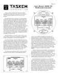
When first turned on the tach illuminates all of the LCD segments for a few
seconds. This is to test them and make sure they are all present as shown in the
following figure. At this point the LOBAT legend does not mean that the
battery is weak but simply that the LCD legend itself is working. When the
battery is low (less than 6.9V) the LOBAT legend will flash on and off
continuously. At this point there is
ample power in a 9V alkaline
battery to operate the tach for
several more hours without
backlight but the battery should be
replaced on landing.
After the LCD test is complete the tach will then do a visual test of all LEDs
by lighting each one in sequence. It will do this twice starting with the yellow,
progressing through each of the green, to the red and then sequentially back to
the yellow. During this check you should verify that all LEDs are working.
The red LED represents REDLINE (RL) and indicates that the engine RPM is
exceeding a preset limit. The limit is usually provided by the engine
manufacturer and is the speed beyond which engine damage is likely to occur.
The desired RL value can easily be set and the procedure will be explained
shortly. When the RL is exceeded the red LED will flash on and off as a
warning. The yellow LED represents YELLOWLINE (YL) and lights to warn
when RPM has fallen below a preset value. This can be used in one of two
ways. For carbureted engines this is usually set to the PRM where heat is
required to prevent carburetor icing. For fuel injected engines it can be set to a
low RPM where rough running and an engine stall are imminent. The
remaining ten green LEDs are then divided into equal spans between the YL
and RL limits. Thus, if YL were set to 700 and RL to 2700 (typical values for a
small carbureted aircraft engine) the ten green LEDs would be divided equally
into 2000/10 or 200 RPM steps. The first green would indicate 700-900 RPM,
the second 900-1100, the third 1100 to 1300, etc.
There is one other configuration feature that rarely needs to be addressed.
Referring to the circuit board layout diagram you will see a large capacitor
identified as a noise filter. This is located very close to the 10-pin connector.
This capacitor eliminates high frequency noise from getting into the input
circuitry. This is very effective and needed for almost all applications with one
exception. This is the situation where the tach signal is obtained from a
connection to the mechanical “points” of an old style ignition system. In this
case the ignition system already has a capacitor installed (usually inside the
distributor) and its value is critical to achieving full spark potential. The
additional capacitor in the tachometer will upset the normal operation of the
ignition system and the resulting spark voltage will be reduced. In this situation
the capacitor internal to the tach must be removed and the capacitor inside the
distributor will provide the needed noise rejection. There are two simple ways
to do this. One is to heat one of the capacitor solder connections with a
soldering iron and lift that end of the capacitor out of the circuit board. The
capacitor should then be rotated slightly so that there is no chance that the wire
lead can come in contact with the eye in the circuit board. The other method is
to cut one of the copper traces on the underside of the circuit board. If you look
carefully at the underside of the circuit board directly opposite the capacitor
you will see the word “CUT” and an arrow. This points to a small wire trace
that is silver in color as opposed to all others that are covered with a protective
green coating. Cut the indicated trace and the capacitor will be electrically
removed from the circuit. It is not necessary to cut deep into the circuit board.
All that is needed is to cut deep enough and wide enough to see a definite gap
in the wire trace. A Dremmel tool with a small burr does the job very neatly.
Repeated scoring with a pocketknife will also work, but it is difficult to do
without slipping and damaging other wire traces. As before, the Engine
Datasheet identifies when this is required.
Every effort has been put into providing you with a highly accurate and
equally reliable instrument. All components are rated far in excess of what they
will normally be subjected to in terms of temperature and power. In addition,
an extensive burn-in weeds out any early component defects, and our 1 year
warranty against defects in materials and workmanship is one more assurance
of satisfaction. As with any electronic device, care should be taken not to leave
it exposed to the elements. It is not waterproof and may sustain permanent
damage if exposed to rain or salt air. The instrument should never be
transported or left outside uncovered, particularly overnight. Please be sure to
fill out and return the Warranty Registration card. Beyond the warranty period,
quick service can always be obtained direct from our factory at reasonable cost.
After the LED test is complete the tach will then proceed to alternately show
the LAST and TOTAL (Hobbs) engine times. It continues alternating between
these two as long as the engine is not started. The LAST time is displayed in
-2-
Rev. 2010 Feb 25
-7-