1
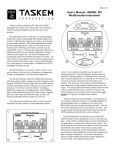
Jumpers 7, 8, 9 & 10 select the number of pulses (or cycles) per revolution
(PPR) that the engine’s electrical signal produces. For instance, if the signal
were derived from a magnetic sensor and single magnet placed on the flywheel,
this would produce 1 PPR. There are many options including 0.5 PPR (one
pulse for every other revolution). At first glance this might seem absurd but it
applies to 4-stroke engines or if the signal is derived from the camshaft instead
of the crankshaft. The table below gives the PPR jumper plug settings. Note
that jumpers are only “read” by the computer when the power switch is first
turned on, so any changes while power is on will have no effect.
Jumper J11 selects AVERAGING. All engines, particularly small 2-strokes,
exhibit a certain amount of short-term variation in their speed. The tach
actually takes a new RPM reading every 0.6 seconds, but if these readings were
displayed “as is” we would see these variations as constant changes in the
lesser RPM digits. This is also amplified by the fact that the resolution of the
tach is only 10 RPM, much finer than you can see on an analog tach. If the J11
jumper is removed, displayed RPM is averaged over the last 4 successive
readings. With it in place averaging is over the last 8 readings. Longer
averaging extends the tach response time. For instance, if you change the
engine RPM abruptly, it will take longer for the tach to respond.
Jumpers J12 and J13 must always be installed or removed as a pair. Their
function is to enable or disable a full-wave rectifier that is incorporated in the
input circuitry. This is a device that basically changes AC to DC, or in this
application, positive and negative pulses to all positive. The rectifier is rarely
used but is needed for direct connection to the "P lead” of certain magnetos.
With the jumpers in place the rectifier is disabled, as the jumpers bypass it.
Unless specially requested, instruments are shipped with the jumpers in place.
To enable the rectifier, remove the jumpers. Details on when the rectifier is
needed can be found in the Engine Datasheet.
-6-
hours and minutes with a colon separator (03:47) while the TOTAL time is
displayed in hours and tenths of an hour separated by a decimal point (123.4).
In most cases engine time and flight times are almost the same so LAST time
can refer to either. Once the engine is started, times are replaced by RPM and
the LAST time will be cleared and start incrementing from zero. At any time
during flight pressing and holding the MODE button will replace RPM with
LAST time, but this is now understood to be the current flight time since it was
cleared when the engine was started. Releasing the MODE button restores the
digital RPM display.
As mentioned previously once the YL and RL are set, the difference between
them is divided up equally and the green LEDs reflect that uniform span. To
set the thresholds turn the tach on and while the LCD test is in progress, press
and hold the MODE pushbutton. After a few seconds the yellow and adjacent
green LEDs will start flashing and the current YL value will be displayed on
the LCD. Release the MODE button. The YL value is the threshold between
the yellow and green LED, thus the two flashing lights. If the current setting is
O.K. do nothing, as a few seconds of inactivity will advance to the RL. If you
want to change the YL value each press of the MODE button will increment it
in 50 RPM steps to a maximum of 1,500. To decrement the setting press and
hold the MODE button ‘till a negative sign appears then release it. With the
minus sign present each push of the MODE button will decrement the YL. The
YL can be decremented to zero, which basically disables it. In this case the
yellow LED will never light and the green LEDs are divided equally from zero
to RL. If you wish to increment again, press and hold the MODE button ‘till
the minus sign disappears then release it. As before, each press of the MODE
button while the minus sign is not present will increment. Now wait a few
seconds and the tach will advance to the RL value. The red and adjacent green
LEDs will alternately flash and the current setting will be visible on the LCD.
As with the YL setting, each press of the MODE button will either increment or
decrement the value depending on the status of the minus sign. The RL can not
be set any lower than 2,000 and the maximum value is 19,950. Unlike the YL
it can not be disabled. Six seconds of inactivity will exit this function and store
the YL and RL values in permanent memory.
After a flight is completed and the engine is shut off, the tach will revert to
the alternating LAST and TOTAL time displays. These are stored in
permanent memory and will not be lost even if the tach is turned off. These
same LAST and TOTAL times will appear when the tach is again turned on.
As long as the engine is not started, the LAST time will not be cleared and will
remain visible. This is handy if you forgot to make a log entry of your last
flight time as it is still there. Once the engine is started, LAST time is cleared
to zero and a new measurement starts.
-3-