1
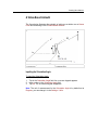
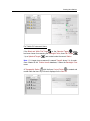
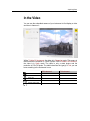
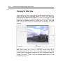
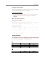
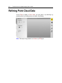
The Deliveries
Modifying a Reference Plane
A Reference Plane is a plane on which points from the acquired data will be
projected. This Reference Plane combined with the Job Resolution (defined
in a Volume (or DTM) job) will be used for a computing a Volume (or Mesh).
Modifying the Reference Plane parameters will update the Delivery data (both
the Positive (Cut) and Negative (Fill) values in Volumes and the number of
computed triangles in DTM).
Setting a Direction
A Reference Plane's direction is given by its Normal. By default, the Normal
direction is parallel to the Z axis of the active coordinate frame (0, 0, 1 as X,
Y, Z coordinates).
To Set a Direction:
1.
2.
3.
4.
Tap in the X field. An on-screen keypad appears.
Input a value in the X field.
Tap Ok. The on-screen keypad disappears.
Repeat the steps from 1 to 3 for Y and Z.
Tip: You can also tap the Tab button to jump from a field to edit to another.
Setting a Position
A Reference Plane's position is given by one point. If the instrument is not
setup; this position corresponds to its center. If the instrument is setup over a
known point; the default Reference Plane's position will be set at the first
station ground point.
To Set a Position:
1.
2.
3.
Tap in the Altitude field*. An on-screen keypad appears.
Input a value in the Altitude field*.
Tap Ok. The on-screen keypad disappears.
Note: (*) The Altitude field is not available in a DTM job.