1
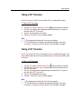
User's Guide
Trimble Access for
Spatial Imaging
Printed on 28 June, 2010
Contents
Legal Notices
Getting Started
System Requirements
Installing Trimble Access Installation Manager
Installing and Updating Trimble Access
Licensing Trimble Access and Components
Using Trimble Access
Starting Trimble Access
Exiting Trimble Access
About Trimble Access
Understanding Trimble Access's Concepts
Having an Overview of a Job Workflow
Browsing Through a Step
Going Back to the Trimble Access Home Page
Setting up a Network Connection
Configuring the TCP/IP Settings for a Wireless Network Connection
Configuring the TPC/IP Settings for a Local Area Connection
Setting up a Wi-Fi Connection to the Trimble GX instrument
Checking the Windows Firewall
Turning Off the Windows Firewall
Connecting to an Instrument
Connecting to a Trimble GX instrument
Updating the Trimble GX instrument's Firmware
9
15
17
18
18
19
21
23
24
25
26
26
27
28
29
31
32
33
34
35
37
39
41
ii
Contents
Connecting to a Trimble CX instrument
Checking the Connection Status
Requesting a Connection to an Instrument
Checking the Wireless Signal Strength
Checking the TPC/IP Settings
The Laser Safety Standards
Choosing a Laser Safety Standard
Viewing the Laser Safety Class
Leveling and Compensating an Instrument
Leveling a Trimble GX instrument
The Instrument is Out of Range
The Instrument is Misleveled
The Instrument is Leveled
Leveling a Trimble CX instrument
Measuring the Tilt
The Instrument is Misleved
The Instrument is Leveled
Activating and Deactivating the Compensator
Activating the Compensator
Deactivating the Compensator
Correcting the Atmospheric Parameters
Inputting a PPM Value
Computing a PPM Value
Keeping the Atmospheric Correction Deactivated
Creating Jobs
A General Scanning Job
Editing Newly Created Project Name
Loading Last Project
Loading Existing Project
A Volume Job
Editing Newly Created Project Name
Loading Last Project
Loading Existing Project
A DTM Job
Editing Newly Created Project Name
Loading Last Project
Loading Existing Project
A Job Resolution
Defining a Job Resolution
Modifying a Job Resolution
43
45
46
47
48
49
49
50
51
53
53
54
55
56
56
57
58
59
59
59
60
60
61
61
63
65
65
66
66
67
68
68
69
70
70
71
71
72
72
72
Contents
Creating New Stations
When the Instrument is Leveled
When the Instrument is Misleveled
Setting up a Station with Known Coordinates or Azimuth
Creating a Station Known Point
Importing a List of Known Points
Selecting a Station Known Point
Setting the Station Parameters
Orientating a Station With
Setting up a Station Using Multiple Point Resection
Creating the First Backsight Known Point
Importing a List of Known Points
Selecting the First Backsight Known Point
Setting the First Backsight Parameters
Measuring the First Backsight Point
Creating the Second Backsight Known Point
Importing a List of Known Points
Selecting the Second Backsight Known Point
Setting the Second Backsight Parameters
Measuring the Second Backsight Point
The Target-Based Registration Report by Stations
Ending the Station Setup Using Multiple Point Resection
Stationing Review in the Project Tree
Setting up a Station Based on Three Backsight Measurements
Defining a New Station Name
Creating the First Backsight Known Point
Importing a List of Known Points
Selecting the First Backsight Known Point
Measuring the First Backsight Point
Creating the Second Backsight Known Point
Importing a List of Known Points
Selecting the Second Backsight Known Point
Measuring the Second Backsight Point
Creating the Third Backsight Known Point
Importing a List of Known Points
Selecting the Third Backsight Known Point
Measuring the Third Backsight Point
The Target-Based Registration Report by Stations
Ending the Station Setup
Stationing Review in the Project Tree
Not Setting up a Station
Defining a New Station Name
Stationing Review in the Project Tree
73
75
76
77
77
78
80
81
83
100
100
101
103
104
104
105
106
107
107
108
109
110
111
114
114
114
115
118
118
119
120
121
121
122
123
124
124
125
125
126
128
128
129
iv
Contents
Adding Foresight Points
Adding New Backsight Points
Setting up a Target-Based Registration Report
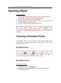
Viewing a Report
Exporting a Report
Choosing a Destination Folder
Defining the Destination File Name
Defining the Destination File Type
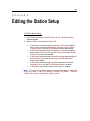
Editing the Station Setup
Changing the Station Height
Changing the Station Known Point
Editing the Station Backsight Points
Changing a Point Height
Changing the Backsight Point
Ignoring the Backsight Point
Applying a Traverse
Applying a Global Adjustment
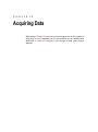
Acquiring Data
In a General Scanning Job
In a Volume Job
In a DTM Job
Acquiring Scans
Defining a Zone of Interest
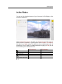
In a New Panorama
In the Video
In a 360° Pre-Scan
In an Existing 3D View
Defining a Frame
Defining a Rectangular Frame
Defining a Polygonal Frame
Editing Vertices
Deleting a Frame
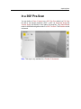
Acquiring Images of Scan Area
Setting Panorama Resolutions
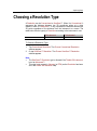
Choosing a Resolution Type
Setting a Conventional Resolution
Setting a SureScan Resolution
Customizing the Scan Options
Defining the Scan Options
130
131
133
135
136
136
137
137
139
141
142
143
144
144
145
146
147
149
151
152
153
154
155
156
161
167
168
169
170
170
171
171
172
172
173
174
177
178
181
Contents
Choosing a Scan Method
Acquiring Full Scans
A TZS Full Scan
A CMF Full Scan
Acquiring Survey Points
Defining a Survey Point Name
Collecting a Survey Point
Adding a New Survey Point
The Survey Point Results
Pausing on Data Acquisition
Interrupting
Resuming
Stopping
Cancelling
The Auto-Calibration in Progress
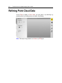
Refining Point Cloud Data
Fencing Data
Filtering Data
Checking the Refinement Results
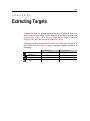
Extracting Targets
The Spherical Target Feature
The Flat Target Feature
The Fast Flat Target Feature
The Black and White Target Feature
Extracting a Target
Auto-Framing a Target
Manual-Framing a Target
Defining Measurement Settings for a Spherical Target
Defining the Number of Iterations
Defining the Sphere Diameter
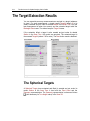
The Target Extraction Results
The Spherical Targets
The Reflective Flat Targets
The Black and White Targets
183
188
188
188
189
190
190
191
191
192
193
193
193
194
194
196
198
200
202
203
205
206
207
208
209
210
211
212
212
213
214
214
215
215
vi
Contents
Rechecking Targets
217
Remeasuring Targets
Interrupting the Recheck Process
Resuming the Recheck Process
219
220
220
Measuring an Instrument Height
221
Measuring the Trimble GX instrument Height
Measuring the Top Notch Height
Measuring the Bottom Notch Height
Measuring the Trimble CX instrument Height
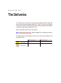
The Deliveries
A Volume Delivery
Post Processing a Volume
Exporting a Volume
Editing Parameters in Volume(s)
A Mesh Delivery
Post Processing a Mesh
Exporting a Mesh
Export Parameters
Editing Parameters in Mesh(es)
Modifying a Volume Job Resolution
Modifying a Mesh Job Resolution
Modifying a Reference Plane
Setting a Direction
Setting a Position
Measuring a Reference Plane
Projects
Performing Basic Operations on Projects
Managing Projects
Creating a New Project
Importing as a Project
Import Parameters
Viewing a Project as Data Tree
The Project Tree
Viewing a Tree
Going Down in a Parent Node
Going Up to a Parent Node
Sorting-out Objects
223
224
224
225
227
229
230
233
235
236
237
241
244
248
249
250
251
251
251
252
255
257
258
263
264
266
268
269
273
273
273
274
Contents
Renaming Objects
Object Properties
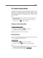
Viewing a Project as 3D Data
About the View 3D
Viewing Objects
Hiding all Objects
Rotating an Object
Panning an Object
Zooming In or Out
Viewing all
Zooming on Selection
Changing the Rotation Center
The Station-Based Mode
The Examiner Mode
The Rendering Options
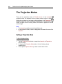
The Projection Modes
The Standard Views
The Instrument Tools
The On-Site Video Calibration Tool
Prerequisites
Starting the Tool
Calibrating the Video
Video Calibration Errors
The Auto-Test Tool
Auto-Testing the Trimble GX instrument
Saving the Auto-Test Result as a Report
The Leveling Tool
Opening the Leveling Tool
Leveling a Trimble GX instrument
Leveling a Trimble CX instrument
Activating and Deactivating the Compensator
Correcting the Atmospheric Parameters
The Files Folder
Opening the Files Folder
Copying Files into the Files Folder
Settings
Defining a Setting
General Settings
Changing the Coordinate System
Changing the Temporary Folder
274
274
276
276
277
278
278
279
279
279
280
280
281
282
283
286
287
289
291
291
292
293
294
295
295
296
297
297
299
302
305
306
309
311
312
313
315
316
316
316
viii
Contents
Restoring the Default Folder
Cleaning the Current Folder
Units Settings
Defining the Decimal Places
Displaying a Value With Unit Tag
Defining a Unit of Measurement
Network Settings
Choosing an Instrument to be Connected to
317
317
318
318
318
319
320
320
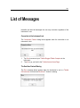
List of Messages
321
Glossary of Terms
325
Index
327
9
Legal Notices
AGREEMENT ("AGREEMENT") IS A LEGAL AGREEMENT BETWEEN YOU
AND TRIMBLE NAVIGATION LIMITED and applies to the computer software
provided as a stand-alone computer software product, or provided with the
Trimble product purchased by you (whether built into hardware circuitry as
firmware, embedded in flash memory or a PCMCIA card, or stored on
magnetic or other media), and includes any accompanying written materials,
such as a user's guide or product manual, as well as any "online" or
electronic documentation ("Software"). This Agreement will also apply to any
Software error corrections, updates and upgrades subsequently furnished by
Trimble, unless such are accompanied by different license terms and
conditions which will govern their use. BY CLICKING "YES" OR "I ACCEPT"
IN THE ACCEPTANCE BOX, OR BY INSTALLING, COPYING OR
OTHERWISE USING THE SOFTWARE, YOU AGREE TO BE BOUND BY
THE TERMS OF THIS AGREEMENT.IF YOU DO NOT AGREE TO THE
TERMS OF THIS AGREEMENT, PROMPTLY RETURN THE UNUSED
SOFTWARE AND ANY ACCOMPANYING TRIMBLE PRODUCT TO THE
PLACE FROM WHICH YOU OBTAINED THEM FOR A REFUND. This
Software is protected by copyright laws and international copyright treaties,
as well as other intellectual property laws and treaties. The Software is
licensed, not sold.
1 SOFTWARE PRODUCT LICENSE
1.1
License Grant. Subject to the terms and conditions of this
Agreement and your pre-payment of the applicable license fee(s), Trimble
grants you a non-exclusive, right to use one copy of the Software in machinereadable form on any computer hardware and operating system for which it
was intended, but solely for your internal business needs in connection with
your use of Trimble products. You may authorize the personnel associated
with your business to use the Software, but only one person at one time, on
one computer at one time. You may also store or install a copy of the
Software on a storage device, such as a network server, used only to install
or run the Software on your other computers over an internal network; but in
such case you must acquire and dedicate a seat license for each separate
computer on which the Software is installed or run from the storage device. A
seat license for the Software may not be shared or used concurrently on
different computers/devices. Use of the Software is limited to the total
number of installation copies and seat licenses purchased by you.
10
Trimble Access for Spatial Imaging User's Guide
1.2
Other Rights and Limitations. (1) You may not copy, modify, make
derivative works of, rent, lease, sell, distribute or transfer the Software, in
whole or in part, except as otherwise expressly authorized under this
Agreement, and you agree to use all commercially reasonable efforts to
prevent its unauthorized use and disclosure. (2) The Software contains
valuable trade secrets proprietary to Trimble and its suppliers. To the extent
permitted by relevant law, you shall not, nor allow any third party to copy,
decompile, disassemble or otherwise reverse engineer the Software, or
attempt to do so, provided, however, that to the extent any applicable
mandatory laws give you the right to perform any of the aforementioned
activities without Trimble's consent in order to gain certain information about
the Software for purposes specified in the respective statutes (e.g.,
interoperability), you hereby agree that, before exercising any such rights,
you shall first request such information from Trimble in writing detailing the
purpose for which you need the information. Only if and after Trimble, at its
sole discretion, partly or completely denies your request, may you exercise
such statutory rights. (3) The Software is licensed as a single product. You
may not separate its component parts for use on more than one computer
except as specifically authorized in this Agreement. (4) You may not rent,
lease or lend the Software unless you are a reseller of Trimble products
under separate written agreement with Trimble and authorized by Trimble to
do so. (5) You may permanently transfer all of your rights under this
Agreement, provided you retain no copies, you transfer all of the Software
(including all component parts, the media and printed materials, any
upgrades, and this Agreement) and the recipient agrees to the terms of this
Agreement. If the Software portion is an upgrade, any transfer must include
all prior versions of the Software. (6) You may not use the Software for
performance, benchmark or comparison testing or analysis, or disclose to any
third party or release any results thereof (all of which information shall be
considered Trimble confidential information) without Trimble's prior written
consent. (7) You may not directly or indirectly export or re-export, or
knowingly permit the export or re-export of the Software (or portions thereof)
to any country, or to any person or entity subject to export restrictions of the
United States, the countries of the European Union or other countries in
contravention of such laws and without first obtaining appropriate license. (8)
You agree to cooperate with Trimble to track the number of server computers,
computers and other devices with access to the Software at your site(s) to
ensure compliance with the license grant and installation restrictions in this
Agreement. In the event the compliance check reveals that the number of
installations at your site exceeds the actual number of licenses obtained by
you, you agree to promptly reimburse Trimble three (3) times the then current
applicable list price for the extra licenses that are required to be compliant,
but that were not obtained, as liquidated damages and as a reasonable
penalty.
Legal Notices
1.3
Termination. You may terminate this Agreement by ceasing all
use of the Software and destroying or returning all copies. Without prejudice
as to any other rights, Trimble may terminate this Agreement without notice if
you fail to comply with the terms and conditions of this Agreement. In such
event, you must cease its use destroy all copies of the Software and of its
component parts.
1.4
Copyright. All title and copyrights in and to the Software (including
but not limited to any images, photographs, animations, video, audio, music,
and text incorporated into the Software), the accompanying printed materials,
and any copies of the Software are owned by Trimble and its suppliers. You
shall not remove, cover or alter any of Trimble's patent, copyright or
trademark notices placed upon, embedded in or displayed by the Software or
on its packaging and related materials. You may, however, either (1) make
one copy of the Software solely for backup or archival purposes, or (2) install
the Software on a single computer provided you keep the original solely for
backup or archival purposes. You may not copy the accompanying printed
materials.
1.5
U.S. Government Restricted Rights. The Software is provided with
"RESTRICTED RIGHTS." Use, duplication, or disclosure by the United
States Government is subject to restrictions as set forth in this Agreement,
and as provided in DFARS 227.7202-1(a) and 227.7202-3(a) (1995), DFARS
252.227-7013(c)(1)(ii) (OCT 1988), FAR 12.212(a) (1995), FAR 52.227-19, or
FAR 52.227-14(ALT III), as applicable.
2 LIMITED WARRANTY.
2.1
Limited Warranty. Trimble warrants that the Software will perform
substantially in accordance with the accompanying written materials (i.e.,
applicable user's guide or product manual) for a period of one (1) year from
the date of purchase. This limited warranty gives you specific legal rights; you
may have others, which vary from state/jurisdiction to state/jurisdiction. The
above limited warranty does not apply to error corrections, updates or
upgrades of the Software after expiration of the limited warranty period, which
are provided "AS IS" and without warranty unless otherwise specified in
writing by Trimble. Because the Software is inherently complex and may not
be completely free of nonconformities, defects or errors, you are advised to
verify your work. Trimble does not warrant that the Software will operate
error free or uninterrupted, will meet your needs or expectations, or that all
nonconformities can or will be corrected.
12
Trimble Access for Spatial Imaging User's Guide
2.2
Customer Remedies. Trimble's and its suppliers' entire liability,
and your sole remedy, with respect to the Software shall be either, at
Trimble's option, (a) repair or replacement of the Software, or (b) return of the
license fee paid for any Software that does not meet Trimble's limited
warranty. The foregoing limited warranty is void if failure of the Software has
resulted from (1) accident, misuse, abuse, or misapplication; (2) alteration or
modification of the Software without Trimble's authorization; (3) interaction
with software or hardware not supplied or supported by Trimble; (4) your
improper, inadequate or unauthorized installation, maintenance or storage; or
(f) if you violate the terms of this Agreement. Any replacement Software will
be warranted for the remainder of the original warranty period or thirty (30)
days, whichever is longer.
2.3
NO OTHER WARRANTIES. TO THE MAXIMUM EXTENT
PERMITTED BY APPLICABLE LAW, TRIMBLE AND ITS SUPPLIERS
DISCLAIM ALL OTHER WARRANTIES, TERMS, AND CONDITIONS,
EITHER EXPRESS OR IMPLIED, BY STATUTE, COMMON LAW OR
OTHERWISE, INCLUDING BUT NOT LIMITED TO, IMPLIED WARRANTIES,
TERMS, AND CONDITIONS OF MERCHANTABILITY AND FITNESS FOR A
PARTICULAR PURPOSE, TITLE, AND NONINFRINGEMENT WITH
REGARD TO THE SOFTWARE, ITS SATISFACTORY QUALITY, AND THE
PROVISION OF OR FAILURE TO PROVIDE SUPPORT SERVICES. TO
THE EXTENT ALLOWED BY APPLICABLE LAW, IMPLIED WARRANTIES,
TERMS AND CONDITIONS ON THE SOFTWARE ARE LIMITED TO ONE
(1) YEAR. Y0U MAY HAVE OTHER LEGAL RIGHTS WHICH VARY FROM
STATE/JURISDICTION TO STATE/JURISDICTION.
2.4
LIMITATION OF LIABILITY. TO THE MAXIMUM EXTENT
PERMITTED BY APPLICABLE LAW, IN NO EVENT SHALL TRIMBLE OR
ITS SUPPLIERS BE LIABLE FOR ANY SPECIAL, INCIDENTAL, INDIRECT
OR CONSEQUENTIAL OR PUNITIVE DAMAGES, HOWEVER CAUSED
AND REGARDLESS OF THE THEORY OF LIABILITY (INCLUDING,
WITHOUT LIMITATION, DAMAGES FOR LOSS OF BUSINESS PROFITS,
BUSINESS INTERRUPTION, LOSS OF BUSINESS INFORMATION, OR
ANY OTHER PECUNIARY LOSS), ARISING OUT OF THE USE OR
INABILITY TO USE THE SOFTWARE, OR THE PROVISION OF OR
FAILURE TO PROVIDE SUPPORT SERVICES, EVEN IF TRIMBLE HAS
BEEN ADVISED OF THE POSSIBILITY OF SUCH DAMAGES, AND
NOTWITHSTANDING ANY FAILURE OF ESSENTIAL PURPOSE OF ANY
EXCLUSIVE REMEDY PROVIDED IN THIS AGREEMENT.IN NO EVENT
SHALL TRIMBLE'S TOTAL LIABILITY IN CONNECTION WITH THIS
AGREEMENT OR THE SOFTWARE, WHETHER BASED ON CONTRACT,
WARRANTY, TORT (INCLUDING NEGLIGENCE), STRICT LIABILITY OR
OTHERWISE, EXCEED THE ACTUAL AMOUNT PAID TO TRIMBLE FOR
USE OF THE SOFTWARE GIVING RISE TO THE CLAIM. BECAUSE SOME
STATES AND JURISDICTIONS DO NOT ALLOW THE EXCLUSION OR
LIMITATION OF LIABILITY FOR CONSEQUENTIAL OR INCIDENTAL
DAMAGES, THE ABOVE LIMITATION MAY NOT APPLY TO YOU.
Legal Notices
2.5
PLEASE NOTE: THE ABOVE TRIMBLE LIMITED WARRANTY
PROVISIONS MAY NOT APPLY TO SOFTWARE PRODUCTS
PURCHASED IN THOSE JURISDICTIONS (SUCH AS COUNTRIES OF THE
EUROPEAN
ECONOMIC COMMUNITY)
IN WHICH
PRODUCT
WARRANTIES ARE OBTAINED FROM THE LOCAL DISTRIBUTOR. IN
SUCH CASE, PLEASE CONTACT YOUR TRIMBLE DEALER FOR
APPLICABLE WARRANTY INFORMATION.
3 GENERAL.
3.1
This Agreement shall be governed by the laws of the State of
California and applicable United States Federal law without reference to
"conflict of laws" principles or provisions. The United Nations Convention on
Contracts for the International Sale of Goods will not apply to this Agreement.
Jurisdiction and venue of any dispute or court action arising from or related to
this Agreement or the Software shall lie exclusively in or be transferred to the
courts the County of Santa Clara, California, and/or the United States District
Court for the Northern District of California. You hereby consent and agree
not to contest, such jurisdiction, venue and governing law.
3.2
Section 3.1 notwithstanding, if you acquired this product in
Canada, this Agreement is governed by the laws of the Province of Ontario,
Canada. In such case each of the parties to this Agreement irrevocably
attorns to the jurisdiction of the courts of the Province of Ontario and further
agrees to commence any litigation that may arise under this Agreement in the
courts located in the Judicial District of York, Province of Ontario. If you
acquired this product in the European Union, this Agreement is governed by
the laws of The Netherlands, excluding its rules governing conflicts of laws
and excluding the United Nations Convention on the International Sale of
Goods. In such case each of the parties to this Agreement irrevocably attorns
to the jurisdiction of the courts of The Netherlands and further agrees to
commence any litigation that may arise under this Agreement in the courts of
The Hague, The Netherlands.
3.3
Trimble reserves all rights not expressly granted by this
Agreement.
3.4
Official Language. The official language of this Agreement is
English. For purposes of interpretation, or in the event of a conflict between
English and versions of this Agreement in any other language, the English
language version shall be controlling.
TRIMBLE NAVIGATION LIMITED
END USER LICENSE AGREEMENT
Valid as of April 6th, 2006.
CHAPTER 1
Getting Started
The first time you install or update the Trimble Access software, you must
download and install the Trimble Access Installation Manager onto your
Trimble Rugged Tablet Computer.
17
System Requirements
To run Trimble Access, you need to have the system requirements listed
below:
Software Configuration:
Genuine Windows 7® Professional
Hardware Configuration*:
A Trimble Rugged Tablet Computer with the following specifications:
Intel Atom 1.6 GHz processor,
1 GB DRAM,
32 GB Solid State Hard Drive,
Integrated WiFi b/g (Cisco certification pending),
Etc.
Note: (*) Please, refer to the Trimble Rugged Tablet Computer's data sheet
for more information.
18
Trimble Access for Spatial Imaging User's Guide
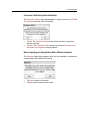
Installing Trimble Access Installation
Manager
To Install Trimble Access Installation Manager:
1.
2.
3.
4.
5.
6.
Turn On your Trimble Rugged Tablet Computer to install the Windows
operating system.
Once completed, turn On the WIFI radio(*).
Install the latest Windows updates.
On your Trimble Rugged Tablet Computer, enter www.trimble.com/taim
into the Internet browser.
And then tap Downloads / Trimble Access Installation Manager.
Click Run and then follow the instructions in the installation wizard to
download the Trimble Installation Manager onto your Trimble Rugged
Tablet Computer.
Note: (*) For more information regarding to how to turn On the WIFI radio,
please refer to the Trimble Rugged Tablet Computer documentation.
Installing and Updating Trimble Access
To Install and Update Trimble Access:
1.
2.
Start button on the taskbar and then All Programs / Trimble
Tap the
Access Installation Manager. Once running, the Trimble Access
Installation Manager contacts the Trimble hosted server to check for any
available updates.
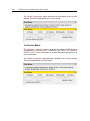
Select the software that you want to install or update on your Trimble
Rugged Tablet Computer:
If a component is already up-to-date with the latest version, it is not
available to select.
If a component is compulsory, the text is maroon and you cannot
de-select the item.
3.
Tap Start. The Trimble Access Installation Manager downloads and
installs the license file and the selected components.
Note:
You need to have an Internet connection on your Trimble Rugged Tablet
Computer.
If you are not licensed to install a particular item, it does not appear in the
list.
Getting Started
Licensing Trimble Access and Components
Every Trimble Access application must be licensed to be able installed and
operated on your Trimble Rugged Tablet Computer. The license file is hosted
on the Trimble hosted sever. You must download it through Trimble Access
Installer Manager.
When you purchase an additional component, extend your existing license,
the license file is then updated on the Trimble hosted server. You need to
download the new license file.
CHAPTER 2
Using Trimble Access
Trimble Access is a software program which offers survey teams a new
approach to surveying that expedites data collection, processing, analysis,
and delivery through improved workflows, collaboration and control.
23
Starting Trimble Access
To Start Trimble Access:
1.
2.
Start button on the taskbar and then All Programs / Trimble /
Tap the
Trimble Access For Tablet PC / Trimble Access.
Or double-tap the Trimble Access icon on your desktop.
If Trimble Access has been started for the first time, the Trimble
Access Home Page opens with a message* prompting you to
choose the type of instrument to be connected to. All Instrument
Tools (like On-site Video Calibration, Auto-Test, etc.) are dimmed.
If Trimble Access has not been started for the first time, it attempts
a connection to the last type of instrument you have used.
Note: (*) You need close the message by tapping OK to be able to choose an
instrument type.
24
Trimble Access for Spatial Imaging User's Guide
Exiting Trimble Access
To Exit Trimble Access:
1.
2.
3.
button. A dialog opens.
Tap the Close
Tap Yes. The Trimble Access program closes.
Tap No. The Trimble Access program remains open.
Using Trimble Access
About Trimble Access
On the Home Page, tapping the Home Page
button will make the About
dialog appeared. This dialog lists the version of Trimble Access you are using
and the plug-ins that are inside. For each, you have the Type of License, the
Date of Expiration and the Version.
26
Trimble Access for Spatial Imaging User's Guide
Understanding Trimble Access's Concepts
Trimble Access is based on three types of Jobs. The workflow of each Job is
a series of Steps and Sub-Steps and each workflow differs from another.
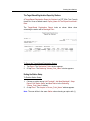
Having an Overview of a Job
Workflow
You can have an overview of where you currently are in a Job workflow
thanks to the Step Bar. The icon of the current Job is placed at the beginning
of the Step Bar. The Accomplished Step is in white while the Current Step is
in yellow. The Not Already Accomplished Step(s) is (or are) not available yet.
Note: There are no Sub-Steps in the Step Bar.
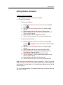
Going Backwards to a Step
To Go Backwards to a Step:
In the Step Bar, tap an Accomplished Step (step in white before the
Current Step (in yellow)).
Note: If the current step is not completed, going backwards to a step will
invalidate it.
Going Forwards to a Step
To Go Forwards to a Step:
1.
2.
In the Step Bar, tap the Current Step.
Or tap an Accomplished Step if there is more than one before the
Current Step.
Using Trimble Access
Browsing Through a Step
In a given Sub-Step, the Back and Next buttons when enabled means that
this Sub-Step requires an input or can be left as it without any input. When
the Next button is dimmed; the user has to fill in this Sub-Step with
parameters before the button becomes enabled. When the Back button is
dimmed; it is because the user is e.g. at the first Sub-Step of a Step. Going
back is forbidden.
When both the Back and Next buttons are dimmed; it is because the SubStep is in progress. When there are no buttons; the user has to make a
choice in order to access to a Step (or Sub-Step).
The Back and Next buttons can become respectively Cancel and (Start or
Done). Cancel means that the user can abort the current Step (or Sub-Step).
Start launches the Sub-Step and Done validates it.
Going Backwards to a Sub-Step
To Go Backwards to a Sub-Step:
Tap the Back button next to the Step Bar.
Going Forwards to a Sub-Step
To Go Forwards to a Sub-Step:
Tap the Next button next to the Step Bar.
28
Trimble Access for Spatial Imaging User's Guide
Going Back to the Trimble Access
Home Page
Inside a job workflow, you can go back to the Trimble Access Home Page at
any time by tapping the Home Page
button.
CHAPTER 3
Setting up a Network Connection
Before being able to work with an instrument, you need to setup a network
connection which is a set of information that enables your Trimble Rugged
Tablet Computer to connect to it.
You can connect to a Trimble GX instrument through an Ethernet cable using
an USB/RJ45 adapter or through Wi-Fi. You can only connect to a Trimble
CX instrument through an Ethernet cable using an USB/RJ45 adapter. In all
cases, Trimble Access uses a TCP/IP protocol that needs to be configured.
31
Configuring the TCP/IP Settings for a
Wireless Network Connection
To Configure the TPC/IP Settings for a Wireless Network Connection:
1.
2.
3.
4.
5.
6.
7.
8.
9.
10.
11.
12.
13.
Tap the
Wireless LAN button*. The Control Panel \ Network
Connections window opens.
Tap the Wireless Network Connection icon. A Mouse Icon in
transparency appears next to it.
Tap on the right button of the Mouse Icon. A pop-up menu drops down.
Tap Properties. The User Account Control dialog opens and prompts to
Continue (or Cancel) the action.
Tap the Continue button. The Wireless Network Connection Properties
dialog opens.
In the Networking tab, select Internet Protocol Version 4 (TCP/IPv4).
Tap the Properties button. The Internet Protocol Version 4 (TPC/IPv4)
Properties dialog opens.
In the General tab, check the "Use the following IP Address" option.
Input 192.0.4.X** in the IP Address field.
Input 255.255.255.0 in the Subnet Mask field.
Tap OK. The Internet Protocol Version 4 (TPC/IPv4) Properties dialog
closes.
Tap Close. The Wireless Network Connection Properties dialog closes.
. The Control Panel \ Network Connections window closes.
Tap
Note:
(*) First start Trimble Access.
(**) X could be anything between 0 and 255 except 0, 1, 10 and 255.
Use the Input Panel to enter the settings. Please, refer to the Trimble
Rugged Tablet Computer documentation on the use of the Input Panel.
32
Trimble Access for Spatial Imaging User's Guide
Configuring the TPC/IP Settings for a Local
Area Connection
To Configure the TPC/IP Settings for a Local Area Connection:
1.
2.
3.
4.
5.
6.
7.
8.
9.
10.
11.
12.
13.
Tap the
Wireless LAN button*. The Control Panel \ Network
Connections window opens.
Tap the Local Area Connection icon. A Mouse Icon in transparency
appears next to it.
Tap the right button of the Mouser Icon. A pop-up menu drops down.
Tap Properties. The User Account Control dialog opens and prompts to
Continue (or Cancel) the action.
Tap the Continue button. The Local Area Connection Properties dialog
opens.
In the Networking tab, select Internet Protocol Version 4 (TCP/IPv4).
Tap the Properties button. The Internet Protocol Version 4 (TPC/IPv4)
Properties dialog opens.
In the General tab, check the "Use the following IP Address" option.
Input an address** in the IP Address field.
Input 255.255.255.0 in the Subnet Mask field.
Tap OK. The Internet Protocol Version 4 (TPC/IPv4) Properties dialog
closes.
Tap Close. The Local Area Connection Properties dialog closes.
. The Control Panel \ Network Connections dialog closes.
Tap
Note:
(*) First start Trimble Access.
(**) If using a Trimble GX instrument, the address should be 192.0.4.X
where X could be anything between 0 and 255 except 0, 1, 10 and 255.
(**) If using a Trimble CX instrument, the address should be
192.168.100.X where X must be equal to 1.
Use the Input Panel to enter the settings. Please, refer to the Trimble
Rugged Tablet Computer documentation on the use of the Input Panel.
Setting up a Network Connection
Setting up a Wi-Fi Connection to the
Trimble GX instrument
Once you have a network connection, you can setup a connection to the
Trimble GX instrument.
To Setup a Wi-Fi Connection to the Trimble GX instrument:
1.
2.
3.
4.
5.
6.
7.
8.
9.
In the Network Connections window, tap the
Wireless Network
Connection icon to select it. The
Connect To icon appears.
Tap the Connect To icon. The Connect to a Network dialog opens.
If required, tap the Refresh Network List icon.
Choose an access point connected to a Trimble GX instrument from the
list.
Tap the Connect button. The "TRIMBLE_Serial_Number is an unsecured
network" message appears as well as the Connect Anyway button.
Tap the Connect Anyway button. The "Connecting to
TRIMBLE_Serial_Number" and "Successfully Connected to
TRIMBLE_Serial_Number" messages appear.
Tap Close. The Connect to a Network dialog closes.
If required, close the Network Connections window.
If required, close the Network Connections and Network and Sharing
Center windows.
Tip: You can first tap the
Control Panel from Settings.
Start button in your Windows® desktop, select
34
Trimble Access for Spatial Imaging User's Guide
Checking the Windows Firewall
A Firewall is a security system when may set restriction on what information
is communicated from your Trimble Rugged Tablet Computer to your
instrument and vice versa. The Windows Firewall protection is by-default On.
To Check the Windows Firewall:
1.
2.
3.
4.
Tap the
Start button in your Windows® desktop. A menu bar pops
up.
Select Settings \ Control Panel from the menu bar. The Control Panel
window appears.
In e.g. Windows' Classic View, double-tap the Security Center icon. The
Windows Security Center window appears.
You may see Off in the Firewall line.
Setting up a Network Connection
Turning Off the Windows Firewall
To be able to run Trimble Access, you need to turn off the Windows Firewall.
To Turn Off the Windows Firewall:
1.
2.
3.
4.
5.
6.
7.
8.
In the Windows Security Center window, tap the Windows Firewall icon
in left panel. The Windows Firewall window appears.
Tap either Change Settings or Turn Windows Firewall On or Off. The
User Account Control dialog appears and prompts to Continue (or
Cancel) the action.
Tap the Continue button. The User Account Control dialog disappears
while the Windows Firewall Settings dialog opens.
Check the Off (Not Recommended) option.
Tap OK. The Windows Firewall Settings dialog closes.
Tap
. The Windows Firewall window closes.
Tap again
. The Windows Security Center window closes.
. The Control Panel window closes.
Tap again
CHAPTER 4
Connecting to an Instrument
You can connect to an instrument in two ways. First is an automatic
connection when you start Trimble Access. Second is a manual connection
when the connection has been lost.
Note: In the first case, if Trimble Access has been started for the first time, no
(automatic) connection to an instrument will occur. If this is not the first time;
Trimble Access attempts an automatic connection to the last type of
instrument.
39
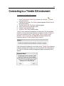
Connecting to a Trimble GX instrument
To Connect to a Trimble GX instrument:
1.
2.
3.
4.
5.
6.
button
In the Trimble Access Home Page, browse to the Settings
using the scroll bar.
Tap the Settings button. The Settings window appears with the General
tab open by-default.
Tap the Network tab. The Network window appears.
Tap on the Instrument pull-down arrow.
Choose GX as instrument type.
Tap Done. The Settings window closes.
Trimble Access executes two operations in batch mode. The first operation
consists of running an automatic detection procedure to find the Trimble GX
instrument connected to your Trimble Rugged Tablet Computer. Once
detected, Trimble Access tries to establish a connection between the
instrument and your Trimble Rugged Tablet Computer.
If the instrument's IP address is not correctly set-up, Trimble Access displays
a warning message and prompts you to try to reconnect to the instrument or
not. Tap No to close the warning message and update consequently the IP
address.
40
Trimble Access for Spatial Imaging User's Guide
If an instrument is already connected to your Trimble Rugged Tablet
Computer, Trimble Access displays the warning message below. Tap Ok to
close the warning message.
The second procedure consists of checking the driver and firmware versions
and their compatibility. On some rare occasions, the driver and firmware
versions may not be fully compatible. Trimble Access will prompt you to
update the firmware. Note that selecting No will not prevent you from working
with Trimble Access, but may cause some functions (or features) to remain
inactive.
Note: Follow the steps from 1 to 6 only if Trimble Access has been started for
the first time.
Connecting to an Instrument
Updating the Trimble GX instrument's
Firmware
The Firmware Update dialog opens. Trimble Access lists the Trimble GX
instrument with its name and reference number as well as the firmware and
driver versions and a conflicting version (if present).
To Update the Firmware:
1.
Tap Yes. Trimble Access displays a warning message and prompts you
to not disconnect or switch the Trimble GX instrument off while the set-up
is in doing.
42
Trimble Access for Spatial Imaging User's Guide
2.
3.
Tap OK. The warning message closes. The Trimble GX instrument's
firmware updating is carried out in two stages. First concerns the
firmware updating. Second is about the instrument rebooting.
Tap OK. The Firmware Update dialog closes.
Note:
Ensure also that the power supply box's cable does not prevent the
Trimble GX instrument from rotating.
The Trimble GX instrument rotates around its base 180° clockwise
looking for its origin and then 360° anticlockwise if the origin is not found
on the first turn. To prevent the Trimble GX instrument from rotating
excessively, ensure that the specifically marked Trimble GX instrument
leg is set at the left of the porthole.
Connecting to an Instrument
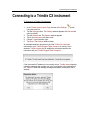
Connecting to a Trimble CX instrument
To Connect to a Trimble CX instrument:
1.
2.
3.
4.
5.
6.
button
In the Trimble Access Home Page, browse to the Settings
using the scroll bar.
Tap the Settings button. The Settings window appears with General tab
open by-default.
Tap the Network tab. The Network window appears.
Tap on the Instrument pull-down arrow.
Choose CX as instrument type.
Tap Done. The Settings window closes.
An automatic detection procedure to find the Trimble CX instrument
connected to your Trimble Rugged Tablet Computer is running. Once
detected, Trimble Access tries to establish a connection between the
instrument and your Trimble Rugged Tablet Computer.
If the instrument's IP address is not correctly set-up, Trimble Access displays
a warning message and prompts you to try to reconnect to the instrument or
not. Tap No to close the warning message and update consequently the IP
address.
44
Trimble Access for Spatial Imaging User's Guide
If an instrument is already connected to your Trimble Rugged Tablet
Computer, Trimble Access displays the warning message below. Tap Ok to
close the warning message.
Note: Follow the steps from 1 to 6 only if Trimble Access has been started for
the first time.
Connecting to an Instrument
Checking the Connection Status
You can visually check if your Trimble Rugged Tablet Computer is connected
(or not) to an instrument thanks to the Connection button located at the title
bar of Trimble Access.
The Connection button when taking the following color means that no
instrument is connected to your Trimble Rugged Tablet Computer or the
connection has been lost. In this state, Trimble Access does not look for
an instrument.
The Connection button when flashing (from to and vice versa)
means that Trimble Access is looking for an instrument.
The Connection button when taking the following color means that an
instrument is connected to your Trimble Rugged Tablet Computer.
46
Trimble Access for Spatial Imaging User's Guide
Requesting a Connection to an Instrument
At any time, when the connection to an instrument is lost or when you are
simply not connected; you can request for a connection.
To Request a Connection to an Instrument:
1.
2.
3.
Tap the Connection button. The Connection Request dialog opens.
Tap Yes. Trimble Access will attempt a connection to your instrument.
Tap No. The connect request is aborted.
Note: If an instrument is already connected to your Trimble Rugged Tablet
Computer, tapping the Connection button has no effect.
Connecting to an Instrument
Checking the Wireless Signal Strength
You can visually check the Wireless signal strength thanks to the Wireless
LAN
button located at the title bar of Trimble Access. The signal
strength is symbolized by five bars from Low to Strong.
Note: When connecting to the instrument through an Ethernet cable using a
USB/RJ54 adapter, the Wireless LAN button may have two states:
Connectivity On or Connectivity Off.
48
Trimble Access for Spatial Imaging User's Guide
Checking the TPC/IP Settings
To Check the TPC/IP Settings:
1.
Wireless LAN button*. The Control Panel \ Network
Tap the
Connections window opens.
2.
Tap the
Wireless Network Connection (or
Local Area
Connection) icon. A Mouse Icon in transparency appears next to it.
3. Tap on the right button of the Mouse Icon. A pop-up menu drops down.
4. Tap Properties. The User Account Control dialog opens and prompts to
Continue (or Cancel) the action.
5. Tap the Continue button. The Wireless Network Connection Properties
(or Local Area Connection Properties) dialog opens.
6. In the Networking tab, select Internet Protocol Version 4 (TCP/IPv4).
7. Tap the Properties button. The Internet Protocol Version 4 (TPC/IPv4)
Properties dialog opens.
8. Verify that the "Use the following IP Address" option is checked as well
as the address and the numbers respectively in the IP Address and
Subnet Mask fields.
9. Tap OK. The Internet Protocol 4 (TPC/IPv4) Properties dialog closes.
10. Click Close. The Wireless Network Connection Properties (or Local Area
Connection Properties) dialog closes.
11. Tap
. The Control Panel \ Network Connections dialog closes.
Note:
(*) First start Trimble Access.
For a Trimble GX instrument, the IP Address and Subnet Mask should be
respectively 192.0.4.X and 255.255.255.0. X could be anything between
0 and 255 except 0, 1, 10 and 255.
For a Trimble CX instrument, the IP Address and Subnet Mask should be
respectively 192.168.100.X and 255.255.255.0. X could be anything
except to the Trimble CX instrument (serial) number.
Connecting to an Instrument
The Laser Safety Standards
All Trimble GX instruments comply with the performance requirements of US
FDA 21 CFR §1040.10 as a Class 2 laser product, and are therefore labeled
in accordance with the requirements of this standard. They also comply with
the performance requirements of IEC 60825-1 as a Class 3R laser product
and are therefore labeled as follows in accordance with the requirements of
this standard.
All Trimble CX instruments comply with the performance requirements of IEC
60825-1 as a Class 3R laser product and are therefore labeled in accordance
with the requirements of this standard.
Choosing a Laser Safety Standard
The Laser Safety dialog opens once an instrument* has been detected and a
connection (to the instrument) is in progress.
To Choose a Laser Safety Standard:
1.
2.
In the Laser Safety dialog, choose between US Standard 21 CFR
§1041.10 and International Standard IEC 60825-1, Edition 1.2.
Tap the OK button. The Laser Safety dialog closes.
Note:
(*) The Laser Safety dialog will not open if using a Trimble CX
instrument.
Be aware that the "Don't Show Me This Message Again" option is
checked by default. If you decide to leave it checked; the chosen
Standard cannot then be changed later as the Laser Safety dialog will not
appear again.
50
Trimble Access for Spatial Imaging User's Guide
Viewing the Laser Safety Class
If the International Standard IEC 60825-1 (Edition 1.2) has been chosen; the
Laser Safety Class* under which you intend to operate will display in the
Estimation and Safety Parameters panel when choosing the Conventional
Resolution as Resolution Type.
Note: (*) For a Trimble GX instrument, it may be (2M or 3R). For a Trimble
CX instrument, it will only be 3R.
CHAPTER 5
Leveling and Compensating an
Instrument
Leveling an instrument is the action of adjusting its vertical position using to
the three leveling screws of the tribrach*. Leveling can be done after the
instrument has been detected and connected to your Trimble Rugged Tablet
Computer or later when you need to do it. In the latter case, you need to
select the related command.
Note: (*) Located below the instrument. Please, refer to the user manual that
comes with your instrument for more information about how adjusting the
tribrach leveling screws. We assume here that the instrument has been
already setup.
53
Leveling a Trimble GX instrument
The electronic bubble in the Leveling window contitues as a visual control to
check if your instrument is leveled (or not). It may have three states: Out of
Range, Yellow and Green.
In addition to the electronic bubble, the Leveling window displays the
Trunnion and Sighting information. The horizontal rotation's axis of the
instrument is called Trunnion while its sighting direction for acquiring cloud
data is called Sighting and both are expressed in degrees, minutes and
seconds. The Compensator (when activated) is a feature to level-compensate
automatically for all 3D points.
Note: The Leveling, Trunnion and Sighting information are available once the
Leveling window appears.
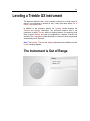
The Instrument is Out of Range
54
Trimble Access for Spatial Imaging User's Guide
When the instrument is out of range, the electronic bubble is as shown above.
The Compensator feature (when the instrument rotates) is not enabled
because not guaranteed; the Disable Compensator option is not enabled. In
this case, tap the Ok button to close the Error message and adjust the
instrument's vertical position using the three leveling screws of the tribrach
below the instrument until the electronic bubble level becomes first yellow and
then green and centered.
Note: You can leave the instrument as it is (out of range) and directly tap
Next.
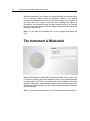
The Instrument is Misleveled
When the instrument is misleveled, the electronic bubble color is yellow. The
Compensator feature (when the instrument rotates) is not enabled because
not guaranteed; the Disable Compensator option is not enabled. In this case,
adjust the instrument's vertical position using the three leveling screws of the
tribrach below the instrument until the electronic bubble becomes first green
and then centered.
Note: You can leave the instrument as it is (misleveled) and directly tap Next.
Leveling and Compensating an Instrument
The Instrument is Leveled
When the instrument is leveled, the electronic bubble color is green and
centered. The Compensator feature (when the instrument rotates) is enabled
because guaranteed, the Disable Compensator option is enabled and
unchecked by default.
56
Trimble Access for Spatial Imaging User's Guide
Leveling a Trimble CX instrument
The electronic bubble in the Leveling window contitues as a visual control to
check if your instrument is leveled (or not). It may only have two states:
Yellow or Green.
In addition to the electronic bubble, the Leveling window displays the
Trunnion and Sighting information. The horizontal rotation's axis of the
instrument is called Trunnion while its sighting direction for acquiring cloud
data is called Sighting and both are expressed in degrees, minutes and
seconds. The Compensator (when activated) is a feature to level-compensate
automatically for all 3D points.
Note: The Leveling, Trunnion and Sighting information remain unavailable
until the Tilt measurement has been performed.
Measuring the Tilt
Before measuring the Tilt and when the measurement is in progress, the
Disable Compensator option is by default checked and grayed-out. Both the
Trunnion and Sighting information are unavailable.
To Measure the Tilt:
Tap the Measure Tilt button. The Trimble CX instrument performs four
measurements. It first turns 270° anticlockwise to make the first
measurement, then 90° clockwise for the second, again 90° clockwise to
the third and finally 90° clockwise to the last. Once completed, the
Disable Compensator option becomes then enabled and un-checked.
Both the Trunnion and Sighting information are displayed.
Note: The measurements (performed by the instrument) may take some time.
Leveling and Compensating an Instrument
The Instrument is Misleved
When the instrument is misleveled, the electronic bubble color is yellow. The
Compensator feature (when the instrument rotates) is not enabled because
not guaranteed; the Disable Compensator option is not enabled. In this case,
adjust the instrument's vertical position using the three leveling screws of the
tribrach below the instrument and measure the Tilt again until the electronic
bubble becomes first green and then centered.
Note: You can leave the instrument as it is (misleveled) and directly tap Next.
58
Trimble Access for Spatial Imaging User's Guide
The Instrument is Leveled
When the instrument is leveled, the electronic bubble color is green and
centered. The Compensator feature (when the instrument rotates) is enabled
because guaranteed, the Disable Compensator option is enabled and
unchecked by default.
Leveling and Compensating an Instrument
Activating and Deactivating the
Compensator
Activating the Compensator
You can decide to automatically level-compensate for all 3D points.
To Activate the Compensator:
1.
2.
Keep the Disable Compensator option unchecked.
Tap Next.
When using a Trimble GX instrument, the Atmospheric Correction
window appears.
When using a Trimble CX instrument, the Trimble Access Home
Page appears.
Deactivating the Compensator
You can decide to not automatically level-compensate for all 3D points.
To Deactivate the Compensator:
1.
2.
Check the Disable Compensator option.
Tap Next.
When using a Trimble GX instrument, the Atmospheric Correction
window appears.
When using a Trimble CX instrument, the Trimble Access Home
Page appears.
60
Trimble Access for Spatial Imaging User's Guide
Correcting the Atmospheric Parameters
The Trimble GX instrument is based on the EDM (Electronic Distance
Measurement) for collecting points. The distance measurement is function of
the velocity of light in the atmosphere and the velocity of light depends on the
refractive index of air, temperature, pressure and humidity. The Atmospheric
Correction feature in Trimble Access enables to apply corrections to the
distance measurement - expressed in PPM (Part Per Million) - according to
these atmospheric parameters. The Trimble GX instrument has been
calibrated so that no correction is applied at 20°C and 1013.25 mBar.
You can decide to apply (or not) a correction after auto-detecting and leveling
the instrument connected to your Trimble Rugged Tablet Computer. You can
apply several corrections to a project.
Inputting a PPM Value
To Input a PPM Value:
1.
2.
3.
4.
In the Atmospheric Correction window, tap in the PPM (Keyed In) field.
An on-screen keypad appears.
Input a value in the PPM (Keyed In) field.
Tap Ok. The on-screen keypad disappears.
Tap Done. The Atmospheric Correction window closes.
Leveling and Compensating an Instrument
Computing a PPM Value
To Compute a PPM Value:
1.
2.
3.
4.
5.
6.
7.
In the Atmospheric Correction window, check the Set Atmospheric
Temperature and Pressure option. The Pressure and Temperature fields
appear below the option.
Tap in the Pressure field. An on-screen keypad appears.
Input a value in the Pressure field. The default unit of measurement is
setup in millibars; you do not need to enter "mBar" after the value.
Tap the Tab button. The on-screen keypad jumps to the Temperature
field for editing.
Input a value in the Temperature field. The default unit of measurement
is the one set in Settings. If Celsius has been chosen; you do not need to
enter "°C" after the value. If Fahrenheit has been chosen, you do not
need to enter "°F" after the value.
Tap Ok. The on-screen keypad disappears.
Tap Done. The Atmospheric Correction window closes.
Keeping the Atmospheric Correction
Deactivated
You can decide to not apply a correction to your project. In this case, tap the
Done button in the Atmospheric Correction window without inputting a value
in the PPM (Keyed In) field.
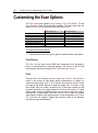
CHAPTER 6
Creating Jobs
To record data acquired by an instrument, you must create (or have) a job
(open). There are several types of jobs in Trimble Access: General Scanning,
Volumes and DTM. A job cannot come alone. It is always associated to a
project inside which you can mix different types of jobs.
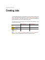
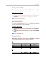
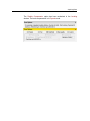
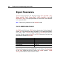
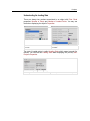
The table below lists the types of job you can have according to the
instrument you are using.
GX Instrument*
CX Instrument
General Scanning
Volumes
DTM
Note: (*) The Trimble GX instrument needs to be a GX Advanced™.
Otherwise, some of the applications like the DTM cannot be used.
65
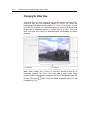
A General Scanning Job
The purpose of the General Scanning job is to first control a Trimble
instrument with the Trimble Rugged Tablet Computer and then acquire data
(Point Cloud(s) or Point(s)**) and Images (if needed).
To Create a General Scanning Job:
1.
2.
In the Trimble Access Home Page, tap the General Scanning
button.
Do one of the following:
If there is no project; the Create a New Project window opens. A new
project is created with a default name "Project".
If there is at least one (not loaded) project (with or without station(s)
already setup); the Project Manager window appears and you have
choice among Load "Last_Project_Name", Load an Existing Project and
Create a New Project.
If there is a project already loaded (but without station(s) inside); the New
Station window appears.
If there is a project already loaded (but with station(s) already setup or
not); the Stationing window* appears.
Note:
(*) The Stationing window name may change according to the Station
Setup you used. It can be Stationing "Known_Point_Name", Stationing
"Station_Point_Name" or Stationing "Station_Name".
(**) Only with a Trimble GX instrument. If using a Trimble CX instrument,
you can only acquire Point Cloud(s) and/or Image(s).
Editing Newly Created Project Name
To Edit the Newly Created Project Name:
1.
2.
3.
4.
5.
If you wish to create a new project with the default name, tap Next.
Otherwise, tap inside the New Project Name field. An on-screen
keyboard appears.
Input a new name in the New Project Name field.
Tap Ok to validate. The on-screen keyboard disappears.
Tap Next. The New Station window appears.
66
Trimble Access for Spatial Imaging User's Guide
Loading Last Project
To Load the Last Project:
Tap Load "Last_Project_Name". The Stationing window* appears.
Note:
(*) Only if the last station of the loaded project has been setup.
Otherwise, the New Station window appears in place.
(*) The Stationing window name may change according to the Station
Setup you used. It can be Stationing "Known_Point_Name", Stationing
"Station_Point_Name" or Stationing "Station_Name".
Loading Existing Project
To Load an Existing Project:
1.
2.
3.
Tap Load an Existing Project. The Projects window appears.
Select a project by tapping it.
Tap Done. The Projects window closes and the Stationing window*
appears.
Tip: You can also select and double-tap a project to load it.
Note:
(*) Only if the last station of the loaded project has been setup.
Otherwise, the New Station window appears in place.
(*) The Stationing window name may change according to the Station
Setup you used. It can be Stationing "Known_Point_Name", Stationing
"Station_Point_Name" or Stationing "Station_Name".
Creating Jobs
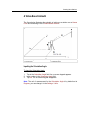
A Volume Job
The purpose of the Volume job is to calculate a volume between the acquired
data (Point Cloud) and a Reference Plane. The Volume job is based on a grid
method and the result is represented in the View 3D by a graph of vertical
color lines.
To Create a Volume Job:
1.
2.
In the Trimble Access Home Page, tap the Volumes
Do one of the following:
button.
If there is no project; the Create a New Project window opens. A new
project is created with a default name "Project".
If there is at least one (not loaded) project (with or without station(s)
already setup); the Project Manager window appears and you have
choice among Load "Last_Project_Name", Load an Existing Project and
Create a New Project.
If there is a project already loaded (but without station(s) inside); the New
Station window appears.
If there is a project already loaded (but with station(s) already setup or
not); the Stationing window* appears.
Note:
(*) The Stationing window name may change according to the Station
Setup you used. It can be Stationing "Known_Point_Name", Stationing
"Station_Point_Name" or Stationing "Station_Name".
And if a Job Resolution has been already defined. Otherwise, the Define
Job Resolution window appears.
You can have access to the job even if the used instrument is not a GX
Advanced™ (with the SureScan™ functionality). The current project is
not aborted but created in the Project Tree.
68
Trimble Access for Spatial Imaging User's Guide
Editing Newly Created Project Name
To Edit the Newly Created Project Name:
1.
2.
3.
4.
5.
If you wish to create a new project with the default name, tap Next.
Otherwise, tap inside the New Project Name field. An on-screen
keyboard appears.
Input a new name in the New Project Name field.
Tap Ok to validate. The on-screen keyboard disappears.
Tap Next. The Define Job Resolution window appears.
Loading Last Project
To Load the Last Project:
Tap Load "Last_Project_Name". The Stationing window* appears.
Note:
(*) Only if the last station of the loaded project has been setup.
Otherwise, the New Station window appears in place.
And if a Job Resolution has been already defined. Otherwise, the Define
Job Resolution window appears.
(*) The Stationing window name may change according to the Station
Setup you used. It can be Stationing "Known_Point_Name", Stationing
"Station_Point_Name" or Stationing "Station_Name".
Creating Jobs
Loading Existing Project
To Load an Existing Project:
1.
2.
3.
Tap Load an Existing Project. The Projects window appears.
Select a project by tapping it.
Tap Done. The Projects window closes and the Stationing window*
appears.
Tip: You can also select and double-tap a project to load it.
Note:
(*) Only if the last station of the loaded project has been setup.
Otherwise, the New Station window appears in place.
And if a Job Resolution has been already defined. Otherwise, the Define
Job Resolution window appears.
(*) The Stationing window name may change according to the Station
Setup you used. It can be Stationing "Known_Point_Name", Stationing
"Station_Point_Name" or Stationing "Station_Name".
70
Trimble Access for Spatial Imaging User's Guide
A DTM Job
The purpose of the DTM (stood for Digital Terrain Model) job is to create a
triangulated mesh from the acquired data (Point Cloud).
To Create a DTM Job:
1.
2.
In the Trimble Access Home Page, tap the DTM
Do one of the following:
button.
If there is no project; the Create a New Project window opens. A new
project is created with a default name "Project".
If there is at least one (not loaded) project (with or without station(s)
already setup); the Project Manager window appears and you have
choice among Load "Last_Project_Name", Load an Existing Project and
Create a New Project.
If there is a project already loaded (but without station(s) inside); the New
Station window appears.
If there is a project already loaded (but with station(s) already setup or
not); the Stationing window* appears.
Note:
(*) The Stationing window name may change according to the Station
Setup you used. It can be Stationing "Known_Point_Name", Stationing
"Station_Point_Name" or Stationing "Station_Name".
And if a Job Resolution has been already defined. Otherwise, the Define
Job Resolution window appears.
You can have access to the job even if the used instrument is not a GX
Advanced™ (with the SureScan™ functionality). The current project is
not aborted but created in the Project Tree.
Editing Newly Created Project Name
To Edit the Newly Created Project Name:
1.
2.
3.
4.
5.
If you wish to create a new project with the default name, tap Next.
Otherwise, tap inside the New Project Name field. An on-screen
keyboard appears.
Input a new name in the New Project Name field.
Tap Ok to validate. The on-screen keyboard disappears.
Tap Next. The Define Job Resolution window appears.
Creating Jobs
Loading Last Project
To Load the Last Project:
Tap Load "Last_Project_Name". The Stationing window* appears.
Note:
(*) Only if the last station of the loaded project has been setup.
Otherwise, the New Station window appears in place.
And if a Job Resolution has been already defined. Otherwise, the Define
Job Resolution window appears.
(*) The Stationing window name may change according to the Station
Setup you used. It can be Stationing "Known_Point_Name", Stationing
"Station_Point_Name" or Stationing "Station_Name".
Loading Existing Project
To Load an Existing Project:
1.
2.
3.
Tap Load an Existing Project. The Projects window appears.
Select a project by tapping it.
Tap Done. The Projects window closes and the Stationing window*
appears.
Tip: You can also select and double-tap a project to load it.
Note:
(*) Only if the last station of the loaded project has been setup.
Otherwise, the New Station window appears in place.
And if a Job Resolution has been already defined. Otherwise, the Define
Job Resolution window appears.
(*) The Stationing window name may change according to the Station
Setup you used. It can be Stationing "Known_Point_Name", Stationing
"Station_Point_Name" or Stationing "Station_Name".
72
Trimble Access for Spatial Imaging User's Guide
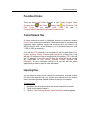
A Job Resolution
In Volumes, a Job Resolution is first used as a SureScan™ parameter for
acquiring data (Point Cloud) in a job and then as a grid resolution in
computing a Delivery from the acquired data.
In DTM, a Job Resolution is only used as a SureScan™ parameter for
acquiring data.
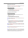
Defining a Job Resolution
To Define a Job Resolution:
1.
2.
3.
4.
Tap in the Job Resolution field. An on-screen keypad appears.
Input a value in the Job Resolution field.
Tap Ok. The on-screen keypad disappears.
Tap Next. The New Station window appears.
Modifying a Job Resolution
You can modify a Job Resolution after defining it in the New Station window
or once a Point Cloud data has been acquired by tapping Parameters on the
Step Bar.
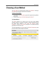
CHAPTER 7
Creating New Stations
A Station is composed of all Scans obtained from a fixed position of an
instrument. The way it will be created in Trimble Access varies with the
instrument leveling.
Note: A Station is always associated with a unique instrument. When the
user attempts to complete an existing Station with a different instrument in
type (GX or CX) or in serial number (for the given type), he will be prompted
to create a new Station (or not).
75
When the Instrument is Leveled
To Create a New Station:
1.
2.
3.
Tap Station Setup. The Create Station Known Point window appears.
Or tap Resection. The Set Station Parameters window appears.
Or tap No Station Setup. The Set Station Parameters window appears.
76
Trimble Access for Spatial Imaging User's Guide
When the Instrument is Misleveled
To Create a New Station:
1.
2.
3.
Tap Level the Instrument. The Leveling window appears.
Or tap 3 Backsight Based. The Set Station Parameters window appears.
Or tap No Station Setup. The Set Station Parameters window appears.
Creating New Stations
Setting up a Station with Known
Coordinates or Azimuth
The Station Setup method consists of leveling the instrument, setting it up
Over a Known Point (also called Control Point) and orienting it using a known
Backsight Point, an unknown Backsight Point or a Video-Based Azimuth.
Creating a Station Known Point
A Known Point is mainly a point on the ground for which the coordinates are
known. Theses coordinates are three-dimension coordinates expressed in the
Cartesian coordinate system*. They can be manually entered or can come
from an imported file.
Note: (*) If Cartesian X, Y, Z has been chosen in the Settings \ Units.
To Create a Station Known Point:
1.
2.
3.
4.
Define a Known Point Name.
Input Know Point Coordinates.
And/or set the Station Parameters.
Tap Next. The Orientate Station With window appears.
Defining a Known Point Name
By default, a Known Point Name is a Number which starts at One and is
incremented of One each time a new Known Point is added.
To Define a Known Point Name:
1.
2.
3.
Keep the default name or tap in the Known Point Name field. An onscreen keyboard appears.
Enter a new name in the Known Point Name field.
Tap Ok. The on-screen keyboard closes by its own.
78
Trimble Access for Spatial Imaging User's Guide
Inputting Known Point Coordinates
To Input Known Point Coordinates:
1.
2.
3.
4.
Tap in the X field. An on-screen numerical pad appears next to the X
field.
Input a value in the X field.
Tap Ok. The on-screen keypad closes by its own.
Repeat the steps from 1 to 3 for the Y and Z fields.
Note: The unit of measurement for X, Y and Z is by default set to Meters; you
can change it in the Settings / Units.
Tip:
The newly created Known Point is put in a list. You may see that list by
tapping Back (once the Create Known Point step has been completed).
Instead tapping Ok, you can also use the Tab button. The on-screen
keypad jumps to the next filed to edit.
Note: The created Known Point is put under a Topographic Station which
name is Control Points. Its related Target (once measured) is created and put
under the current Station.
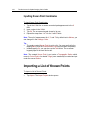
Importing a List of Known Points
To Import a List of Known Points:
Tap Import. The Import Project window opens.
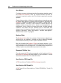
Choosing a Destination Folder
A Destination Folder is a Local Folder in your Trimble Rugged Tablet
Computer drive. You can choose between a pre-defined Local Folder and a
user-defined Local Folder.
Creating New Stations
Pre-defined Folders
There are three Local Folder shortcuts in your Trimble Rugged Tablet
Files Folder,
Desktop and
My Documents. The
Computer drive:
Files
Folder
is
the
default
Local
Folder.
Its
path
is
C:\Users\TablePC\AppData\Local\Trimble\Trimble Access.
Control Network Files
A control network surveyed by traditional surveying instruments contains
Control Points with known coordinates. These points used for georeferencing
registration items (spheres, targets and surveying point) are stored in an
ASCII format file (with *.txt as extension) or in a coordinate format file (with
*.CRD (or CR5) as extension).
A file with the CRD extension is a coordinate file with five data fields (Point
number, Northing, Easting, Elevation and Description) in binary form. A file
with the CR5 extension is also a coordinate file but owned by TDS. A file with
the TXT extension is an ASCII text file. Each line of the text file can contain
any combination of Point number, Northing, Easting, Elevation and
Description. All point information should be on one line with the values
separated by a comma, space or other delineators.
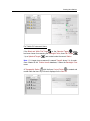
Importing Files
You can import as many control network files as required. A control network
file will not be removed from your project once imported (into the project)
even if the station has been deleted because its setup is not complete.
To Import a File:
1.
2.
3.
Navigate to the drive/ folder where the control network file is located.
Tap on the file name to select it.
Tap Next. The Surveying Network Import Parameters window appears.
80
Trimble Access for Spatial Imaging User's Guide
Setting Surveying Network Import Parameters
The import parameters (Coordinate System and Unit) are those used to
represent the coordinates of Control Points in the imported file.
To Set Surveying Network Import Parameters:
1.
2.
3.
4.
5.
Tap on the Coordinate System pull-down arrow.
Choose among "Cartesian X, Y, Z", "North, West, Elevation", "South,
West, Elevation" and "North, West, Elevation".
Tap on the Unit pull-down arrow.
Choose a unit of measurement from the drop-down list.
Tap Next. The Select Known Point window appears.
All imported Known Points are listed in the Select Known Point window. They
are gathered according to the file they belong to under a Topographic
Station* whose name is the imported file's name.
Note: (*) You may see the Topographic Station with all Known Points under
the Project Tree.
Selecting a Station Known Point
To Select a Station Known Point:
1.
2.
3.
4.
Tap List. The Select Station Known Point window appears.
Select a Known Point by tapping it.
And/or set the Station Parameters.
Tap Next. The Orientate Station With window appears.
Note: The Select Station Known Point window will be empty if there is no
already existed Known Point.
Creating New Stations
Setting the Station Parameters
The Over Known Point method involves measuring the distance which
separates a Known Point from the center of the instrument's mirror. This
distance is called True Height.
To Set the Station Parameters:
Input a value in the Instrument Height* field.
Tip: You can tap Next without inputting a value in the Instrument Height* field
as you can edit its value later.
Note: (*) When using a Trimble GX instrument, the Instrument Height type
(True Height, Bottom Notch Height or Top Notch Height) which appears in the
Set Station Parameters window is the last used one. If the instrument is a CX,
only the True Height is available.
Inputting the True Height
To Input the True Height:
1.
2.
3.
4.
If you only have a True Height value, first tap the pull-down arrow and
change the height type to True Height.
Tap in the True Height field. An on-screen numerical pad appears.
Input a value in the True Height field.
Tap Ok. The on-screen numerical pad disappears.
Note: The unit of measurement for the True Height is by default set to
Meters; you can change it in the Settings / Units.
82
Trimble Access for Spatial Imaging User's Guide
Inputting the Bottom Notch Height
To Input the Bottom Notch Height:
1.
2.
3.
4.
If you only have a Bottom Notch Height value, first tap the pull-down
arrow and change the height type to Bottom Notch Height.
Tap in the Bottom Notch Height field. An on-screen keypad appears.
Input the value in the Bottom Notch Height field.
Tap Ok. The on-screen keypad disappears. The Bottom Notch Height
value will be automatically corrected (a vertical slope distance is applied
to this value).
Note: The unit of measurement for the Bottom Notch Height is by default set
to Meters; you can change it in the Settings \ Units.
Inputting the Top Notch Height
To Input the Top Notch Height:
1.
2.
3.
4.
If you only have a Top Notch Height value, first tap the pull-down arrow
and change the height type to Top Notch Height.
Tap in the Top Notch Height field. An on-screen keypad appears.
Input the value in the Top Notch Height field.
Tap Ok. The on-screen keypad disappears. The Top Notch Height value
will be automatically corrected (two slope distances (vertical and
horizontal) are applied to this value).
Note: The unit of measurement for the Top Notch Height is by default set to
Meters; you can change it in the Settings \ Units.
Creating New Stations
Orientating a Station With
Orientating a station can be done by sighting a known Backsight Point, with
an unknown Backsight Point and an Angle or by giving an Azimuth angle.
To Orientate a Station With:
1.
2.
3.
Tap Known Backsight. The Create Backsight Known Point window
appears.
Or tap Unknown Backsight. The Define Backsight Point Name window
appears.
Or tap Video-Based Azimuth. The Set Station Arbitration Orientation
window appears.
84
Trimble Access for Spatial Imaging User's Guide
A Known Backsight Point
The figure below illustrates the principle of setting-up a station over a Known
Point and orientating it with a known Backsight Point.
1 - Instrument Height
2 - Known Point
3 - Backsight Height
4 - Backsight Point
Creating a Backsight Known Point
A Backsight Point is mainly a point used to orientate a station for which the
coordinates are known. These coordinates are three-dimension coordinates
expressed in the Cartesian coordinate system*. They can be manually
entered or can come from an imported file.
Note: (*) If Cartesian X, Y, Z has been chosen in the Settings / Units.
To Create a Backsight Known Point:
1.
2.
3.
4.
Define a Known Point Name.
Input Know Point Coordinates.
And/or set the Backsight Parameters.
Tap Next. The Measure Backsight Point window appears.
Creating New Stations
Defining a Known Point Name
By default, a Known Point Name is a Number which starts at One and is
incremented of One each time a new Known Point is added.
To Define a Known Point Name:
1.
2.
3.
Keep the default name or tap in the Known Point Name field. An onscreen keyboard appears.
Enter a new name in the Known Point Name field.
Tap Ok. The on-screen keyboard closes by its own.
Inputting Known Point Coordinates
To Input Known Point Coordinates:
1.
2.
3.
4.
Tap in the X field. An on-screen numerical pad appears next to the X
field.
Input a value in the X field.
Tap Ok. The on-screen keypad closes by its own.
Repeat the steps from 1 to 3 for the Y and Z fields.
Note: The unit of measurement for X, Y and Z is by default set to Meters; you
can change it in the Settings / Units.
Tip:
The newly created Known Point is put in a list. You may see that list by
tapping Back (once the Create Known Point step has been completed).
Instead tapping Ok, you can also use the Tab button. The on-screen
keypad jumps to the next filed to edit.
Note: The created Known Point is put under a Topographic Station which
name is Control Points. Its related Target (once measured) is created and put
under the current Station.
Note: The Backsight Azimuth value will be updated according to the input
coordinates or to the selected Backsight Point.
Note: When the input coordinates are not valid, the following warning
message is displayed: "This point cannot be set as Backsight because its
coordinates are on the instrument up axis." You need to tap valid coordinates
to access to the next sub-step. The instrument up axis is 0, 0 and 1.
86
Trimble Access for Spatial Imaging User's Guide
Importing a List of Known Points
To Import a List of Known Points:
Tap Import. The Import Project window opens.
Choosing a Destination Folder
A Destination Folder is a Local Folder in your Trimble Rugged Tablet
Computer drive. You can choose between a pre-defined Local Folder and a
user-defined Local Folder.
Pre-defined Folders
There are three Local Folder shortcuts in your Trimble Rugged Tablet
Files Folder,
Desktop and
My Documents. The
Computer drive:
Files
Folder
is
the
default
Local
Folder.
Its
path
is
C:\Users\TablePC\AppData\Local\Trimble\Trimble Access.
Control Network Files
A control network surveyed by traditional surveying instruments contains
Control Points with known coordinates. These points used for georeferencing
registration items (spheres, targets and surveying point) are stored in an
ASCII format file (with *.txt as extension) or in a coordinate format file (with
*.CRD (or CR5) as extension).
A file with the CRD extension is a coordinate file with five data fields (Point
number, Northing, Easting, Elevation and Description) in binary form. A file
with the CR5 extension is also a coordinate file but owned by TDS. A file with
the TXT extension is an ASCII text file. Each line of the text file can contain
any combination of Point number, Northing, Easting, Elevation and
Description. All point information should be on one line with the values
separated by a comma, space or other delineators.
Creating New Stations
Importing Files
You can import as many control network files as required. A control network
file will not be removed from your project once imported (into the project)
even if the station has been deleted because its setup is not complete.
To Import a File:
1.
2.
3.
Navigate to the drive/ folder where the control network file is located.
Tap on the file name to select it.
Tap Next. The Surveying Network Import Parameters window appears.
Setting Surveying Network Import Parameters
The import parameters (Coordinate System and Unit) are those used to
represent the coordinates of Control Points in the imported file.
To Set Surveying Network Import Parameters:
1.
2.
3.
4.
5.
Tap on the Coordinate System pull-down arrow.
Choose among "Cartesian X, Y, Z", "North, West, Elevation", "South,
West, Elevation" and "North, West, Elevation".
Tap on the Unit pull-down arrow.
Choose a unit of measurement from the drop-down list.
Tap Next. The Select Known Point window appears.
All imported Known Points are listed in the Select Known Point window. They
are gathered according to the file they belong to under a Topographic
Station* whose name is the imported file's name.
Note: (*) You may see the Topographic Station with all Known Points under
the Project Tree.
Selecting a Backsight Known Point
To Select the Backsight Known Point:
1.
2.
3.
4.
Tap List. The Select Backsight Known Point window appears.
Select a Known Point by tapping it.
And/or set the Backsight Parameters.
Tap Next. The Measure Backsight Point window appears.
Note: The Select Backsight Known Point window will be empty if there are no
already existed Known Points.
88
Trimble Access for Spatial Imaging User's Guide
Setting the Backsight Parameters
To Set the True Backsight Height:
1.
2.
3.
Tap in the True Backsight Height field. An on-screen keypad appears.
Input a value in the True Backsight Height field.
Tap Ok. The on-screen keypad disappears.
Note:
The unit of measurement for the True Backsight Height is in Meters; you
do not need to enter "m" after the value and can change it in Settings /
Units.
You can tap Next without inputting a value in the True Backsight Height
field as you can edit it later.
Measuring the Backsight Point
You can swap from "HA, VA, SD" to "X,Y,Z" or "HA, ΔHD, ΔVD", "ΔX, Δ Y,
ΔZ", "ΔHA, ΔVA, ΔSD" by tapping "HA, VA, SD" before (or after) measuring
the Backsight Point.
To Measure the Backsight Point:
1.
2.
3.
4.
5.
6.
7.
First move the instrument to sight the Backsight Point by using the
sliders (Horizontal and Vertical).
Or tap a point on the Live Video.
If the instrument in use is a GX, choose among Fast Flat Target, Flat
Target and Spherical Target.
If the instrument in use is a CX, choose between Spherical Target and
Black and White Flat Target.
Tap and drag the Slider to increase the yellow frame size.
Tap Measure. At the end of the measurement, Trimble Access displays
the backsight point coordinates as "HA, VA, SD".
Tap Next. The Target-Based Registration Report by Stations window
appears.
Note: "HA, ΔHD, ΔVD", "ΔX, ΔY, ΔZ", "ΔHA, ΔVA, ΔSD" give a previous of the
errors between the current Backsight Point and the previous point (Known
Point or Backsight Point) that you will get by tapping the Next button.
Creating New Stations
The Target-Based Registration Report by Stations
A Target-Based Registration Report by Stations is a RTF (Rich Text Format)
format file. It has as default name: Report_Name-Of-The-Project\Year-MonthDate.
The Target-Based Registration Report looks as shown below when
orientating the station with a Backsight Point.
To Export the Target-Based Registration Report:
1.
2.
Tap Export. The Destination Folder window appears.
Or tap Done. The Stationing "Known_Point_Name" window appears.
Ending the Station Setup
To End the Station Setup:
1.
2.
Choose an option among Add Foresight*, Add New Backsight*, Setup
Report* Edit Station Setup* and New Station in the Stationing
"Known_Point_Name" window.
Or tap Done*. The Acquire in "Known_Point_Name" window appears.
Note: The user will be in the same Station when choosing an option with (*).
90
Trimble Access for Spatial Imaging User's Guide
Stationing Review in the Project Tree
An Over_Known_Point_Station
is created and rooted under the Scan
Tree. This station has a Point Cloud
and a Geometry
inside; and both
are displayed in the View 3D window. You may see the created Station by
tapping View Trees (or View 3D). Note that the Leveling Information of that
Station is marked as True and its name is the Known Point name.
For Trimble GX instrument Users:
If the Fast Flat Target
/ Flat Target
(or the Spherical Target
)
feature has been chosen for measuring the Backsight Point; a Flat Target
* (or a Spherical Target
*) is created under the current Station.
Creating New Stations
For Trimble CX instrument Users:
If the Black and White Flat Target
(or the Spherical Target
chosen for measuring the Backsight Point; a Flat Target
Target
) has been
* (or a Spherical
*) is created under the current Station.
Note: (*) A target (once measured) is named TargetX where X is its order.
Once created in the Trimble Access database, it takes the Backsight Point
name.
A Topographic Station
(if not already existing) with the two Control Points
used for Setup (Known Point and Backsight Point) is created and rooted
under that tree. Any of them may be displayed in the View 3D.
92
Trimble Access for Spatial Imaging User's Guide
An Unknown Backsight Point
The figure below illustrates the principle of setting-up a station over a Known
Point and orientating it with an unknown Backsight Point and an Azimuth
Angle.
1 - Instrument Height
2 - Known Point
3 - Azimuth Angle
4 - Backsight Point
5 - Backsight Height
Defining the Backsight Point Name
A Backsight Point is mainly a point used to orientate a station.
To Define a Backsight Point
1.
2.
3.
Define a Backsight Point Name.
Set the Backsight Parameters.
Tap Next. The Measure the Backsight Point window appears.
Creating New Stations
Defining a Known Point Name
By default, a Known Point Name is a Number which starts at One and is
incremented of One each time a new Known Point is added.
To Define a Known Point Name:
1.
2.
3.
Keep the default name or tap in the Known Point Name field. An onscreen keyboard appears.
Enter a new name in the Known Point Name field.
Tap Ok. The on-screen keyboard closes by its own.
Setting the Backsight Parameters
To Set the True Backsight Height:
1.
2.
3.
Tap in the True Backsight Height field. An on-screen keypad appears.
Input a value in the True Backsight Height field.
Tap Ok. The on-screen keypad disappears.
Note:
The unit of measurement for the True Backsight Height is in Meters; you
do not need to enter "m" after the value and can change it in Settings /
Units.
You can tap Next without inputting a value in the True Backsight Height
field as you can edit it later.
Inputting the Orientation Angle
To Input the Orientation Angle:
1.
2.
3.
Tap in the Orientation Angle field. An on-screen keypad appears.
Input a value in the Orientation Angle field.
Tap Ok. The on-screen keypad disappears.
Note: The unit of measurement for the Orientation Angle is by default set to
Degrees; you can change it in the Settings / Units.
94
Trimble Access for Spatial Imaging User's Guide
Measuring the Backsight Point
You can swap from "HA, VA, SD" to "X, Y, Z" by tapping "HA, VA, SD" before
(or after measuring) the Backsight Point.
To Measure the Backsight Point:
1.
2.
3.
4.
5.
6.
7.
First move the instrument to sight the Backsight Point by using the
sliders (Horizontal and Vertical).
Or tap a point on the Live Video.
If the instrument in use is a GX, choose among Fast Flat Target, Flat
Target and Spherical Target.
If the instrument in use is a CX, choose between Spherical Target and
Black and White Flat Target.
Tap and drag the Slider to increase the yellow frame size.
Tap Measure. At the end of the measurement, Trimble Access displays
the backsight point coordinates as "HA, VA, SD".
Tap Next.
Ending the Station Setup
To End the Station Setup:
1.
2.
Choose an option among Add Foresight*, Add New Backsight*, Setup
Report* Edit Station Setup* and New Station in the Stationing
"Known_Point_Name" window.
Or tap Done*. The Acquire in "Known_Point_Name" window appears.
Note: The user will be in the same Station when choosing an option with (*).
Creating New Stations
Stationing Review in the Project Tree
An Over_Known_Point_Station
is created and rooted under the Scan
Tree. This station has a Point Cloud
and a Geometry
inside; and both
are displayed in the View 3D window. You may see the created Station by
tapping View Trees (or View 3D). Note that the Leveling Information of that
Station is marked as True and its name is the Known Point name.
For Trimble GX instrument Users:
If the Fast Flat Target
/ Flat Target
(or the Spherical Target
)
feature has been chosen for measuring the Backsight Point; a Flat Target
* (or a Spherical Target
*) is created under the current Station.
96
Trimble Access for Spatial Imaging User's Guide
For Trimble CX instrument Users:
If the Black and White Flat Target
(or the Spherical Target
chosen for measuring the Backsight Point; a Flat Target
Target
) has been
* (or a Spherical
*) is created under the current Station.
Note: (*) A target (once measured) is named TargetX where X is its order.
Once created in the Trimble Access database, it takes the Backsight Point
name.
(if not already existing) with a Control Point
A Topographic Station
used for Setup over a Known Point is created and rooted under that tree. It is
not displayed in the View 3D.
Creating New Stations
A Video-Based Azimuth
The figure below illustrates the principle of setting-up a station over a Known
Point and orientating it with a Video-Based Azimuth.
1 - Instrument Height
2 - Known Point
3 - Azimuth Angle
4 - Backsight Point
Inputting the Orientation Angle
To Input the Orientation Angle:
1.
2.
3.
Tap in the Orientation Angle field. An on-screen keypad appears.
Input a value in the Orientation Angle field.
Tap Ok. The on-screen keypad disappears.
Note: The unit of measurement for the Orientation Angle is by default set to
Degrees; you can change it in the Settings / Units.
98
Trimble Access for Spatial Imaging User's Guide
Ending the Station Setup
To End the Station Setup:
1.
2.
Choose an option among Add Foresight*, Add New Backsight*, Setup
Report* Edit Station Setup* and New Station in the Stationing
"Known_Point_Name" window.
Or tap Done*. The Acquire in "Known_Point_Name" window appears.
Note: The user will be in the same Station when choosing an option with (*).
Creating New Stations
Stationing Review in the Project Tree
An Over_Known_Point_Station
is created and rooted under the Scan
Tree. This station has no Point Cloud
and no Geometry
inside. You
may see the created Station by tapping View Trees (or View 3D). Note that
the Leveling Information of that Station is marked as True and its name is the
Known Point name.
A Topographic Station
(if not already existing) with a Control Point
used for Setup over a Known Point is created and rooted under that tree. It is
not displayed in the View 3D.
100
Trimble Access for Spatial Imaging User's Guide
Setting up a Station Using Multiple Point
Resection
The Resection Method consists of leveling the instrument, setting it up over a
point for which the coordinates are unknown (called Station Point) and
registering it using the Resection measurements to two Backsight Points.
A Station Point default name is a Number which starts at One and is
incremented of One each time a new Station Point is added (under the
current Project).
Creating the First Backsight Known
Point
To Create the First Backsight Known Point:
1.
2.
3.
4.
Define a Known Point Name.
Input Know Point Coordinates.
And/or set the Backsight Parameters.
Tap Next. The Measure 1st Backsight Point window appears.
Defining a Known Point Name
By default, a Known Point Name is a Number which starts at One and is
incremented of One each time a new Known Point is added.
To Define a Known Point Name:
1.
2.
3.
Keep the default name or tap in the Known Point Name field. An onscreen keyboard appears.
Enter a new name in the Known Point Name field.
Tap Ok. The on-screen keyboard closes by its own.
Creating New Stations
Inputting Known Point Coordinates
To Input Known Point Coordinates:
1.
2.
3.
4.
Tap in the X field. An on-screen numerical pad appears next to the X
field.
Input a value in the X field.
Tap Ok. The on-screen keypad closes by its own.
Repeat the steps from 1 to 3 for the Y and Z fields.
Note: The unit of measurement for X, Y and Z is by default set to Meters; you
can change it in the Settings / Units.
Tip:
The newly created Known Point is put in a list. You may see that list by
tapping Back (once the Create Known Point step has been completed).
Instead tapping Ok, you can also use the Tab button. The on-screen
keypad jumps to the next filed to edit.
Note: The created Known Point is put under a Topographic Station which
name is Control Points. Its related Target (once measured) is created and put
under the current Station.
Importing a List of Known Points
To Import a List of Known Points:
Tap Import. The Import Project window opens.
Choosing a Destination Folder
A Destination Folder is a Local Folder in your Trimble Rugged Tablet
Computer drive. You can choose between a pre-defined Local Folder and a
user-defined Local Folder.
102
Trimble Access for Spatial Imaging User's Guide
Pre-defined Folders
There are three Local Folder shortcuts in your Trimble Rugged Tablet
Files Folder,
Desktop and
My Documents. The
Computer drive:
Files
Folder
is
the
default
Local
Folder.
Its
path
is
C:\Users\TablePC\AppData\Local\Trimble\Trimble Access.
Control Network Files
A control network surveyed by traditional surveying instruments contains
Control Points with known coordinates. These points used for georeferencing
registration items (spheres, targets and surveying point) are stored in an
ASCII format file (with *.txt as extension) or in a coordinate format file (with
*.CRD (or CR5) as extension).
A file with the CRD extension is a coordinate file with five data fields (Point
number, Northing, Easting, Elevation and Description) in binary form. A file
with the CR5 extension is also a coordinate file but owned by TDS. A file with
the TXT extension is an ASCII text file. Each line of the text file can contain
any combination of Point number, Northing, Easting, Elevation and
Description. All point information should be on one line with the values
separated by a comma, space or other delineators.
Importing Files
You can import as many control network files as required. A control network
file will not be removed from your project once imported (into the project)
even if the station has been deleted because its setup is not complete.
To Import a File:
1.
2.
3.
Navigate to the drive/ folder where the control network file is located.
Tap on the file name to select it.
Tap Next. The Surveying Network Import Parameters window appears.
Creating New Stations
Setting Surveying Network Import Parameters
The import parameters (Coordinate System and Unit) are those used to
represent the coordinates of Control Points in the imported file.
To Set Surveying Network Import Parameters:
1.
2.
3.
4.
5.
Tap on the Coordinate System pull-down arrow.
Choose among "Cartesian X, Y, Z", "North, West, Elevation", "South,
West, Elevation" and "North, West, Elevation".
Tap on the Unit pull-down arrow.
Choose a unit of measurement from the drop-down list.
Tap Next. The Select Known Point window appears.
All imported Known Points are listed in the Select Known Point window. They
are gathered according to the file they belong to under a Topographic
Station* whose name is the imported file's name.
Note: (*) You may see the Topographic Station with all Known Points under
the Project Tree.
Selecting the First Backsight Known
Point
To Select the First Backsight Known Point:
1.
2.
3.
4.
Tap List. The Select 1st Backsight Known Point window appears.
Select a Known Point by tapping it.
And/or set the Backsight Parameters.
Tap Next. The Measure 1st Backsight Point window appears.
Note: The Select 1st Backsight Known Point window will be empty if there
are no already existed Known Points.
104
Trimble Access for Spatial Imaging User's Guide
Setting the First Backsight
Parameters
To Set the True Backsight Height:
1.
2.
3.
Tap in the True Backsight Height field. An on-screen keypad appears.
Input a value in the True Backsight Height field.
Tap Ok. The on-screen keypad disappears.
Note:
The unit of measurement for the True Backsight Height is in Meters; you
do not need to enter "m" after the value and can change it in Settings /
Units.
You can tap Next without inputting a value in the True Backsight Height
field as you can edit it later.
Measuring the First Backsight Point
You can swap from "HA, VA, SD" to "X, Y, Z" by tapping "HA, VA, SD" before
(or after measuring) the Backsight Point.
To Measure the Backsight Point:
1.
2.
3.
4.
5.
6.
7.
First move the instrument to sight the Backsight Point by using the
sliders (Horizontal and Vertical).
Or tap a point on the Live Video.
If the instrument in use is a GX, choose among Fast Flat Target, Flat
Target and Spherical Target.
If the instrument in use is a CX, choose between Spherical Target and
Black and White Flat Target.
Tap and drag the Slider to increase the yellow frame size.
Tap Measure. At the end of the measurement, Trimble Access displays
the backsight point coordinates as "HA, VA, SD".
Tap Next. The Create 2nd Backsight Known Point Window appears.
Note: (*) If using a Trimble GX instrument. Otherwise, choose between
Spherical Target and Black and White Flat Target when using a Trimble CX
instrument.
Creating New Stations
Creating the Second Backsight
Known Point
To Create the Second Backsight Known Point:
1.
2.
3.
4.
Define a Known Point Name.
Input Know Point Coordinates.
And/or set the Backsight Parameters.
Tap Next. The Measure 2nd Backsight Point window appears.
Defining a Known Point Name
By default, a Known Point Name is a Number which starts at One and is
incremented of One each time a new Known Point is added.
To Define a Known Point Name:
1.
2.
3.
Keep the default name or tap in the Known Point Name field. An onscreen keyboard appears.
Enter a new name in the Known Point Name field.
Tap Ok. The on-screen keyboard closes by its own.
106
Trimble Access for Spatial Imaging User's Guide
Inputting Known Point Coordinates
To Input Known Point Coordinates:
1.
2.
3.
4.
Tap in the X field. An on-screen numerical pad appears next to the X
field.
Input a value in the X field.
Tap Ok. The on-screen keypad closes by its own.
Repeat the steps from 1 to 3 for the Y and Z fields.
Note: The unit of measurement for X, Y and Z is by default set to Meters; you
can change it in the Settings / Units.
Tip:
The newly created Known Point is put in a list. You may see that list by
tapping Back (once the Create Known Point step has been completed).
Instead tapping Ok, you can also use the Tab button. The on-screen
keypad jumps to the next filed to edit.
Note: The created Known Point is put under a Topographic Station which
name is Control Points. Its related Target (once measured) is created and put
under the current Station.
Importing a List of Known Points
To Import a List of Known Points:
Tap Import. The Import Project window opens.
Creating New Stations
Selecting the Second Backsight
Known Point
To Select the Second Backsight Known Point:
1.
2.
3.
4.
Tap List. The Select 2nd Backsight Known Point window appears.
Select a Known Point by tapping it.
And/or set the Backsight Parameters.
Tap Next. The Measure 2nd Backsight Point window appears.
Note: The Select 2nd Backsight Known Point window will be empty if there
are no already existed Known Points.
Setting the Second Backsight
Parameters
To Set the True Backsight Height:
1.
2.
3.
Tap in the True Backsight Height field. An on-screen keypad appears.
Input a value in the True Backsight Height field.
Tap Ok. The on-screen keypad disappears.
Note:
The unit of measurement for the True Backsight Height is in Meters; you
do not need to enter "m" after the value and can change it in Settings /
Units.
You can tap Next without inputting a value in the True Backsight Height
field as you can edit it later.
108
Trimble Access for Spatial Imaging User's Guide
Measuring the Second Backsight
Point
You can swap from "HA, VA, SD" to "X,Y,Z" or "HA, ΔHD, ΔVD", "ΔX, Δ Y,
ΔZ", "ΔHA, ΔVA, ΔSD" by tapping "HA, VA, SD" before (or after) measuring
the Backsight Point.
To Measure the Backsight Point:
1.
2.
3.
4.
5.
6.
7.
First move the instrument to sight the Backsight Point by using the
sliders (Horizontal and Vertical).
Or tap a point on the Live Video.
If the instrument in use is a GX, choose among Fast Flat Target, Flat
Target and Spherical Target.
If the instrument in use is a CX, choose between Spherical Target and
Black and White Flat Target.
Tap and drag the Slider to increase the yellow frame size.
Tap Measure. At the end of the measurement, Trimble Access displays
the backsight point coordinates as "HA, VA, SD".
Tap Next. The Target-Based Registration Report by Stations window
appears.
Note: "HA, ΔHD, ΔVD", "ΔX, ΔY, ΔZ", "ΔHA, ΔVA, ΔSD" give a previous of the
errors between the current Backsight Point and the previous point (Known
Point or Backsight Point) that you will get by tapping the Next button.
Note: (*) If using a Trimble GX instrument. Otherwise, choose between
Spherical Target and Black and White Flat Target when using a Trimble CX
instrument.
Creating New Stations
The Target-Based Registration Report
by Stations
A Target-Based Registration Report by Stations is a RTF (Rich Text Format)
format file. It has as default name: Report_Name-Of-The-Project\Year-MonthDate.
The Target-Based Registration Report looks as shown below when
orientating the station with the Resection method.
To Export the Target-Based Registration Report:
1.
2.
Tap Export. The Destination Folder window appears.
Or tap Done. The Stationing "Station_Point_Name" window appears.
110
Trimble Access for Spatial Imaging User's Guide
Ending the Station Setup Using
Multiple Point Resection
To End the Station Setup:
1.
2.
Choose an option among Add Foresight*, Add New Backsight*, Setup
Report* Edit Station Setup* and New Station in the Stationing
"Station_Point_Name" window.
Or tap Done*. The Acquire in "Station_Point_Name" window appears.
Note: The user will be in the same Station when choosing an option with (*).
Creating New Stations
Stationing Review in the Project Tree
A Leveled Station
is created and rooted under the Scan Tree. This station
has a Point Cloud
and a Geometry
inside; and both are displayed in
the View 3D. You may see the created Station by tapping View Trees (or
View 3D). Note that the Leveling Information of that Station is marked as True
and its name is the Station Point name.
For Trimble GX instrument Users:
If the Fast Flat Target
/ Flat Target
(or Spherical Target
) feature
has been chosen for measuring the Backsight Points; two Flat Targets
(or Spherical Targets
a Survey Point**.
*
*) are created under the current Station as well as
112
Trimble Access for Spatial Imaging User's Guide
Creating New Stations
For Trimble CX instrument Users:
If the Black and White Flat Target
(or the Spherical Target
) feature
has been chosen for measuring the Backsight Points; two Flat Targets
(or a Spherical Targets
as a Survey Point**.
*
*) are created under the current Station as well
Note:
(*) A target (once measured) is named TargetX where X is its order.
Once created in the Trimble Access database, it takes the Backsight
Point name.
(**) A Survey Point has the Station Point name.
A Topographic Station
with the two Control Points
used for Resection
(Backsight Point 1 and Backsight Point 2) is created and rooted under that
tree. Any of them is displayed in the View 3D.
114
Trimble Access for Spatial Imaging User's Guide
Setting up a Station Based on Three
Backsight Measurements
The 3 Backsight-Based method consists of not leveling the instrument, not
setting it up over a Known Point but registering it using the measurements of
three Backsight Points.
A Station default name is a Number which starts at One and is incremented
of One each time a new Station is added (under the current Project).
Defining a New Station Name
To Define a New Station Name:
1.
2.
3.
4.
5.
If you wish to create a new Station with the default name, leave it as is it.
Otherwise, tap inside the Station Name field. An on-screen keyboard
appears.
Input a new name in the Station Name field.
Tap Ok to validate. The on-screen keyboard disappears.
Tap Next. The Create 1st Backsight Known Point window appears.
Note: An information box with the following message "'Station_Name' already
existed. Please, choose another name" appears when the input name
matches one that already exists. Tap Ok to close the information box and
define another name.
Creating the First Backsight Known
Point
To Create the First Backsight Known Point:
1.
2.
3.
Define a Known Point Name.
Input Know Point Coordinates.
Tap Next. The Measure 1st Backsight Point window appears.
Creating New Stations
Defining a Known Point Name
By default, a Known Point Name is a Number which starts at One and is
incremented of One each time a new Known Point is added.
To Define a Known Point Name:
1.
2.
3.
Keep the default name or tap in the Known Point Name field. An onscreen keyboard appears.
Enter a new name in the Known Point Name field.
Tap Ok. The on-screen keyboard closes by its own.
Inputting Known Point Coordinates
To Input Known Point Coordinates:
1.
2.
3.
4.
Tap in the X field. An on-screen numerical pad appears next to the X
field.
Input a value in the X field.
Tap Ok. The on-screen keypad closes by its own.
Repeat the steps from 1 to 3 for the Y and Z fields.
Note: The unit of measurement for X, Y and Z is by default set to Meters; you
can change it in the Settings / Units.
Tip:
The newly created Known Point is put in a list. You may see that list by
tapping Back (once the Create Known Point step has been completed).
Instead tapping Ok, you can also use the Tab button. The on-screen
keypad jumps to the next filed to edit.
Note: The created Known Point is put under a Topographic Station which
name is Control Points. Its related Target (once measured) is created and put
under the current Station.
Importing a List of Known Points
To Import a List of Known Points:
Tap Import. The Import Project window opens.
116
Trimble Access for Spatial Imaging User's Guide
Choosing a Destination Folder
A Destination Folder is a Local Folder in your Trimble Rugged Tablet
Computer drive. You can choose between a pre-defined Local Folder and a
user-defined Local Folder.
Control Network Files
A control network surveyed by traditional surveying instruments contains
Control Points with known coordinates. These points used for georeferencing
registration items (spheres, targets and surveying point) are stored in an
ASCII format file (with *.txt as extension) or in a coordinate format file (with
*.CRD (or CR5) as extension).
A file with the CRD extension is a coordinate file with five data fields (Point
number, Northing, Easting, Elevation and Description) in binary form. A file
with the CR5 extension is also a coordinate file but owned by TDS. A file with
the TXT extension is an ASCII text file. Each line of the text file can contain
any combination of Point number, Northing, Easting, Elevation and
Description. All point information should be on one line with the values
separated by a comma, space or other delineators.
Pre-defined Folders
There are three Local Folder shortcuts in your Trimble Rugged Tablet
Files Folder,
Desktop and
My Documents. The
Computer drive:
Files
Folder
is
the
default
Local
Folder.
Its
path
is
C:\Users\TablePC\AppData\Local\Trimble\Trimble Access.
Creating New Stations
Importing Files
You can import as many control network files as required. A control network
file will not be removed from your project once imported (into the project)
even if the station has been deleted because its setup is not complete.
To Import a File:
1.
2.
3.
Navigate to the drive/ folder where the control network file is located.
Tap on the file name to select it.
Tap Next. The Surveying Network Import Parameters window appears.
Setting Surveying Network Import Parameters
The import parameters (Coordinate System and Unit) are those used to
represent the coordinates of Control Points in the imported file.
To Set Surveying Network Import Parameters:
1.
2.
3.
4.
5.
Tap on the Coordinate System pull-down arrow.
Choose among "Cartesian X, Y, Z", "North, West, Elevation", "South,
West, Elevation" and "North, West, Elevation".
Tap on the Unit pull-down arrow.
Choose a unit of measurement from the drop-down list.
Tap Next. The Select Known Point window appears.
All imported Known Points are listed in the Select Known Point window. They
are gathered according to the file they belong to under a Topographic
Station* whose name is the imported file's name.
Note: (*) You may see the Topographic Station with all Known Points under
the Project Tree.
118
Trimble Access for Spatial Imaging User's Guide
Selecting the First Backsight Known
Point
To Select the First Backsight Known Point:
1.
2.
3.
Tap List. The Select 1st Backsight Known Point window appears.
Select a Known Point by tapping it.
Tap Next. The Measure 1st Backsight Point window appears.
Note: The Select 1st Backsight Known Point window will be empty if there is
no already existed Known Point.
Measuring the First Backsight Point
You can swap from "HA, VA, SD" to "X, Y, Z" by tapping "HA, VA, SD" before
(or after measuring) the Backsight Point.
To Measure the Backsight Point:
1.
2.
3.
4.
5.
6.
7.
First move the instrument to sight the Backsight Point by using the
sliders (Horizontal and Vertical).
Or tap a point on the Live Video.
If the instrument in use is a GX, choose among Fast Flat Target, Flat
Target and Spherical Target.
If the instrument in use is a CX, choose between Spherical Target and
Black and White Flat Target.
Tap and drag the Slider to increase the yellow frame size.
Tap Measure. At the end of the measurement, Trimble Access displays
the backsight point coordinates as "HA, VA, SD".
Tap Next. The Create 2nd Backsight Known Point Window appears.
Note: (*) If using a Trimble GX instrument. Otherwise, choose between
Spherical Target and Black and White Flat Target when using a Trimble CX
instrument.
Creating New Stations
Creating the Second Backsight
Known Point
To Create the Second Backsight Known Point:
1.
2.
3.
Define a Known Point Name.
Input Know Point Coordinates.
Tap Next. The Measure 2nd Backsight Point window appears.
Defining a Known Point Name
By default, a Known Point Name is a Number which starts at One and is
incremented of One each time a new Known Point is added.
To Define a Known Point Name:
1.
2.
3.
Keep the default name or tap in the Known Point Name field. An onscreen keyboard appears.
Enter a new name in the Known Point Name field.
Tap Ok. The on-screen keyboard closes by its own.
120
Trimble Access for Spatial Imaging User's Guide
Inputting Known Point Coordinates
To Input Known Point Coordinates:
1.
2.
3.
4.
Tap in the X field. An on-screen numerical pad appears next to the X
field.
Input a value in the X field.
Tap Ok. The on-screen keypad closes by its own.
Repeat the steps from 1 to 3 for the Y and Z fields.
Note: The unit of measurement for X, Y and Z is by default set to Meters; you
can change it in the Settings / Units.
Tip:
The newly created Known Point is put in a list. You may see that list by
tapping Back (once the Create Known Point step has been completed).
Instead tapping Ok, you can also use the Tab button. The on-screen
keypad jumps to the next filed to edit.
Note: The created Known Point is put under a Topographic Station which
name is Control Points. Its related Target (once measured) is created and put
under the current Station.
Importing a List of Known Points
To Import a List of Known Points:
Tap Import. The Import Project window opens.
Creating New Stations
Selecting the Second Backsight
Known Point
To Select the Second Backsight Known Point:
1.
2.
3.
Tap List. The Select 2nd Backsight Known Point window appears.
Select a Known Point by tapping it.
Tap Next. The Measure 2nd Backsight Point window appears.
Note: The Select 2nd Backsight Known Point window will be empty if there is
no already existed Known Point.
Measuring the Second Backsight
Point
You can swap from "HA, VA, SD" to "X, Y, Z" by tapping "HA, VA, SD" before
(or after measuring) the Backsight Point.
To Measure the Backsight Point:
1.
2.
3.
4.
5.
6.
7.
First move the instrument to sight the Backsight Point by using the
sliders (Horizontal and Vertical).
Or tap a point on the Live Video.
If the instrument in use is a GX, choose among Fast Flat Target, Flat
Target and Spherical Target.
If the instrument in use is a CX, choose between Spherical Target and
Black and White Flat Target.
Tap and drag the Slider to increase the yellow frame size.
Tap Measure. At the end of the measurement, Trimble Access displays
the backsight point coordinates as "HA, VA, SD".
Tap Next. The Create 3rd Backsight Known Point window appears.
122
Trimble Access for Spatial Imaging User's Guide
Creating the Third Backsight Known
Point
To Create the Third Backsight Known Point:
1.
2.
3.
Define a Known Point Name.
Input Know Point Coordinates.
Tap Next. The Measure 3rd Backsight Point window appears.
Defining a Known Point Name
By default, a Known Point Name is a Number which starts at One and is
incremented of One each time a new Known Point is added.
To Define a Known Point Name:
1.
2.
3.
Keep the default name or tap in the Known Point Name field. An onscreen keyboard appears.
Enter a new name in the Known Point Name field.
Tap Ok. The on-screen keyboard closes by its own.
Creating New Stations
Inputting Known Point Coordinates
To Input Known Point Coordinates:
1.
2.
3.
4.
Tap in the X field. An on-screen numerical pad appears next to the X
field.
Input a value in the X field.
Tap Ok. The on-screen keypad closes by its own.
Repeat the steps from 1 to 3 for the Y and Z fields.
Note: The unit of measurement for X, Y and Z is by default set to Meters; you
can change it in the Settings / Units.
Tip:
The newly created Known Point is put in a list. You may see that list by
tapping Back (once the Create Known Point step has been completed).
Instead tapping Ok, you can also use the Tab button. The on-screen
keypad jumps to the next filed to edit.
Note: The created Known Point is put under a Topographic Station which
name is Control Points. Its related Target (once measured) is created and put
under the current Station.
Importing a List of Known Points
To Import a List of Known Points:
Tap Import. The Import Project window opens.
124
Trimble Access for Spatial Imaging User's Guide
Selecting the Third Backsight Known
Point
To Select the Third Backsight Known Point:
1.
2.
3.
Tap List. The Select 3rd Backsight Known Point window appears.
Select a Known Point by tapping it.
Tap Next. The Measure 3rd Backsight Point window appears.
Note: The Select 3rd Backsight Known Point window will be empty if there is
no already existed Known Point.
Measuring the Third Backsight Point
You can swap from "HA, VA, SD" to "X,Y,Z" or "HA, ΔHD, ΔVD", "ΔX, Δ Y,
ΔZ", "ΔHA, ΔVA, ΔSD" by tapping "HA, VA, SD" before (or after) measuring
the Backsight Point.
To Measure the Backsight Point:
1.
2.
3.
4.
5.
6.
7.
First move the instrument to sight the Backsight Point by using the
sliders (Horizontal and Vertical).
Or tap a point on the Live Video.
If the instrument in use is a GX, choose among Fast Flat Target, Flat
Target and Spherical Target.
If the instrument in use is a CX, choose between Spherical Target and
Black and White Flat Target.
Tap and drag the Slider to increase the yellow frame size.
Tap Measure. At the end of the measurement, Trimble Access displays
the backsight point coordinates as "HA, VA, SD".
Tap Next. The Target-Based Registration Report by Stations window
appears.
Note: "HA, ΔHD, ΔVD", "ΔX, ΔY, ΔZ", "ΔHA, ΔVA, ΔSD" give a previous of the
errors between the current Backsight Point and the previous point (Known
Point or Backsight Point) that you will get by tapping the Next button.
Creating New Stations
The Target-Based Registration Report
by Stations
A Target-Based Registration Report by Stations is a RTF (Rich Text Format)
format file. It has as default name: Report_Name-Of-The-Project\Year-MonthDate.
The Target-Based Registration Report looks as shown below when setting-up
the station with the 3-Backsight-Based method.
To Export the Target-Based Registration Report:
1.
2.
Tap Export. The Destination Folder window appears.
Or tap Done. The Stationing "Station_Name" window appears.
Ending the Station Setup
To End the Station Setup:
1.
2.
Choose an option among Add Foresight*, Add New Backsight*, Setup
Report* Edit Station Setup* and New Station in the Stationing
"Station_Name" window.
Or tap Done*. The Acquire in "Station_Name" window opens.
Note: The user will be in the same Station when choosing an option with (*).
126
Trimble Access for Spatial Imaging User's Guide
Stationing Review in the Project Tree
A Misleveled_Station
is created and rooted under the Scan Tree. This
station has a Point Cloud
and a Geometry
inside; and both are
displayed in the View 3D window. You may see the created Station by
tapping View Trees (or View 3D). Note that the Leveling Information of that
Station is marked as False.
For Trimble GX instrument Users:
/ Flat Target
(or the Spherical Target
)
If the Fast Flat Target
feature has been chosen for measuring the Backsight Points; three Flat
Targets
Station.
* (or Spherical Targets
*) are created under the current
Creating New Stations
For Trimble CX instrument Users:
If the Black and White Flat Target
(or the Spherical Target
) feature
has been chosen for measuring the Backsight Points; three Flat Targets
* (or a Spherical Targets
*) are created under the current Station.
Note: (*) A target (once measured) is named TargetX where X is its order.
Once created in the Trimble Access database, it takes the Backsight Point
name.
A Topographic Station
with the three Control Points
is created and
rooted under that tree. Any of them is displayed in the View 3D.
128
Trimble Access for Spatial Imaging User's Guide
Not Setting up a Station
A Station default name is a Number which starts at One and is incremented
of One each time a new Station is added (under the current Project).
Note: If your Project already contains setup station(s); you will be prompted
to cancel the new Station to create and start a new Project. If no, the Station
will be created anyway and will not match with the already setup station(s). If
yes, the creation procedure is aborted.
Defining a New Station Name
To Define a New Station Name:
1.
2.
3.
4.
5.
If you wish to create a new Station with the default name, leave it as is it.
Otherwise, tap inside the Station Name field. An on-screen keyboard
appears.
Input a new name in the Station Name field.
Tap Ok to validate. The on-screen keyboard disappears.
Tap Next.
After tapping Next in the Set Station Parameters window, the Acquire in
"Station_Name" (or Define Zone of Interest) window appears if you are in a
General Scanning (or in a Volumes or DTM) job.
Note: An information box with the following message "'Station_Name' already
existed. Please, choose another name" appears when the input name
matches one that already exists. Tap Ok to close the information box and
define another name.
Creating New Stations
Stationing Review in the Project Tree
A Misleveled_Station
is created and rooted under the Scan Tree. This
station has no Point Cloud
and no Geometry
inside. You may see it
by tapping View Trees (or View 3D). Note that the Leveling Information of that
Station is marked as False.
130
Trimble Access for Spatial Imaging User's Guide
Adding Foresight Points
Adding a Foresight Point in a Station has no influence upon the Registration
result.
To Add a Foresight Point:
1.
2.
3.
4.
5.
In the Stationing window*, tap Add Foresight.
Define a Foresight Point Name,
Set the Foresight Point Parameters,
Tap Next. The Measure Foresight Point window appears.
Measure the Foresight Point and tap Next.
Note:
(*) The Stationing window name may change according to the Station
Setup you used. It can be Stationing "Known_Point_Name", Stationing
"Station_Point_Name" or Stationing "Station_Name".
When the user tries to complete an existing with a different instrument; a
message appears and prompts the user to create a new station.
Creating New Stations
Adding New Backsight Points
To Add a New Backsight Point:
1.
2.
3.
4.
5.
6.
In the Stationing window*, tap Add New Backsight. The Create Backsight
Known Point window appears.
Create a new Backsight Point by inputting known coordinates,
Or select an existing Backsight Point from a list,
Or import a list of Known Points,
Tap Next. The Measure New Backsight Point window appears.
Measure the Backsight Point and tap Next.
If the Station has been setup over a Known Point and orientated
with:
A Known Backsight Point; the average between the two
Backsight Points is taken into account,
An unknown Backsight Point and an Angle; the average
between the two Backsight Points is taken into account. Adding
a Backsight Point in this case is not recommended.
An Arbitrary Orientation; the added Backsight Point is taken
into account and the Arbitrary Orientation ignored.
If the Station has been resected using the measurement of two
Backsight Points; the average between all Backsight Points is taken
into account,
If the Station has not been leveled; the average between all
Backsight Points is considered.
Note:
You can add as many Backsight Points as required. Once added; you
can ignore some of them in the Registration using Ignore Backsight in the
Edit Station Setup.
(*) The Stationing window name may change according to the Station
Setup you used. It can be Stationing "Known_Point_Name", Stationing
"Station_Point_Name" or Stationing "Station_Name".
When the user tries to complete an existing with a different instrument; a
message appears and prompts the user to create a new station.
CHAPTER 8
Setting up a Target-Based
Registration Report
A rapport is a Target-Based Registration Report with two parts: by Stations
and by Targets. The Report by Stations is the one displayed once you have
completed a Station Setup with a Known Backsight Point (or the Resection
measurements of two Backsight Points or the measurements of three
Backsight Points). The Report by Targets is exactly the same report by
viewed from target observations.
135
Viewing a Report
To View a Report:
1.
2.
3.
In the Stationing window*, tap Setup Report. The Target-Based
Registration Report by Stations window appears.
Scroll the slider down to view the Report by Targets.
Tap Done. The Acquire in window** appears.
Note:
(*) The Stationing window name may change according to the Station
Setup you used. It can be Stationing "Known_Point_Name", Stationing
"Station_Point_Name" or Stationing "Station_Name".
(**) The Acquire in window name may change according to the Station
Setup you used. It can be Acquire in "Known_Point_Name", Acquire in
"Station_Point_Name" or Acquire in "Station_Name".
136
Trimble Access for Spatial Imaging User's Guide
Exporting a Report
To Export a Report:
1.
2.
3.
4.
5.
In the Target-Based Registration Report by Stations window, tap the
Export button. The Destination Folder window appears.
Choose a Local Folder where to store the report.
Keep the default name: Report_Name-Of-The-Project_Year-Month-Date.
Or input a name for the report to save.
Tap Done. The Destination Folder window closes.
Note: Exporting the Target-Based Registration Report under the same name
and
the
same
folder
will
make
appeared
the
"C:\Users\TabletPC\AppData\Local\Trimble\Trimble
Access\Report_NameOf-The-Project_Year-Month-Date already exists. Do you want to replace it?"
message.
Choosing a Destination Folder
A Destination Folder is a Local Folder in your Trimble Rugged Tablet
Computer drive. You can choose between a pre-defined Local Folder and a
user-defined Local Folder.
Pre-defined Folders
There are three Local Folder shortcuts in your Trimble Rugged Tablet
Files Folder,
Desktop and
My Documents. The
Computer drive:
Files
Folder
is
the
default
Local
Folder.
Its
path
is
C:\Users\TablePC\AppData\Local\Trimble\Trimble Access.
User-defined Folders
A User-Defined Folder:
1.
2.
3.
button.
Tap on the Go Up To Parent
Navigate though a drive/folder where you want to export the report.
Tap a folder to select it.
Setting up a Target-Based Registration Report
Defining the Destination File Name
To Define the Destination File Name:
1.
2.
3.
Tap in the File Name field. An on-screen keyboard appears.
Enter a new name in the File Name field.
Tap Ok. The on-screen keyboard disappears.
Defining the Destination File Type
The Extension field is not dimmed even if you can only export the result into a
unique format (RTF).
139
CHAPTER 9
Editing the Station Setup
To Edit the Station Setup:
1.
2.
In the Stationing window*, tap Edit Station Setup. The Select Station
window appears.
Select a Station from the Select Station list.
If the Station has been setup over a Known Point and orientating
with a known (or unknown) Backsight Point; the Change Height,
Change Known Point and Edit Backsights buttons are enabled.
If the Station has been setup over a Known Point and orientating
based on an Arbitrary Angle; only the Change Height and Change
Known Point buttons are enabled.
If the Station has been setup using the Resection measurements of
two Backsight Points; the Change Height and Edit Backsights
buttons are enabled.
If the Station has been setup using the measurements of three
Backsight Points; only the Edit Backsights button is enabled.
If the Station has not been setup; none of them is enabled.
Note: (*) The Stationing window name may change according to the Station
Setup you used. It can be Stationing "Known_Point_Name", Stationing
"Station_Point_Name" or Stationing "Station_Name".
141
Changing the Station Height
To Change the Station Height:
1.
2.
Tap the Change Height button. The Change Station
"Known_Point_Name" (or "Station_Point_Name") Height window
appears.
Do one of the following:
Change the Instrument Height * value.
Change the Instrument Height** type.
3.
Tap Done.
Note:
The Mean Error value will be updated according to the new Instrument
Height* value.
(*) True Height, Bottom Notch Height or Top Notch Height.
142
Trimble Access for Spatial Imaging User's Guide
Changing the Station Known Point
You can change the selected Station's Known Point. The new Known Point
can be either a Backsight Point or a Foresight Point that does not belong the
Station. The selectable points cannot correspond to any Backsight Point of
the station.
To Change the Station Known Point:
1.
2.
3.
4.
Tap the Change Known Point button. The Change Station
"Known_Point_Name" Known Point window appears. The selected
Station's Known Point is highlighted in yellow. All available Points* that
you can associate to the selected Station are listed.
Choose another Point from the list by tapping it.
Tap Done. A warning message below appears.
Tap Ok. The warning message disappears. The selected Station will take
the new Known Point name.
Note:
There is no Undo when validating the transformation to the Station (by
tapping Done).
(*) Changing the Station (in the Select Station window) will update that
list.
Editing the Station Setup
Editing the Station Backsight Points
You can edit the selected Station's Point which can be a Backsight Point, a
Foresight Point or a Station Point.
To Edit the Station Backsight Points:
1.
2.
Tap the Edit Backsights button. The Edit Station Backsights* window
appears.
Tap a Point from the list to select it.
In a Setup-With-Known Backsight-Point Station, the selected point
can only be a Backsight Point. In that case, all the buttons (Change
Height, Change Known Point and Ignore Backsight) are enabled.
In a Setup-With-Unknown Backsight-Point Station, the selected
point can only be a Backsight Point. In that case, only the Change
Height is enabled.
In a Resected Station, if the selected point is the Station Point; only
the Change Height button is enabled. If the selected point is one of
the two Backsight Points (used for the Resection measurements);
all the buttons (Change Height, Change Known Point and Ignore
Backsight) are enabled.
In a Three-Backsight-Point-Measurement Station, the selected point
is one of the three Backsight Points. Only the Change Known Point
and Ignore Backsight are enabled.
Note: (*) The Edit Station Backsights window name may change according to
the Station Setup you used. It can be Edit Station "Known_Point_Name"
Backsights, Edit Station "Station_Point_Name" Backsights or Edit Station
"Station_Name" Backsights.
144
Trimble Access for Spatial Imaging User's Guide
Changing a Point Height
To Change a Point Height:
1.
2.
3.
4.
5.
6.
Tap the Change Height button. The Change Backsight
"Backsight_Name" Height window appears.
Tap in the True Backsight Height field. An on-screen keypad appears.
Input a value in the True Backsight Height field.
Tap Ok. The on-screen keypad disappears. The Deltas values will be
updated according the input value.
Tap Done. The transformation will be first applied to the Point's Height
and then to the selected Station. The Change Backsight
"Backsight_Name" Height window closes.
Or tap Cancel. The transformation will not be applied to the Point's
Height and to the selected Station. The Deltas values will remain
unchanged and the Change Backsight "Backsight_Name" Height window
closes.
Changing the Backsight Point
To Change the Backsight Point:
1.
2.
3.
4.
Tap the Change Known Point button. The Change Backsight
"Backsight_Name" Known Point window appears. All available Points
(Backsight, Foresight or Station) are listed.
Tap a Point to select it.
Tap Done. A warning message below appears.
Tap Ok. The warning message disappears. The selected Point will take
the new Point name.
Note: You cannot change a Point which is a Station Point.
Editing the Station Setup
Ignoring the Backsight Point
To Ignore the Backsight Point:
1.
2.
Tap the Ignore Backsight button. The "Ignored" word between two
brackets will be added to the selected Point.
Tap Done. The Edit Station* Backsights window closes.
Note: (*) The Edit Station Backsights window name may change according to
the Station Setup you used. It can be Edit Station "Known_Point_Name"
Backsights, Edit Station "Station_Point_Name" Backsights or Edit Station
"Station_Name" Backsights.
146
Trimble Access for Spatial Imaging User's Guide
Applying a Traverse
When applying a Traverse to stations, those that have been setup over a
Known Point remains over that Known Point at the defined height but can
rotate in order to adjust the errors. The other stations (those that have been
not setup over a Known Point) are adjusted in translation and rotation to
minimize errors.
To Apply a Traverse:
1.
2.
Tap the Traverse button.
Tap the Done button.
Note: No selection is required. The transformation will be applied to the
project.
Editing the Station Setup
Applying a Global Adjustment
When applying a Global Adjustment to stations, all of them are adjusted in
translation and rotation in order to minimize overall error. The over-knownpoint stations may move slightly).
To Apply a Global Adjustment:
1.
2.
Tap the Global Adjustment button.
Tap the Done button.
Note: No selection is required. The transformation will be applied to the
project.
CHAPTER 10
Acquiring Data
When using a Trimble GX instrument; you can acquire one or (two) type(s) of
data (Scan or Point) depending on the job workflow you are working with.
While with a Trimble CX instrument, only one type of data (Scan) can be
acquired.
151
In a General Scanning Job
In a General Scanning job, both a Scan and a Point* can be acquired. You
can choose each of them in the Acquire in window**.
Note:
(*) When using a Trimble CX instrument, only a Scan can be acquired.
(**) The Acquire in window name may change according to the Station
Setup you used. It can be Acquire in "Known_Point_Name", Acquire in
"Station_Point_Name" or Acquire in "Station_Name".
152
Trimble Access for Spatial Imaging User's Guide
In a Volume Job
In a Volume job workflow, only a Scan can be acquired. That's why the
Acquire in window** is not present.
Note: (**) The Acquire in window name may change according to the Station
Setup you used. It can be Acquire in "Known_Point_Name", Acquire in
"Station_Point_Name" or Acquire in "Station_Name".
Acquiring Data
In a DTM Job
In a DTM job workflow, only a Scan can be acquired. That's why the Acquire
in window** is not present.
Note: (**) The Acquire in window name may change according to the Station
Setup you used. It can be Acquire in "Known_Point_Name", Acquire in
"Station_Point_Name" or Acquire in "Station_Name".
154
Trimble Access for Spatial Imaging User's Guide
Acquiring Scans
The table below lists the type(s) of Scan you can perform according to the
instrument in use.
GX Instrument
CX Instrument
Area Scan
Full Scan
To Acquire a Scan:
1.
2.
3.
In the Acquire in window**, tap New Area Scan. The Define Zone of
Interest window appears.
Or tap New Full Scan. The Conventional Resolution window appears.
Or tap the Done button to cancel the step.
In the Station Setup With a Known (or an Unknown) Backsight
method or using the Resection (or 3 Backsights Based)
measurement, the Recheck window appears.
In the Video-Based Azimuth (or No Setup) method, a dialog
appears and prompts you to create a new station (or not). Choosing
Yes will open the New Station window while choosing No will bring
you back to the Trimble Access Home Page.
Note:
The Acquire in window** appears again once a Scan has been acquired.
(**) The Acquire in window name may change according to the Station
Setup you used. It can be Acquire in "Known_Point_Name", Acquire in
"Station_Point_Name" or Acquire in "Station_Name".
Acquiring Data
Defining a Zone of Interest
A Zone of Interest is a Frame that the user has to define. The table below lists
the type(s) of Support on which the user can define a Zone of Interest
according to the instrument in use.
GX Instrument
CX Instrument
Live Video
Panorama
360° Pre-Scan
Existing 3D View
To Define a Zone of Interest:
Tap In Live Video. The Define Frame window appears.
Or tap In New Panorama. The Define Panorama window appears.
Or tap In 360° Pre-Scan. The Acquisition window appears.
Or tap In Existing 3D View. The Define Frame window appears.
Note: A Frame once drawn will be kept in memory even if the user decides to
come back to the Define Zone Of Interest window.
156
Trimble Access for Spatial Imaging User's Guide
In a New Panorama
A Panorama is a lonely (or a set of) image(s) taken by the camera embedded
on your Trimble GX instrument. Such image(s) can be used for identification
purposes during data editing or for framing. You can take three types of
Panorama: a 360° Panorama, a 180° Panorama and a user-defined
Panorama (called Custom). In the last case, the result will depend on the
Zoom Factor you choose.
Note:
In the 360° Panorama (or 180° Panorama) mode, the Selection
button remains enabled; but you cannot use that picking mode to define
a Rectangular Frame. Tapping a point on the Video View will have no
effect.
In the Custom mode, the Zoom On Point
button (when selected)
enables to center the Video View on a tapped point. In that case, the
button becomes enabled.
Invert Rectangular Frame Selection
Acquiring Data
Taking a 360° Panorama
A 360° Panorama is a 360° (in horizontal) x 60° (in vertical)-field image.
To Take a 360° Panorama:
1.
2.
3.
4.
Tap the 360° option. The Zoom On Point
button becomes selected.
Tap Start. A progress bar* appears and an information box** opens at
the end of the 360° Panorama.
Tap Ok. The information box closes.
Tap Next. The Define Frame window appears.
Note:
(*) The progress bar shows the Panorama in progress.
(**) The information box displays the following message "Panorama
completed: X image(s) acquired" where X is the number of images.
Taking a 180° Panorama
A 180° Panorama is a 180° (in horizontal) x 60° (in vertical)-field image. 180°
is the default option when the user accesses the New Panorama feature (with
no Frame).
To Take a 180° Panorama:
1.
2.
3.
4.
5.
button becomes selected.
Tap the 180° option. The Zoom On Point
Tap a point in the Video View. This point will be the horizontal center of
the 180° Panorama.
Tap Start. A progress bar* appears and an information box** opens at
the end of the 180° Panorama.
Tap Ok. The information box closes.
Tap Next. The Define Frame window appears.
Note:
(*) The progress bar shows the Panorama in progress.
(**) The information box displays the following message "Panorama
completed: X image(s) acquired" where X is the number of images.
158
Trimble Access for Spatial Imaging User's Guide
Taking a User-Defined Panorama
The Custom option enables to take a Panorama based on an area defined by
the user. This option will be automatically set and the Edit Vertices option
enabled if the user accesses the New Panorama feature with an existing
Rectangular Frame.
To Take a User-Defined Panorama:
1.
2.
3.
4.
5.
6.
and Invert Rectangular Frame
Tap the Custom option. The Selection
Selection
buttons become respectively selected and enabled. Note
that the Start button swaps from enabled to disabled. It remains in this
state until a frame is defined.
Tap two corners. These two corners define a rectangular frame (in
yellow).
button.
If required, tap the Invert Rectangular Frame Selection
Tap Start. A progress bar* appears and an information box** opens at
the end of the Panorama.
Tap Ok. The information box closes.
Tap Next. The Define Frame window appears.
Tip:
Swapping from Custom to 360° (or 180°) will not cancel the Rectangular
Frame.
Starting a new Rectangular Frame will delete the one that has been
defined.
Note:
(*) The progress bar shows the Panorama in progress.
(**) The information box displays the following message "Panorama
completed: X image(s) acquired" where X is the number of images.
Acquiring Data
The Panorama Results
The result is a lonely image or a set of overlapped images; this depends on
the option (360°, 180° or Custom) or the frame size (only in Custom) the user
chose or defined.
A Panorama once taken is a Matched Image* named Snapshot. It is put in
two places under the Project Tree: under its corresponding Station in the
Scan Tree and in a list in the Image Tree. Each image has as dimensions 768
pixels along its Width and 576 pixels along its Height whatever the Zoom
Factor you selected.
The Scan Tree
The Image Tree
Note: (*) A Matched Image is an image linked to a station.
Viewing a Panorama
A Panorama once taken is displayed in the View 3D. If the Panorama is
bigger than the View 3D's frame; you can pan it in any direction by dragging
and dropping. You can also Zoom In, Zoom Out or Zoom All the Panorama.
Note: If the Custom option has been selected; you may see the Panorama
with the rectangular frame (in yellow).
160
Trimble Access for Spatial Imaging User's Guide
Adding a New Panorama
To Add a New Panorama:
1.
2.
3.
Tap the Back button. The Define Panorama window appears again.
Perform as previously described to take a new Panorama. It will be
rooted under both the Scan Tree and the Image Tree.
Or tap the Next button. The Define Frame window appears.
Acquiring Data
In the Video
You can use the embedded camera of your instrument to first display a video
and then to frame on it.
With a Trimble GX instrument, the video is in Streaming mode. This means in
real-time and the resolution is 768x572 pixels. With a Trimble CX instrument,
the video is in Static mode. The video is only a static picture and the
resolution is 576x720 pixels. The table below lists the type(s) of Tool you can
have according to the instrument in use.
GX Instrument
Selection
Zoom In
Zoom Out
Center On Point
Refresh Static Video
CX Instrument
162
Trimble Access for Spatial Imaging User's Guide
Selecting Items
The Selection button mainly in use in the Video View enables to select points
for defining a frame. We call that a picking mode.
To Select an Item:
1.
2.
Tap the Selection
Tap a point.
button.
Zooming In
The Optical Zoom of your instrument embedded camera is used for zooming.
In a Trimble GX instrument, four Zoom Factors are available: 100%, 150%,
250% and 550%. In a Trimble CX instrument, two Zoom Factors are
available: 100% and 340%. Optical zooming is the traditional method of
physically manipulating the distance between two lenses to create a different
camera view. The Video View appears with a Zoom Factor of 100% and the
Zoom Out button is dimmed.
To Zoom In:
1.
2.
Tap the Zoom In
button. The Zoom Factor will jump from 100% to
150% (or to 340%).
Tap again the Zoom In button. It will jump to 250% until you reach 550%.
Note:
You cannot zoom in beyond 550%.
The step 2 is not available for a Trimble CX instrument.
Acquiring Data
Zooming Out
After zooming in, the Zoom Out
button becomes enabled.
To Zoom Out:
1.
2.
Tap the Zoom Out
button. The Zoom Factor will decrease from e.g.
550% to 250%.
Tap again and again the Zoom Out button. The Zoom Factor will
decrease until it reaches 100%.
Note:
You cannot zoom out below 100%.
For a Trimble CX instrument, the Zoom Factor will automatically
decrease from 340% to 100% without intermediate step(s).
164
Trimble Access for Spatial Imaging User's Guide
Changing the Video View
To change the Video View, you can move your instrument in Horizontal 360°
around its axis and the embedded camera in Vertical (38° above the
horizontal and 22° below the horizontal) for a Trimble GX instrument. If using
a Trimble CX instrument, your instrument will move in Horizontal 360° around
its axis and its embedded camera in Vertical (from 0° to 150°). Two scroll
bars (Horizontal and Vertical) as illustrated below are available for theses
purposes.
1 - Scroll bar
2 - Scroll arrow
3 - Scroll slider
4 - Scroll track
Note: When rotating your Trimble CX instrument around its axis (or its
embedded camera), the Static Video may take a while before being
refreshed. When the refresh is in progress, the "Move" text appears below the
Refresh Static Video
is replaced by "Pict".
button. Once the refresh completed, the "Move" text
Acquiring Data
Scrolling the Horizontal Slider
The Horizontal Slider ranges from -180°* to 180°*. Scrolling it will change the
camera's horizontal position (the value on the slider).
To Scroll the Horizontal Slider:
1.
2.
Slide the Horizontal Slider from Right to Left to move Left the instrument.
Or slide the Horizontal Slider from Left to Right to move Right the
instrument.
Note: (*) As a Horizontal Angle (HA).
Scrolling the Vertical Slider
The Vertical Slider ranges from 103°* to 66°*. Scrolling it will change the
camera's vertical position (the value on the slider).
To Scroll the Vertical Slider.
1.
2.
Slide the Vertical Slider from Up to Down to move Down the embedded
camera.
Or slide the Vertical Slider from Down to Left to move Up the embedded
camera.
Note: (*) As Vertical Angle (VA).
Tapping a Scroll Arrow
You can move the Video View in Horizontal (or Vertical) with an Increment
which depends on the Zoom Factor. The [A] is available for a Trimble GX
instrument while the table [B] is for a Trimble CX instrument.
[A]:
Zoom Factor
100%
150%
250%
550%
Horizontal Increment (in
Degrees)
33
22
13
6
Vertical Increment (in
Degrees)
26
16
9
4
[B]:
Zoom Factor
Horizontal Increment (in
Degrees)
Vertical Increment (in
Degrees)
166
Trimble Access for Spatial Imaging User's Guide
100%
340%
30
9
39
11
To Tap a Scroll Arrow:
1.
2.
Tap the Right Arrow (or Left Arrow) on the horizontal scroll bar.
Or tap the Top Arrow (or Bottom Arrow) on the vertical scroll bar.
Tapping the Scroll Track
You can move the Video View in Horizontal (or Vertical) with no increment.
To Tap the Scroll Track:
Tap anywhere on a scroll bar track.
Centering On Point
To Center on a Point:
1.
2.
Tap the Zoom On Point
button.
Tap a point in the Video View window. The Video View moves to center
to the tapped point.
Refreshing the Static Video On Demand
You can refresh the Static Video without having to rotate the Trimble CX
instrument or its embedded camera.
To Refresh the Static Video On Demand:
Tap the Refresh Static Video
button.
Acquiring Data
In a 360° Pre-Scan
You can define a Zone of Interest on a 360° Pre-Scan which is a Full Scan
but with a low square resolution (0.25° x 0.25° as Horizontal Angle and
Vertical Angle) and limited in time (about 30 seconds). The Station-Based
mode is the default navigation mode in a 360° Pre-Scan. The Examiner mode
is dimmed.
Note: This step is only available for a Trimble CX instrument.
168
Trimble Access for Spatial Imaging User's Guide
In an Existing 3D View
You can define a Zone of Interest on an already acquired data (Point Cloud
or/and on Panorama(s)*).
Note: (*) Not available for a Trimble CX instrument.
Acquiring Data
Defining a Frame
A Frame is a scan area that the user has to define by tapping either in a New
Panorama, in an Existing 3D View or in the Live Video. A Frame may have
one (or two) shape(s) (Rectangular or Polygonal) depending on the
instrument in use. If there is no Frame (as input of a New Panorama, an
Existing 3D View or the Live Video); the Polygonal Frame is the default
drawing mode. If there is a Rectangular Frame; the Rectangular Frame
drawing mode is set in all (New Panorama, Existing 3D View and Live Video).
If there a Polygonal Frame, the Polygonal Frame drawing mode is set except
in all except in New Panorama.
GX Instrument
CX Instrument
Rectangular Frame
Polygonal Frame
Invert Rectangular
Frame Selection
Delete Frame
To Define a Frame:
1.
2.
3.
4.
5.
Define a Polygonal Frame.
Or define a Rectangular Frame.
Or delete an existing Frame.
Or edit an existing Frame's vertices.
Tap Next.
If the Acquire Images of Scan Area option has been checked; the
Panorama Resolution window opens.
If the Acquire Images of Scan Area option has been left unchecked;
the Choose Resolution Type window appears.
170
Trimble Access for Spatial Imaging User's Guide
Defining a Rectangular Frame
A Rectangular Frame is composed of only two points. Each corresponds to a
corner and both are opposite.
To Define a Rectangular Frame:
1.
2.
3.
4.
button. The Invert Rectangular Frame
Tap the Rectangular Frame
Selection
button becomes enabled.
Tap anywhere to draw the first corner of a Rectangular Frame.
Tap anywhere to draw the second and opposite corner. The Rectangular
Frame is drawn.
If required, tap the Invert Rectangular Frame Selection
button.
Defining a Polygonal Frame
A Polygonal Frame must be composed of at least three points.
To Define a Polygonal Frame:
1.
2.
3.
4.
Tap the Polygonal Frame
button.
Tap anywhere to define the first vertex of a Polygonal Frame.
Tap anywhere to define the second. The two vertices are linked by a
segment.
Continue to define other vertices. The Polygonal Frame is always closed
in such a way that the start vertex is always linked to the last one.
Acquiring Data
Editing Vertices
If there is no Frame (as input of a New Panorama, an Existing 3D View or the
Live Video); the Edit Vertices option is dimmed and remains in this state until
a Frame is drawn. If there is a Frame, the Edit Vertices option is enabled so
that you can edit it.
To Edit a Vertex:
1.
Check the Edit Vertices option.
If a Polygonal Frame has been defined, a hollow square appears
over each vertex.
If a Rectangular Frame has been defined, only two hollow squares
appear: one over each tapped point.
2.
3.
Tap a vertex (with a hollow square) in the View 3D with the stylus pen.
Tap a point to move the vertex (with a hollow square) to that point. The
Frame's shape changes consequently.
Tip: You can also tap and drag a vertex.
Deleting a Frame
You can delete the current Frame or an existing one.
To Delete a Frame:
1.
2.
3.
button.
Tap the Delete Frame
Or if the current Frame is rectangular, start a new Rectangular Frame.
This will delete the current one.
Or change the Frame definition mode for another.
Note: You cannot undo the operation.
172
Trimble Access for Spatial Imaging User's Guide
Acquiring Images of Scan Area
This feature enables to automatically take video snapshots each time a Scan
is started. These video snapshots are linked to a Scan and cover an area that
corresponds to the framing area.
To Acquire Images of the Scan Area:
1.
2.
3.
First define a Frame as previously described.
Check the Acquire Images of Scan Area option.
Tap Next. The Panorama Resolution window appears.
Note:
You can check the Acquire Images of Scan Area option without framing.
In this case, the Next button remains dimmed.
When using a Trimble GX instrument, the acquired images are all named
Snapshot and are put in two places under the Project Tree: under its
corresponding Station in the Scan Tree and in a list in the Image Tree. In
the case of a Trimble CX instrument, the acquired images are all named
ImageX where X is its order. X starts from 1.
Setting Panorama Resolutions
With a Trimble GX instrument, an Image is always sized to 768X572 pixels
whatever the Zoom Factor you select. As for the Video View, there are four
different Zoom Factors: 100%, 150%, 250% and 550%. In the case of a
Trimble CX instrument, an Image is sized to 576x720 pixels and there are two
Zoom Factors: 100% and 340%.
Trimble Access gives an estimate for the number of Images that will be
captured according to the Frame previously defined and to the Zoom Factor
in use. For a given Frame, increasing the Zoom Factor will increase the
number of images to capture.
To Set a Panorama Resolution:
1.
2.
3.
Tap on the Image Size pull-down arrow.
Choose a Zoom Factor.
Tap Next. The Choose Resolution Type window appears.
Acquiring Data
Choosing a Resolution Type
A Resolution can be Conventional or SureScan™. When it is Conventional, it
expresses the distance between two 3D coordinate points at a given
distance. When it is SureScan™, it only expresses the distance between two
3D points regardless of the distance from the instrument to a scene. The
table below lists the type(s) of Resolution according to the instrument in use.
GX Instrument
CX Instrument
Conventional Resolution
SureScan™ Resolution
To Choose a Resolution Type:
1.
2.
Tap Conventional Resolution. The Choose Conventional Resolution
window appears.
Or tap SureScan™ Resolution. The Choose SureScan™ Resolution
window appears.
Note:
The SureScan™ Resolution type is dimmed if the Trimble GX instrument
is not an Advanced™.
This step is not present in Volumes (or DTM) as the Resolution has been
set in the Define Job Resolution step.
174
Trimble Access for Spatial Imaging User's Guide
Setting a Conventional Resolution
A Conventional Resolution of a scan can be expressed in terms of spatial
resolution (see Distance Parameters) or angular resolution (see Angle
Parameters). The spatial resolution consists of defining the width and height
resolutions in terms of distance at a fixed (or user-defined) distance. The
angular resolution consists of defining the width and height resolutions in
terms of angle. In both cases, the Convention Resolution is square by default
(defining the HD (Horizontal Distance) will set the VD (Vertical Distance) at
the same value); but you can choose to set each different.
To Set a Conventional Resolution:
1.
2.
3.
4.
5.
Define Distance Parameters,
Or define Angle Parameters,
Or constrain the resolution to a time limit,
Or set Scan Options.
Tap Start.
Note: When using a Trimble CX instrument, the HA (or VA) value ranges
from 0.001 degrees to 0.25 degrees (except for target scans). You cannot go
beyond (or above) this range.
Acquiring Data
Defining Distance Parameters
To Define Distance Parameters:
1.
2.
Tap anywhere in the Distance Parameters panel.
Do one of the following:
Set a square resolution.
a)
b)
c)
d)
e)
f)
Keep the Use Same Horizontal and Vertical Values padlock
.
locked
Tap in the Horizontal Distance field. An on-screen keypad
appears.
Input a distance value in the Horizontal Distance field.
Tap the Tab button*. The on-screen keypad jumps to the At
Distance field for editing.
Input a distance value in the At Distance field.
Tap the Tab (or Ok) button. The on-screen keypad closes
Set an un-square resolution.
a)
b)
c)
d)
e)
f)
g)
h)
Set the Use Same Horizontal and Vertical Values padlock
unlocked
by tapping it. The Vertical Distance field becomes
enabled.
Tap in the Horizontal Distance field. An on-screen keypad
appears.
Input a distance value in the Horizontal Distance field.
Tap the Tab button*. The on-screen keypad jumps to the
Vertical Distance field for editing.
Input a distance value in the Vertical Distance field.
Tap the Tab button*. The on-screen keypad jumps to the At
Distance field for editing.
Input a distance value in the At Distance field.
Tap the Tab (or Ok) button. The on-screen keypad closes
Note: Once you have defined the Distance Parameters, Trimble Access will
update the Angle Parameters with related parameters and will estimate the
time required to collect data (If a Frame has been defined) as well as the
number of points.
Tip: (*) You can also tap the Ok instead. In that case, you need to tap in the
next field for editing.
176
Trimble Access for Spatial Imaging User's Guide
Defining Angle Parameters
To Define Angle Parameters:
1.
2.
Tap anywhere in the Angle Parameters panel.
Do one of the following:
Set a square resolution.
a)
b)
c)
d)
Keep the Use Same Horizontal and Vertical Values padlock
.
locked
Tap in the Horizontal Angle field. An on-screen keypad
appears.
Input an angular value in the Horizontal Angle field.
Tap the Tab (or Ok) button. The on-screen keypad closes
Set an un-square resolution.
a)
b)
c)
d)
e)
f)
Set the Use Same Horizontal and Vertical Values padlock
unlocked
by tapping it.
Tap in the Horizontal Angle field. An on-screen keypad
appears.
Input an angular value in the Horizontal Angle field.
Tap the Tab button*. The on-screen keypad jumps to the
Vertical Angle field for editing.
Input an angular value in the Vertical Angle field.
Tap the Tab (or Ok) button. The on-screen keypad closes
Note: Once you have defined the Angle Parameters, Trimble Access will
update the Distance Parameters with related parameters and will estimate the
time required to collect data (If a Frame has been defined) as well as the
number of points.
Tip: (*) You can also tap the Ok instead. In that case, you need to tap in the
next field for editing.
Acquiring Data
Constraining the Resolution to a Time Limit
You can define a time required to collect data.
To Constrain the Resolution to a Time Limit:
1.
2.
3.
4.
Tap anywhere in the Estimation and Safety Parameters panel.
Tap in the Constrain Resolution to a Time Limit field. An on-screen
keypad appears.
Input a value in the Constrain Resolution to a Time Limit field.
Tap OK. The on-screen keypad disappears on its own.
Note: Once you have defined duration, Trimble Access will update the
parameters in the Distance Parameters and Angle Parameters panels and
will estimate the number of points (If a Frame has been defined).
Setting a SureScan Resolution
The SureScan™ Resolution consists of defining a resolution regardless of the
distance from your instrument to a scene.
To Set a SureScan™ Resolution:
1.
2.
3.
4.
Tap in the SureScan™ Distance field. An on-screen keypad appears.
Enter a new distance value in the SureScan™ Distance field.
Tap Ok. The on-screen keypad disappears.
Tap Start.
Note: The default unit of measurement is setup in Meters for the SureScan™
distance; you do not have to enter "m" after the value.
The scan parameters are not customizable. They are summarized below:
Auto-Focus enabled,
Grid: Best Quality,
Point Coloring enabled,
The limit scan distance: 200m,
The Number of Shots: 4
178
Trimble Access for Spatial Imaging User's Guide
Customizing the Scan Options
The Scan Options are typically Point Coloring, Focus, Grid Quality, Tilt and
Scan Distance. Each will be detailed hereafter. The table below lists the
type(s) of Scan Options according to the instrument in use.
GX Instrument
CX Instrument
Point Coloring
Focus
Grid Quality
Tilt
Scan Distance
Remeasure Tilt Before Scan
TZS File Format
CMF File Format
To Customize the Scan Options:
Tap anywhere in the Scan Options panel to expand hidden scan options.
Point Coloring
The Point Coloring option allows RGB color information to be assigned to
points in real-time during a scanning process. The result is a set of RGB
colored points that can be viewed in the Trimble Access's View 3D.
Focus
There are two Focus modes: Autofocus and Fixed Focus At. The Autofocus
mode is well suited for high detail capture requirements on objects (or
scenes) at close range, up to 20 to 25 meters. Note that the Autofocus does
not improve high detail capture at distances greater than 25 meters. If this
focus mode suits your needs, we advise you to plan scan stations so that
maximum distance from objects/scenes is less than 25 meters. For plain
objects (walls, large non-detailed objects, etc.) at close range, this mode is
unnecessary. In other cases, check the Fixed Focus At option and select
focal distance relative to the object(s)/scene. In this configuration, the Trimble
GX instrument will capture regular high accuracy data at all distances
according to range specifications.
Acquiring Data
Grid Quality
Two options are available that effectively control the behavior of the Trimble
GX instrument's mirror: Fast and Best Quality. The Fast option is for regular
data quality. This option corresponds to standard (radial) grid and is sufficient
for data acquisition for most industrial applications (data editing including
geometric modeling). Keep the Enhanced Grid option unchecked to choose
Fast. The Best Quality option is for special applications if data editing is likely
to include meshing (c.f. texture mapping). This option corresponds to
controlled rotation i.e. constant angular step. Using this option does not
necessarily imply a need for Auto-Focus enabling. Check the Enhanced Grid
option to choose Best Quality.
Tilt Feature
The Tilt component in your instrument is a dual-axis (Trunnion and Sighting
axes) detector. Used in combination with the Compensator enables to levelcompensate automatically all 3D points.
Level-compensation when using a Trimble GX instrument can be Dynamic or
Static. In the Dynamic mode (when checking the Dynamic Tilt option), tilt
measurements are continuous and measured values are applied to all points
of a scan. This mode is well-suited when using the instrument under a stable
environment. In the Static mode (when keeping the Dynamic Tilt option unchecked), only two measurements are done for a given scan, one when it
starts and the other when it ends. All points of the scan are levelcompensated with the value measured at the beginning. Both values
(beginning and end) are compared together. A warning message appears if
the difference is greater than 300 micro-radians. This mode is well-suited
when using the instrument under high vibration environment.
The instrument needs to be leveled and the Compensator activated* to be
able to use the Dynamic (or Static) mode. Otherwise, the Dynamic Tilt option
is hidden.
Note: (*) The Disable Compensator option unchecked in the Leveling
window.
Level-compensation when using a Trimble CX instrument is neither Dynamic
nor Static but On-Demand (by remeasuring the Tilt).
180
Trimble Access for Spatial Imaging User's Guide
Scan Distance
For objects (or scene) at distances less than the maximum standard range of
the Trimble GX instrument, select the maximum distance at which the
instrument is required to capture data. This will help to speed-up the scanning
operation.
Greater distance setting is offered for situations where advanced users wish
to attempt data capture at distances beyond maximum standard range.
OverScan™ distance is indicated when the distance is greater than the
maximum distance. The ability of the instrument to capture data at these
distances and/or at any given level of density is not guaranteed by the
manufacturer. Ad-hoc testing has shown that under favorable operating
conditions, data capture at these distances may be achievable. Such
attempts are at the operator's discretion and in the case of such attempts
operator is advised to closely check status of real-time data capture in
Trimble Access as scan is in progress.
Number of Shots
The Number of Shots refers to the number of times the laser is targeted on a
single point for the purposes of collecting one point of data with increasing
levels of distance accuracy in order to improve standard deviation.
Note that increasing the Number of Shots can improve accuracy up to a
certain level, but to the detriment of speed of data capture. The number is
setup by default to 4 and is limited to 25. The number of shots beyond 25 is
unlikely to produce any discernable improvement in data quality.
Remeasure Tilt Before Scan
From the moment the Tilt had been measured and the beginning of a Scan,
the Trimble CX instrument may move slightly e.g. due to vibrations. The user
should then remeasure the Tilt to obtain new values.
Save Points in a TZS Format File
A TZS format file is a Trimble's LASERGen Manager format file.
Save Points in a CMF Format File
A CMF format file is a file provided by a Trimble CPW 8000 (or Trimble CX)
instrument.
Acquiring Data
Defining the Scan Options
The Custom method must be used in specific cases and/or where you are an
advanced user of the instrument. If your instrument is a GX; the Scan Options
panel as shown in [A]. If it is a CX, the Scan Options panel is as shown in [B].
[A]:
The Scan Options panel when the Disable Compensator option is checked
The Scan Options panel when the Disable Compensator option is unchecked
To Define the Scan Options:
1.
2.
3.
4.
5.
6.
7.
8.
9.
Check the Custom option. All options become enabled.
Keep the Point Coloring option checked (if required).
Keep the Enhanced Grid option checked (if required).
If the Disable Compensator option has been checked when leveling the
instrument, jump to step 7.
If the Disable Compensator option has been left unchecked when
leveling the instrument, choose between Dynamic Tilt and Static Tilt (by
checking (or keeping unchecked) the option).
Choose between Autofocus and Fixed Focus At as focus mode.
If Fixed Focus At has been checked, keep the default distance value or
define a distance by entering a value.
Define the number of shots by inputting a value in the Number of Shots
field.
Use the slider to define a scan distance:
If the distance is below 200.00 m, you are in the Limit Scan
Distance,
If the distance is above 200.00 m, you are in the OverScan™.
[B]:
182
Trimble Access for Spatial Imaging User's Guide
The Scan Options panel when acquiring a 360° Pre-Scan or an Area Scan
The Scan Options panel when acquiring a Full Scan
To Define the Scan Options:
1.
2.
3.
4.
If the Disable Compensator option has been checked after measuring the
Tilt, the Remeasure Tilt Before Scan option is deactivated (dimmed).
If the Disable Compensator option has been left unchecked after
measuring the Tilt, the Remeasure Tilt Before Scan option is activated
(unchecked by default).
When acquiring a Full Scan, choose between TZS and CMF as file
format.
If required, remeasure the Tilt before scanning by checking the option.
Note: The Scan Options panel (when not expanded) summarizes in which file
format (TZS or CMF) acquired points will be saved as well as the Remeasure
Tilt Before Scan option which is chosen or not.
Acquiring Data
Choosing a Scan Method
The Scan Options are spread between different Scan Methods. Choosing a
Scan Method will choose the options that are related to.
To Choose a Scan Method:
1.
2.
Tap anywhere in the Scan Options panel which expands showing hidden
scan options.
Choose among Fastest, Fast, Best Quality and OverScan™.
The Fastest Method
The Fastest method is for a basic and very fast scan under standard
operating conditions. This method is limited to a range corresponding to half
the regular range capability of the Trimble GX instrument (before
OverScan™): 100.00 m. Point Coloring acquisition is not enabled and basic
grid quality is in mono and 1 shot.
The level-compensation is in Static mode if the Disable Compensator option
has been checked while leveling the instrument.
184
Trimble Access for Spatial Imaging User's Guide
The level-compensation is in Dynamic mode if the Disable Compensator
option has been left unchecked while leveling the instrument.
The Fast Method
The Fast method is for a basic fast scan over the full regular range of the
Trimble GX instrument (before OverScan™): 200.00 m. In this method, Point
Coloring acquisition is enabled, Autofocus is disabled and basic grid quality is
in mono and 4 shots. This method is sufficient for non-complex objects and
scenes and/or where very high accuracy is not a priority.
The level-compensation is in Static mode if the Disable Compensator option
has been checked while leveling the instrument.
Acquiring Data
The level-compensation is in Dynamic mode if the Disable Compensator
option has been left unchecked while leveling the instrument.
The Best Quality Method
The Best Quality method is for complex objects and scenes where
edge/details are required and particularly for distances up to 20 to 25 meters.
This method can be also used if you are in doubt about the level of accuracy
required. In this method, scan is multi-shot, enhanced grid (angular constantstep); Autofocus and Point Coloring are enabled. This method is
recommended if data editing is likely to include meshing. In this method we
recommend scanning at no more than 25 shots - specify this during framing
phase. Scanning time is approximately double that of the Fast scanning mode
with same grid and averaging parameters.
The Disable Compensator option has been checked in the Leveling window.
The level-compensation is in Static mode.
186
Trimble Access for Spatial Imaging User's Guide
The Disable Compensator option has been left unchecked in the Leveling
window. The level-compensation is in Dynamic mode.
The OverScan Method
The OverScan™ method is used for scanning at greatest possible distance,
corresponding to the OverScan™ distance of the Trimble GX instrument:
350.00 m. Point Coloring acquisition is enabled and basic grid quality is in
mono and 9 shots.
The Disable Compensator option has been checked in the Leveling window.
The level-compensation is in Static mode.
Acquiring Data
The Disable Compensator option has been unchecked in the Leveling
window. The level-compensation is in Dynamic mode.
188
Trimble Access for Spatial Imaging User's Guide
Acquiring Full Scans
You can add as many Full Scans as required under a given Station as the
New Full Scan button in the Acquire in window remains enabled after
acquiring one.
Note: You can cancel a Full Scan (TZS or CMF) in progress.
A TZS Full Scan
At the end of a TZS Full Scan, a message such as "Scan finished. Processing
the data....You may disconnect the instrument" appears at the top left corner
of the View 3D and points are displayed. Adding another TZS Full Scan under
the same Station brings up a dialog which prompts you to replace the existing
one. Choosing Yes overwrites the existing TZS format file. Choosing No adds
the new TZS Full Scan under the Station. The new TZS Full Scan name is
then incremented by one digit.
A CMF Full Scan
At the end of a CMF Full Scan, a message such as "Scan finished.
Processing the data....You may disconnect the instrument" appears at the top
left corner of the View 3D as well as a dialog. If adding another CMF Full
Scan under the same Station, the new CMF Full Scan name is then
incremented of one digit.
Acquiring Data
Acquiring Survey Points
For a given 3D point, a measurement composed of three components is
performed. The first component is called SD (Slope Distance) - distance from
the instrument to an object - with two derivatives HD (Horizontal Distance)
and VD (Vertical Distance) (also called Elevation). The two other components
are VA (Vertical Angle) and HA (Horizontal Angle) - respectively the
Inclination and Azimuth of the instrument. The measurement principle is
illustrated in the figure above.
SD: Distance from the instrument to an object
HD: Horizontal Distance
VD: Elevation
VA: Inclination
HA: Azimuth
To Acquire a Survey Point:
In the Acquire in** window, tap New Point. The Define Point Name
window appears.
Note: (**) The Acquire in window name may change according to the Station
Setup you used. It can be Acquire in "Known_Point_Name", Acquire in
"Station_Point_Name" or Acquire in "Station_Name".
190
Trimble Access for Spatial Imaging User's Guide
Defining a Survey Point Name
A Survey Point is always named "SurveyPointX" where X is its current order.
For a given project, X starts from One and it is incremented from one to one
each time a new Survey Point is added regardless of the station the Survey
Point belongs to.
To Define a Survey Point Name:
1.
2.
3.
4.
5.
Keep the default name: SurveyPoint1.
Or tap in the Point Name field. An on-screen keyboard appears.
Enter a new name in the Point Name field.
Tap Ok. The on-screen keyboard closes by its own.
Tap Next. The Discrete Point Measurement window appears.
Collecting a Survey Point
To Collect a Survey Point:
1.
2.
3.
4.
5.
Move the instrument to an area where you want to collect a Survey Point
(using the scroll-bars).
Tap a point in the Video View.
Tap Measure. At the end of the measurement, Trimble Access displays
the Survey Point as a yellow point with a yellow label and its coordinates
as "HA, VA, SD".
If required, tap another point in the Video View. The previously Survey
Point will be cancelled.
Tap Next.
Tip: A collected Survey Point will not be created in the Trimble Access
database as long as you do not tap the Next button.
Note:
You can swap from "HA, VA, SD" to "X, Y, Z" by tapping "HA, VA, SD"
before (or after measuring) a Survey Point.
The unit of measurement for an angle (HA or VA) is set by default to
Degrees. You can change it in Settings / Units.
The unit of measurement for a distance (SD, X, Y and Z) is set by default
to Meters. You can change it in Settings / Units.
Acquiring Data
Adding a New Survey Point
After tapping Next, the Acquire in window** appears again. This lets you to
add a new Survey Point under the current station.
Note: (**) The Acquire in window name may change according to the Station
Setup you used. It can be Acquire in "Known_Point_Name", Acquire in
"Station_Point_Name" or Acquire in "Station_Name".
The Survey Point Results
Each Survey Point is created and placed under its current station in the Scan
Tree. It has both the Point Cloud and the Geometry representations. By
default, it is displayed in the View 3D.
192
Trimble Access for Spatial Imaging User's Guide
Pausing on Data Acquisition
When acquiring data like a Scan or (a Panorama or Target), a Progress Bar
in transparency appears on the top of the Video View (or View 3D). The data
name* is at the left of the Progress Bar. If it is a Scan (in a General Scanning
job), the Number of Points, a Rate between brackets and the Time Estimation
(countdown to completion) are displayed at the right of the Progress Bar.
If it is a Scan (in a Volumes (or DTM) job), there are only the Number of
Points and a Rate displayed at the right of the Progress Bar.
If it is a Panorama (only in a General Scanning job), no Number of Points, no
Rate and no Time Estimation (counted in backward) information are
displayed.
Note: There is no Pause if there is only one Panorama.
If it is a Full Scan (TZS or CMF) (only with a Trimble CX instrument), the
Number of Points, a Rate and the Time Estimation (countdown to completion)
are displayed at the right of the Progress Bar.
Note:
(*) Trimble Access may first display the "Scan Starting..." message at the
left of the Progress Bar before displaying the data name.
If the Acquire Images of Scan Area option has been checked when
defining a Zone of Interest; the "Acquiring Images..." message is
displayed.
Acquiring Data
Interrupting
You can pause a data acquisition when it is in progress. There is a Pause
button at the top right corner of the View 3D (or Video View).
To Interrupt:
Tap the Pause button. The Pause button will take the name of Resume.
Note: The Pause button can take a short while to change to Resume. The
"Scan Stopping..." message appears in place of the data name at the left of
the Progress Bar during this period of time.
Resuming
To Resume:
Tap the Resume button. The Resume button will take the name of
Pause.
Stopping
You can stop a data acquisition like Targets.
To Stop:
Tap the Stop button.
194
Trimble Access for Spatial Imaging User's Guide
Cancelling
To Cancel:
Tap the Cancel button. The "Scan Stopping..." message appears in place
of the data name at the left of the Progress Bar during this period of time.
The Auto-Calibration in Progress
The Trimble GX instrument is equipped with an internal calibration system
that is designed to compensate for various physical phenomena that are
known factors with high precision mechanical/electronic instruments. This
system carries out a check process every 5 minutes during scanning. The
process lasts for around 20 to 30 seconds, during which time the scan is
temporarily paused, and compensation is carried out if necessary. This allows
data to be collected with higher overall levels of precision.
In order for the internal calibration system to reach maximum performance
status, an initial period of 5 minutes after the instrument boot (or reboot) is
required. During this time, the system is in auto-calibration mode. Trimble
recommends that you do not scan during this period. If nevertheless you
request a scan before the 5-minute post-boot (or reboot) period is complete,
the following dialog appears:
Acquiring Data
Tap Wait, then Scan. All buttons in the dialog become dimmed. Do not
execute the scan until the Auto-Calibration is complete. After the 5minute period, the scan starts by its own.
Tap Scan Anyway. The scan starts but you will obtain a low accuracy in
your result.
Tap Cancel. The scan is aborted.
Note: Using the Trimble GX instrument before the Auto-Calibration is
complete means that you may not reach the specified accuracy.
196
Trimble Access for Spatial Imaging User's Guide
Refining Point Cloud Data
As the Data is mainly a Point Cloud; you can clean it by removing e.g.
parasite points, by fencing an area or reduce it by filtering.
Note: This step is only present in a Volumes (or DTM) job.
197
To Refine Point Cloud Data:
1.
2.
3.
Fence the Point Cloud data,
Or apply the Topographical Filter,
Tap the Next button. The Acquisition Menu window appears.
Note: The Acquisition Menu window is composed of New Scan as you can
only acquire one type of data (Scan).
198
Trimble Access for Spatial Imaging User's Guide
Fencing Data
A Fence has only one shape (polygonal) and is composed of segments and
vertices. It is used as segmentation boundaries. Drawing a Fence is done by
taping in the View 3D.
Fencing an Area
To Fence an Area:
1.
2.
3.
Tap anywhere to define the first vertex of a Fence.
Tap anywhere to define the second vertex. The two vertices are linked by
a segment.
Continue to define other vertices. The Fence is always closed in such a
way that the start vertex is always linked to the last one.
Note:
The New Fence button becomes enabled once a point has been tapped.
The In and Out buttons become enabled once a Fence (with at least
three vertices) has been defined.
You can no longer rotate the data once a point has been tapped. You
need to cancel it before you can rotate again.
Undoing a Fence
To start a new Fence, you need to cancel the current one by tapping the New
Fence button.
To Undo a Fence:
Tap New Fence
.
Acquiring Data
Keeping the Inner Data
Selecting In keeps points inside the defined fence. Un-kept points are not
deleted from the initial Point Cloud but just remain hidden in the View 3D. No
points will be taken into account if the defined fence is empty.
To Keep the Inner Data:
Tap In
.
Keeping the Outer Data
Selecting Out keeps points outside the defined fence. No points will be taken
into account if the defined fence is empty.
To Keep the Outer Data:
Tap Out
.
Reloading the Initial Data
To Reload the Initial Data:
Tap Reload
.
200
Trimble Access for Spatial Imaging User's Guide
Filtering Data
The idea behind the Topographical Filtering is to separate Valid Points from
Invalid Points inside a Point Cloud. Because Invalid Points are more or less
important according to where they are on the Point Cloud; you need to be
able to work separately on them. This kind of situation occurs when the Point
Cloud is a scene presentation with threes, bushes and the like. In such a
case, Invalid Points are trees, bushes, etc. and Valid Points are the ground.
Topographically Filtering Points
The Topographical Filtering is based on a grid method and the resolution is
square by default (the same in both of the Reference Plane directions). Points
of the Point Cloud outside the square-grid tolerance will be not taken into
account. And those nearby or faraway from the square-grid boundary can be
gradually ignored using the Topographical Filtering slider which ranges from
Min to Max with 10 Steps.
To Topographically Filter Points:
1.
2.
3.
4.
5.
Tap the Topographical Filtering
button. The Topographical Filtering
window opens.
Tap and drag the Slider with the stylus pen from Right to Left. The result
(from the square-grid projection and the distance selection) is a set of
Invalid Points. These points will be un-kept and shown in red in the View
3D.
Tap and drag the Slider with the stylus pen from Left to Right. Invalid
Points will become Valid Points.
Tap Done. The Refine Cloud window appears again. The filtering result
is saved in the Trimble Access database.
Or tap Cancel. The Topographical Filtering procedure is aborted.
Note:
You can drag the Slider to a position between two Steps or tap to the Left
(or Right) of the Track.
If a fence has been defined; the Topographical Filtering will be applied to
the data In (or Out of) the fence.
Acquiring Data
Checking the Filtering Results
The Point Cloud data size is expressed in terms of the number of points in
Cloud Size. Applying the Topographical Filtering to the Point Cloud data will
update this number.
Note: Tapping Done will validate and save the result in the Trimble Access
database; while tapping Cancel will leave the data as it is.
Reloading the Initial Data
To Reload the Initial Data:
In the Refine Cloud window, tap Reload
.
202
Trimble Access for Spatial Imaging User's Guide
Checking the Refinement Results
The Point Cloud data size is expressed in terms of the number of points in
Cloud Size. Fencing (or filtering) the Point Cloud data will update this number.
Note: Tapping Done will validate and save the result in the Trimble Access
database.
203
CHAPTER 11
Extracting Targets
A target may have two shapes (spherical and flat). A spherical target is a
White Spherical Target with a 76.2 mm diameter. A flat target is a square and
Reflective Flat Target, 150 x 150 mm. There are two ways to extract a
Reflective Flat Target but only one for a Spherical Target.
A flat target is also a square Black and White Flat Target,150 x 150 mm. The
table below lists the types of target extraction available according to
instrument.
GX instrument
Spherical Target
Flat Target
Fast Flat Target
Black and White Flat
Target
CX instrument
205
The Spherical Target Feature
Spherical Target feature enables to detect a sphere in one step. A
The
single scan detects it and computes its centre. If you use a sphere other than
a Trimble Spherical Target, you need to define its diameter. In addition to
that, you can express the number of time a Spherical Target will be scanned.
Both can be done by tapping the Target Measurement Settings button.
Note: The Target Measurement Settings can be reached by tapping
.
When using a Trimble GX instrument, the parameters listed below are used
for extracting a Spherical Target:
Resolution (HD (Horizontal Distance) and VD (Vertical Distance)): 2 mm,
Best Quality mode,
Auto-Focus enabled,
Point Coloring disabled,
If using a Trimble Spherical Target, the limit scan distance is limited
(from 0) to 200 m.
If using another Spherical Target, the limit scan distance is limited (from
0) to 350 m.
When using a Trimble CX instrument, the parameters listed below are used
for extracting a Spherical Target:
Resolution (HD (Horizontal Distance) and VD (Vertical Distance)): 1.7
mm,
If using a Trimble Spherical Target, the limit scan distance is the
measured distance (from the instrument to the target).
206
Trimble Access for Spatial Imaging User's Guide
The Flat Target Feature
Flat Target feature enables to detect a Trimble Reflective Flat Target.
The
The procedure differs from that of the Spherical Target detection. An initial
fast scan in a limited area enables the detection of a Reflective Flat Target
and a second high quality scan enables the calculation of its centre and
normal.
The parameters listed below are used for extracting a Reflective Flat Target
during an initial fast scan:
Number of Shots: 1,
Focus: 50 m,
Distance Max: 200m.
The parameters listed below are used during the second high quality scan (of
the same Reflective Flat Target):
Number of Shots: 9,
Focus: 50 m.
Extracting Targets
The Fast Flat Target Feature
The
Fast Flat Target feature allows you to quickly detect a Trimble
Reflective Flat Target. This procedure differs from the Flat Target because
only one fast scan is required.
The Fast Flat Target scanning parameters are listed below:
The limit scan distance is limited (from 0) to about 20m and 25m.
The angle of incidence for scanning a Trimble Fast Flat Target: 0°
208
Trimble Access for Spatial Imaging User's Guide
The Black and White Target Feature
Back and White Flat Target feature enables to quickly detect a
The
Trimble Black and White Flat Target. That procedure is similar to the Fast Flat
Target feature because only one fast scan is required.
Resolution (HD (Horizontal Distance) and VD (Vertical Distance)): 3.5
mm,
The limit scan distance is the measured distance (from the instrument to
the target).
Extracting Targets
Extracting a Target
To Extract a Target:
1.
Move the instrument to sight a target (using the Horizontal and Vertical
Scroll-bars).
2.
3.
).
Tap a target in the Video View (using the Zoom On Point
When using a Trimble GX instrument, choose an extraction method
(according to the type of target).
Tap Fast Flat Target.
Tap Flat Target.
Tap Spherical Target.
4.
When using a Trimble CX instrument, choose an extraction method
(according to the type of target).
Tap Black and White Flat Target.
Tap Spherical Target.
5.
For a Spherical Target, define the settings (if required).
6.
7.
.
Auto-adapt roughly the yellow frame to the target by tapping
Adapt in finesse the frame to the target using the slider for enlarging (or
reducing) the frame.
Tap Measure.
8.
If the target extraction succeeds, 3D points are acquired and fitted
with a geometric entity corresponding to the target type. Trimble
Access computes and displays its centre as "HA, VA, SD" and the
Next button becomes enabled.
If the target extraction failed, only points are acquired, a dialog with
the "Measurement Failed" message appears and the Next button
remains disabled. You need to first close the dialog and adapt the
frame if required and perform a new extraction.
Note:
The Selection
button is always dimmed when detecting a target.
You can interrupt a target extraction in progress by tapping Stop on the
top right corner of the Video View.
You can swap from "HA, VA, SD" to "X, Y, Z" or to "HA, ΔHD, ΔVD", "ΔX,
ΔY, ΔZ", "ΔHA, ΔVA, ΔSD" (this depends on to the Station Setup method
you used) by tapping "HA, VA, SD" before (or after) measuring the
Backsight Point.
210
Trimble Access for Spatial Imaging User's Guide
Auto-Framing a Target
To Auto-Frame a Target:
. Trimble Access first measures the distance to the
Tap Auto-Frame
target*, size the yellow frame to fit the target according to the measured
distance and to the Zoom Factor selected and apply a correction to
parallax.
Note:
(*) You may see a laser spot on the target. The distance to target is
displayed at the top left corner of the Video View. This distance is an
estimate.
When using a Trimble GX instrument, only the "Frame size set for a
target at: XX m" message appears.
When using a Trimble CX instrument, the "Frame size set for a target at:
XX m. Recommended frame width is twice the target width" message
appears.
Extracting Targets
Manual-Framing a Target
The Framing Size slider ranges from Min to Max with 10 Steps. In Min Step,
the yellow frame size is reduced to almost a point whatever the Zoom Factor
selected. In Max Step, the yellow frame size depends on the Zoom Factor
you selected. It fits to the Video View size at the current Zoom Factor and
cannot exceed it.
To Manual-Frame a Target:
1.
2.
Tap the Slider.
Drag the Slider with the stylus pen from Left to Right (or from Right to
Left) to increase (or decrease) the yellow frame size.
Or
3.
Tap to the Left (or Right) of the Track to decrease (or increase) of one
Step.
Note:
You can drag the Slider to a position between two Steps.
With a Trimble CX instrument, the Distance Estimation is updated when
the user drags the Slider.
212
Trimble Access for Spatial Imaging User's Guide
Defining Measurement Settings for a
Spherical Target
To Define Measurement Settings for a Spherical Target:
1.
2.
Tap the Target Measurement Settings
Measurement Settings window appears.
Do one of the following:
button. The Target
Define the Number of Iterations,
Define the Sphere Diameter.
3.
Tap Done. The Target Measurement Settings window closes.
Defining the Number of Iterations
The Number of Iterations expresses the number of time an instrument scan a
Spherical Target.
To Define the Number of Iterations:
1.
2.
3.
Tap in the Number of Iteration field. An on-screen numerical pad
appears.
Input a value in the Number of Iterations field.
Tap Ok. The on-screen numerical pad disappears.
Extracting Targets
Defining the Sphere Diameter
A sphere is a Spherical Target used as a marker (or reference point) for
scene registration or georeferencing. If you use a Trimble Spherical Target, it
should have a 76.2 mm diameter long. If you use a different spherical, this
step lets to define its diameter.
To Define the Sphere Diameter:
1.
2.
3.
Tap in the Sphere Diameter field. An on-screen numerical pad appears.
Input a value in the Sphere Diameter field.
Tap Ok. The on-screen numerical pad disappears.
214
Trimble Access for Spatial Imaging User's Guide
The Target Extraction Results
You can associate as many measurements as required to a target (whatever
its type). For each measurement, a target named TargetX (where X is its
order) is created and put under its related Station in the Scan Tree. Only the
last measurement is taken into account and the extracted target takes the
Backsight Point name. The others keep the Target X name.
If the extraction failed, a target is also created and put under its related
Station in the Scan Tree. Only points are acquired. The extracted target is
then named TargetX (where X is its order). The Next button remains disabled.
A target for which the extraction failed has no geometry properties.
The Spherical Targets
A Spherical Target (once extracted and fitted) is created and put under its
parent Station in the Scan Tree. It has both the Point Cloud and the
Geometry representations. The Geometry representation is shown as follows
(with accessory its True Height value) in the View 3D.
Extracting Targets
The Reflective Flat Targets
A Reflective Flat Target (once extracted and fitted) is created and put under
its parent Station in the Scan Tree. It has both the Point Cloud and the
Geometry representations. The Geometry representation is shown as follows
(with accessory its True Height value) in the View 3D.
The Black and White Targets
A Black and White Flat Target (once extracted and fitted) is created and put
under its parent Station in the Scan Tree. It has both the Point Cloud and the
Geometry representations. The Geometry representation is shown as follows
(with accessory its True Height value) in the View 3D.
CHAPTER 12
Rechecking Targets
The Recheck process is an option. It comes after you have completed the
measurement of a (or a set of) target(s). It consists of remeasuring each
target and compares the initial measurement with the remeasurement. You
can also explicitly ask for the Recheck process by tapping Recheck on the
Step Bar, whenever necessary and as often as required.
The number of targets to Recheck depends the Station Setup method you
used. Each target when not already rechecked has the "Not Yet Rechecked"
text beside and each will be remeasured twice.
You can cancel this step by tapping Done. A dialog opens and prompts you to
create a new Station (or not). Choosing Yes will open the New Station
window while tapping No will bring you to the Trimble Access Home Page in a
General Scanning job (or to the Delivery Main Menu window in a Volume* (or
DTM*) job).
Note: (*) The Volume (or DTM) job is not present in Trimble Access when
using a Trimble CX instrument.
219
Remeasuring Targets
No selection is required. The Recheck process will be applied to all targets in
the Recheck window, from the first to the last.
To Remeasure Targets:
1.
2.
3.
Tap the Start button. The first target is remeasured. A Progress Bar with
a Stop button appears.
When the first measurement fails, an Error message appears.
Tap the Ok button. The Error message disappears.
4.
When the first and second measurements both succeed, the gap
between the initial measurement and the Recheck measurements (for
the current target) expressed as ΔX, ΔY, ΔZ in the current unit of
measurement is displayed. The next target is remeasured and so on.
5.
Tap Done. The Recheck window closes.
Note: Once the Recheck process completed, the Start button becomes
dimmed.
220
Trimble Access for Spatial Imaging User's Guide
Interrupting the Recheck Process
You can stop the Recheck process in progress by tapping the Stop button on
the Progress Bar. This will not stop the Recheck process for the current target
but for the whole targets in the Recheck window.
Resuming the Recheck Process
You can resume the Recheck process by tapping the Star button again. This
will launch the process from beginning.
221
CHAPTER 13
Measuring an Instrument Height
In Trimble Access, the distance which separates a Known Point from the
center of an instrument's mirror is called True Instrument Height.
223
Measuring the Trimble GX instrument
Height
1 - Centre of the mirror
2 - Height from the instrument point to the
center of the mirror
3 - Known instrument point
4 - Horizontal mark
5 - Bottom mark
6 - Height from the instrument point to the
horizontal mark
7 - Height from the instrument point to the
bottom mark
As the center of the mirror cannot be reached for measurements, different
types of marks are set on the Trimble GX instrument's side for this purpose.
224
Trimble Access for Spatial Imaging User's Guide
Two horizontal marks are set at the same height as the center of the
instrument mirror. These two marks are on each side of the instrument; they
are used for measuring the instrument height. In Trimble Access, this height
is called Top Notch Height.
The bottom mark is a thin vertical mark aligned with the instrument vertical
axis, with a triangle inscribed just above. The bottom mark is only on the right
side of the instrument. It is used for measuring the instrument height. In
Trimble Access, this height is called Bottom Notch Height.
Measuring the Top Notch Height
To Measure the Top Notch Height:
Measure the distance from the Known Point to the Horizontal Mark.
Note: Two operators are required for this measurement procedure.
Measuring the Bottom Notch Height
To Measure the Bottom Notch Height:
Measure the distance from the Known Point to the Bottom Mark.
Note: Two operators are required for this measurement procedure.
Measuring an Instrument Height
Measuring the Trimble CX instrument
Height
1 - Centre of the mirror
2 - Known instrument point
3 - Height from the instrument point to the side
mark
As the center of the mirror cannot be reached for measurements, two marks
(one on the Front and one on the Rear side of the Trimble CX instrument) are
set for this purpose.
CHAPTER 14
The Deliveries
In Trimble Access, a Delivery is a term used to qualify the kind of output the
user can have from the acquired data (Point Cloud). A Delivery can be either
a Volume or a Mesh. The Delivery Main Menu window remains inaccessible if
no point has been acquired within the Project.
Tip: You can also tap Delivery in the Step Bar.
Note: In the Delivery Main Menu window, tapping Done will bring you back to
the Trimble Access Home Page.
The table below lists the type(s) of Delivery you can have according to the
instrument in use.
GX Instrument>
Volume Delivery
Mesh Delivery
CX Instrument
229
A Volume Delivery
The Volume calculation is done between the Point Cloud data and a
Reference Plane* which is by-default set to the ground point of the first
Station. Two Volumes are computed if the Reference Plane cuts the data into
two parts: one from each side of the Reference Plane, Positive (Cut) for the
above part and Negative (Fill) for the negative part and the sum of both is the
Volume calculation result. One Volume is calculated if the Reference Plane
does not cut the data.
A Volume is represented by a graph of vertical color lines (Cells). You can
estimate the height of each Cell compared to the Reference Plane thanks to a
Graduated Color Scale on the left of the View 3D.
Tip: (*) You can change the Reference Plane within the first step of the
Volume workflow, named Parameters.
230
Trimble Access for Spatial Imaging User's Guide
Post Processing a Volume
The Volume computed previously may have irregularities like holes (or
peaks). You can then edit the Volume in order to keep (or remove) the part
you want, to fill holes or to smooth it.
To Post Process a Volume:
1.
2.
3.
First fence the Volume part to modify.
And then apply the Fill (or Smooth Cells) filter.
Tap Done. The Delivery Main Menu appears again.
Fencing an Area
To Fence an Area:
1.
2.
3.
Tap anywhere to define the first vertex of a Fence.
Tap anywhere to define the second vertex. The two vertices are linked by
a segment.
Continue to define other vertices. The Fence is always closed in such a
way that the start vertex is always linked to the last one.
Note:
The New Fence button becomes enabled once a point has been tapped.
The In and Out buttons become enabled once a Fence (with at least
three vertices) has been defined.
You can no longer rotate the data once a point has been tapped. You
need to cancel it before you can rotate again.
The Smooth Cells and Fill buttons become enabled too.
Undoing a Fence
To start a new Fence, you need to cancel the current one by tapping the New
Fence button.
To Undo a Fence:
Tap New Fence
.
The Deliveries
Keeping the Inner Cells
Selecting In keeps the Cells inside the defined fence. Un-kept Cells are not
deleted from the initial Volume but just remain hidden in the View 3D. No
Cells will be taken into account if the defined fence is empty.
To Keep the Inner Cells:
Tap In
.
Keeping the Outer Cells
Selecting Out keeps the Cells outside the defined fence. No Cells will be
taken into account if the defined fence is empty.
To Keep the Outer Cells:
Tap Out
.
Filtering a Volume
Two filters are available. The Smooth Cells filter will remove peaks from the
Volume. The Fill filter will complete holes in the Volume.
To Filter a Volume:
1.
2.
Fence an area on a Volume as previously described.
Do one of the following:
Tap Smooth Cells
Tap Fill
.
.
232
Trimble Access for Spatial Imaging User's Guide
The Volume Post Processing Results
The Delivery data size is expressed in terms of Volume(s) in the Volume Post
Processing window. Fencing (or filtering) the Delivery data will update both
the Positive (Cut) and Negative (Fill) values.
Note:
Tapping Done will validate and save the result in the Trimble Access
database; while tapping Cancel will leave the Delivery data as it is.
Fencing (or filtering) will not be done on the Point Cloud data but on the
Delivery data.
Reloading the Initial Volume
A way to reload the initial Volume is to first tap Cancel in the Volume Post
Processing window and then tap Post Processing again in the Delivery Main
Menu window.
Refining the Point Cloud Data
To Refine the Point Cloud Data:
1.
2.
3.
Tap the Refine Cloud
button. The Refine Cloud window appears.
Refine the point cloud data as previously described.
Tap Done.
Note: The Delivery previously computed will be recalculated according to the
refinement you done on the Point Cloud Data.
The Deliveries
Exporting a Volume
Exporting a Volume consists in saving the result in a RFT Text format file. A
file has as default name: Volume_Project-Name_Date-of-Creation.
The Rich Text Format (often abbreviated RTF) is a document file format
developed by Microsoft in 1987 for cross-platform document interchange.
To Export a Volume:
1.
2.
3.
In the Delivery Main Menu window, tap Report. The Volume Calculation
Report window appears.
In the Volume Calculation Report window, tap the Export button. The
Destination Folder window appears.
Do one of the following:
Choose a Destination Folder.
Define Destination File Parameters (File Name and Extension).
4.
Tap Done. The Delivery Main Menu window appears again.
Choosing a Destination Folder
A Destination Folder is a Local Folder in your Trimble Rugged Tablet
Computer drive. You can choose between a pre-defined Local Folder and a
user-defined Local Folder.
Pre-defined Folders
There are three Local Folder shortcuts in your Trimble Rugged Tablet
Files Folder,
Desktop and
My Documents. The
Computer drive:
Files
Folder
is
the
default
Local
Folder.
Its
path
is
C:\Users\TablePC\AppData\Local\Trimble\Trimble Access.
234
Trimble Access for Spatial Imaging User's Guide
User-defined Folders
A User-Defined Folder:
1.
2.
3.
Tap on the Go Up To Parent
button.
Navigate though a drive/folder where you want to export the report.
Tap a folder to select it.
Defining the Destination File Name
To Define the Destination File Name:
1.
2.
3.
Tap in the File Name field. An on-screen keyboard appears.
Enter a new name in the File Name field.
Tap Ok. The on-screen keyboard disappears.
Defining the Destination File Type
The Extension field is not dimmed even if you can only export the result into a
unique format (RTF).
The Deliveries
Editing Parameters in Volume(s)
After computing a Volume from the acquired data (Point Cloud), the
Resolution remains modifiable as well as the Reference Plane (Normal and
Altitude).
To Edit Parameters in Volume(s):
In the Step Bar, tap Parameters. The Volume Parameters / Reference
Plane window appears.
236
Trimble Access for Spatial Imaging User's Guide
A Mesh Delivery
The Mesh computation is based on a 2D triangulation method which applies a
projection to 3D points onto a 2D surface (Reference Plane).
Tip: (*) You can change the Reference Plane in Parameters.
The Deliveries
Post Processing a Mesh
Select-by-fencing is to define an area on a Mesh depending on your
requirements as with a Point Cloud segmentation. By default, Triangles inside
the fence will be selected. You can reverse the selection or keep the part that
you need for further operation.
To Post Process a Mesh:
1.
Do one of the following:
Fence the Mesh,
Apply the Smooth filter,
Apply the Remove Peaks filter.
2.
Tap Done. The Delivery Main Menu appears again.
Fencing an Area
To Fence an Area:
1.
2.
3.
Tap anywhere to define the first vertex of a Fence.
Tap anywhere to define the second vertex. The two vertices are linked by
a segment.
Continue to define other vertices. The Fence is always closed in such a
way that the start vertex is always linked to the last one.
Note:
The New Fence button becomes enabled once a point has been tapped.
The In and Out buttons become enabled once a Fence (with at least
three vertices) has been defined.
You can no longer rotate the data once a point has been tapped. You
need to cancel it before you can rotate again.
The Smooth and Remove Peak buttons become enabled too.
Triangles (inside the defined fence) become "Selected Triangles" and are
highlighted in red. The number of "Selected Triangles" is shown in text in
the Mesh Post Processing window.
238
Trimble Access for Spatial Imaging User's Guide
Undoing a Fence
To start a new Fence, you need to cancel the current one by tapping the New
Fence button.
To Undo a Fence:
Tap New Fence
.
Keeping the Inner Triangles
Selecting In keeps the Triangles inside the defined fence. Un-kept Triangles
are not deleted from the initial Mesh but just remain hidden in the View 3D.
No Triangles will be taken into account if the defined fence is empty.
To Keep the Inner Triangles:
Tap In
.
Note:
"Selected Triangles" become "Displayed Triangles" and their color swaps
from red to the initial color. The number of "Selected Triangles" is equal
to zero.
Reload becomes enabled.
Keeping the Outer Triangles
Selecting Out keeps the Triangles outside the defined fence. No Triangles will
be taken into account if the defined fence is empty.
To Keep the Outer Triangles:
Tap Out
.
Note:
"Selected Triangles" become "Displayed Triangles" and their color swaps
from red to the initial color. The number of "Selected Triangles" is equal
to zero.
Reload becomes enabled.
The Deliveries
Reversing a Selection
To Reverse a Selection:
button to invert the selection.
Tap the Reverse Selection
If no Fence has been defined, the whole Mesh becomes selected.
If a Fence has been, the unselected part of the Mesh becomes
selected.
Filtering a Mesh
Two filters are available. The Smooth filter will apply a median filtering to the
vertices of the selected triangles. The Remove Peaks filter will remove certain
noisy peaks in the Mesh.
To Filter a Mesh:
1.
2.
Fence an area on a Mesh as previously described*.
Do one of the following:
Tap Smooth
.
Tap Remove Peak
.
Note: (*) If a Fence has been defined, the filter will be applied to the fenced
Triangles.
The Mesh Post Processing Results
The Delivery data size is expressed in terms of number of Triangles in the
Mesh Post Processing window. Fencing the Delivery data will update this
number.
Note:
Tapping Done will validate and save the result in the Trimble Access
database; while tapping Cancel will leave the Delivery data as it is.
Fencing (or filtering) will not be done on the Point Cloud data but on the
Delivery data.
240
Trimble Access for Spatial Imaging User's Guide
Reloading the Initial Mesh
To Reload the Initial Mesh:
Tap Reload
.
Note: An another way to reload the initial Mesh is to first tap Cancel in the
Mesh Post Processing window and then tap Post Processing again in the
Delivery Main Menu window.
Refining the Point Cloud Data
To Refine the Point Cloud Data:
1.
2.
3.
Tap the Refine Cloud
button. The Refine Cloud window appears.
Refine the point cloud data as previously described.
Tap Done.
Note: The Delivery previously computed will be recalculated according to the
refinement you done on the Point Cloud Data.
The Deliveries
Exporting a Mesh
Exporting a Mesh consists in saving it in a file with one of the five formats:
DWG, DXF, DGN, XML and KMZ. A file has as default name: Mesh_ProjectName_Date-of-Creation.
DWG (for DraWinG) is a binary file format used by AutoDesk's AutoCAD
software. It can contain 2D or 3D objects. DXF (for Drawing eXchange
Format) is an ASCII file format of an AutoCAD® drawing file. Exporting to the
DWG (or DXF) format means to export a Mesh Delivery from Trimble Access
to the AutoCAD application. AutoCAD includes the notion of layers which can
be used as a tool for organizing and gathering information about a drawing.
These layers can be considered as an electronic version of traditional layers.
The selection hierarchy is preserved during the export; each group or lone
object has its own layer.
A KML (Keyhole Marked Language) file is a XML-based-language file from
Google Earth (originally called Earth Viewer and created by Keyhole Inc.).
Google Earth is a virtual globe program which maps the earth by
superimposing images obtained from satellite imagery and aerial
photography, etc. A KML file contains geo-referenced information (about
points, lines and text) to display in Google Earth. A KMZ file is simply a zip
compressed KML file with images. KMZ is the default Google Earth format. In
Trimble Access, a Mesh (textured with images or not) and a geometry (plane,
cylinder, sphere, etc.) can be exported to Google Earth.
Several companies, including Autodesk, teamed up to create a method for
exchanging project information across different software packages and
LandXML is the result. LandXML is a generic, text-based file format used to
save project data. It's similar to a DXF™ file, which is a generic file format for
vector-based drawing information.
DGN for DesiGN is a file format of Bentley MicroStation® which includes the
notion of layers which can be used as a tool for organizing and gathering
information about a drawing. These layers can be considered as an electronic
version of traditional layers. In addition to the layers, this format includes the
notion of working units which are the real-world units that you work with in
drawing or creating your models in a DGN file. The working units are a set as
Master Units (the largest units in common use in a design, such as meters)
and fractional Sub Units (the smallest convenient unit to use, such as
centimeters or millimeters). The Sub Units cannot be larger than Master
Units.
242
Trimble Access for Spatial Imaging User's Guide
To Export a Mesh:
1.
2.
In the Delivery Main Menu window, tap Report. The Destination Folder
window appears.
Do one of the following:
Choose a Destination Folder.
Define Destination File Parameters (File Name and Extension).
3.
Tap Done. The Export Parameters window appears except for LandXML
which opens the Delivery Main Menu again.
Choosing a Destination Folder
A Destination Folder is a Local Folder in your Trimble Rugged Tablet
Computer drive. You can choose between a pre-defined Local Folder and a
user-defined Local Folder.
Pre-defined Folders
There are three Local Folder shortcuts in your Trimble Rugged Tablet
Files Folder,
Desktop and
My Documents. The
Computer drive:
Files
Folder
is
the
default
Local
Folder.
Its
path
is
C:\Users\TablePC\AppData\Local\Trimble\Trimble Access.
User-defined Folders
A User-Defined Folder:
1.
2.
3.
Tap on the Go Up To Parent
button.
Navigate though a drive/folder where you want to export the report.
Tap a folder to select it.
Defining the Destination File Name
To Define the Destination File Name:
1.
2.
3.
Tap in the File Name field. An on-screen keyboard appears.
Enter a new name in the File Name field.
Tap Ok. The on-screen keyboard disappears.
The Deliveries
Defining the Destination File Type
To Define the Destination File Type:
1.
2.
In the Destination Folder window, tap on the Extension pull-down arrow.
Choose among Solids AUTOCAD files (*.dwg), Solids AUTOCAD files
(*.dxf), MicroStation Files (*.dgn), LandXml (*Xml) and Google Earth
(KMZ) Files (*.kmz) from the drop-down list.
244
Trimble Access for Spatial Imaging User's Guide
Export Parameters
A Mesh can be exported to the following formats: Solids AutoCAD (*.dwg),
Solids AutoCAD (*.dxf), Google Earth (*.KMZ), LandXML (*.xml) and
MicroStation (*.dgn). The export parameters for each format will be described
in the topics hereafter.
Note: There are no parameters for the LandXML format.
For the DWG Solids Format
AutoCAD's native file format, DWG, and to a lesser extent, its interchange file
format, DXF, have become de facto standards for CAD data interoperability.
From 1982 to 2007, Autodesk created versions of AutoCAD which wrote no
less than 18 major variants of the DXF and DWG file formats. Here below are
the numerous versions of AutoCAD.
Product
Version
AutoCAD® 2007
AutoCAD® 2006
AutoCAD® 2005
AutoCAD® 2004
AutoCAD® 2002
AutoCAD® 2000
AutoCAD® Release 14
AutoCAD® Release 13
v.u.21.1.01
v.u.20.1.01
v.u 19.1.01
v.u 18.1.01
v.u 16.1.01
v.u 15.0.02
v.u 14.1.04
v.u 13.1.01
A Mesh will be exported to AutoCAD® 2007 (v.u.21.1.01) as a Polyface Mesh
in the Home frame and with the current Unit System (used in Trimble
Access). The number of faces is limited to 32767.
The Deliveries
For the DGN Format
The relationship between the Unit System used in Trimble Access and the
working units (Master Units (MU), Sub Units (SU) and Positional Units (PU))
in the DGN format (when exporting to that format) is given in the table below.
A set of Meshes (or a lonely Mesh) will be exported as a unique layer. The
Export Frame is the Home Frame.
From Trimble Access Format
To Bentley MicroStation® Format
Kilometers
MU: Kilometers
SU: Meters
PU: 80
MU: Meters
SU: Decimeters
PU: 80
MU: Decimeters
SU: Centimeters
PU: 80
MU: Centimeters
SU: Millimeters
PU: 80
MU: Miles
SU: Yards
PU: 2024
MU: Yards
SU: International Feet / U.S. Survey Feet
PU: 2024
MU: International Feet / U.S. Survey Feet
SU: Inches
PU: 2024
MU: Inches
SU: Inch Parts
PU: 2024
Meters
Decimeters
Centimeters
Millimeters
Miles
Yards
International Feet
U.S. Survey Feet
Inches
Inch Parts
246
Trimble Access for Spatial Imaging User's Guide
For the KMZ File Format
In a basic Geodetic System, a location (or a point) on the Earth has as
coordinates its longitude and latitude, both expressed in angles. Latitude is
measured from the equator and a longitude from a meridian (the Greenwich
meridian is used as reference). There are around a hundred Geodetic
Systems in use around the world differing from country to country. A unified
Geodetic System (called WGS84, dating from 1984) is in use in Google
Earth.
In the WGS84 coordinate system, the distance of one degree in longitude
changes according to the latitude. This drawback disappears in the Universal
Transverse Mercator (UTM) system which is a grid-based method of
specifying locations on the surface of the Earth. The surface of the Earth is
divided between 80° S latitude and 84° N latitude into 60 zones, each 6° of
longitude in width and centered over a meridian of longitude. Zones are
numbered from 1 to 60.
We assume that a Mesh once computed is geo-referenced in the UTM
coordinate system. Exporting to the Google Earth format means converting a
Mesh coordinates expressed in the UTM coordinates to the WGS84
coordinates (latitude, longitude and height).
Setting DWG (or DXF) Export Parameters
To Set DWG (or DXF) Export Parameters:
1.
2.
3.
4.
5.
Tap on the Version pull-down arrow.
Choose a version of AutoCAD to export to.
Tap on the Unit pull-down arrow.
Choose a Unit from the drop-down list.
Tap Done. The Delivery Main Menu window appears again.
Setting DGN Export Parameters
To Set DGN Export Parameters:
1.
2.
3.
4.
5.
Tap on the Master Unit pull-down arrow.
Choose a unit of measurement from the drop-down list.
Tap on the Sub Unit pull-down arrow.
Choose a unit of measurement from the drop-down list.
Tap Done. The Delivery Main Menu window appears again.
The Deliveries
Setting KMZ Export Parameters
To Set KMZ Export Parameters:
1.
2.
3.
4.
5.
6.
7.
Tap on the UTM Latitude Hemisphere pull-down arrow.
Choose between North and South.
Tap in the UTM Zone Number field. An on-screen keypad appears.
Input a number* in the UTM Zone Number field.
Tap OK. The on-screen keypad disappears.
If required, input comments in the Description field.
Tap Done. The Delivery Main Menu window appears again.
Note: The default UTM Latitude Hemisphere and UTM Zone Number are
respectively set to North and 31.
248
Trimble Access for Spatial Imaging User's Guide
Editing Parameters in Mesh(es)
After computing a Mesh from the acquired data (Point Cloud), the Resolution
remains modifiable as well as the Reference Plane (only Normal).
To Edit Parameters in Mesh(s):
In the Step Bar, tap Parameters. The Mesh Parameters / Reference
Plane window appears.
The Deliveries
Modifying a Volume Job Resolution
Modifying a Job Resolution in Volumes will update the Delivery data (both the
Positive (Cut) and Negative (Fill) values).
From the Job Resolution is deduced the scanning resolution of your data set.
Hence, changing a Job Resolution while the job is in progress will only affect
subsequent scans. Already acquired points won't be affected by the
resolution change.
If the Job Resolution is too small (small value) many integration cells will be
required to compute the Volume, which may slow down the Trimble Rugged
Tablet Computer's performances. In this case, it is possible to change the
resolution for a bigger one (larger value e.g. move from 0.2m to 0.5m). There
is no risk of changing the resolution for a larger one, as this will only enlarge
the integration cells for the Volume evaluation.
On the other hand, if you change the Job Resolution for a smaller one (were
using 0.2m and select now 0.1m) you may end up with holes in already
acquired data (you will still be able to fill these holes in the post processing).
Note: Changing the Job Resolution during a job will discard any post
processing previously realized on the Volume.
To Modify a Job Resolution:
1.
2.
3.
Tap in the Job Resolution field. An on-screen keypad appears.
Input a value in the Resolution field.
Tap OK. The on-screen keypad disappears
Note: If the new Job Resolution is smaller than the previous one, a dialog
appears and prompts you to keep it or not. If yes, you then may have to fill
holes during the Post Processing step.
250
Trimble Access for Spatial Imaging User's Guide
Modifying a Mesh Job Resolution
Modifying a Job Resolution in DTM will not update the Delivery data (the
number of computed triangles).
To Modify a Job Resolution:
1.
2.
3.
Tap in the Job Resolution field. An on-screen keypad appears.
Input a value in the Resolution field.
Tap OK. The on-screen keypad disappears
Note: If the new Job Resolution is smaller than the previous one, a dialog
appears and prompts you to keep it or not. If yes, you then may have to fill
holes during the Post Processing step.
The Deliveries
Modifying a Reference Plane
A Reference Plane is a plane on which points from the acquired data will be
projected. This Reference Plane combined with the Job Resolution (defined
in a Volume (or DTM) job) will be used for a computing a Volume (or Mesh).
Modifying the Reference Plane parameters will update the Delivery data (both
the Positive (Cut) and Negative (Fill) values in Volumes and the number of
computed triangles in DTM).
Setting a Direction
A Reference Plane's direction is given by its Normal. By default, the Normal
direction is parallel to the Z axis of the active coordinate frame (0, 0, 1 as X,
Y, Z coordinates).
To Set a Direction:
1.
2.
3.
4.
Tap in the X field. An on-screen keypad appears.
Input a value in the X field.
Tap Ok. The on-screen keypad disappears.
Repeat the steps from 1 to 3 for Y and Z.
Tip: You can also tap the Tab button to jump from a field to edit to another.
Setting a Position
A Reference Plane's position is given by one point. If the instrument is not
setup; this position corresponds to its center. If the instrument is setup over a
known point; the default Reference Plane's position will be set at the first
station ground point.
To Set a Position:
1.
2.
3.
Tap in the Altitude field*. An on-screen keypad appears.
Input a value in the Altitude field*.
Tap Ok. The on-screen keypad disappears.
Note: (*) The Altitude field is not available in a DTM job.
252
Trimble Access for Spatial Imaging User's Guide
Measuring a Reference Plane
There are two methods for defining a Reference Plane. First is to measure an
altitude. Second is to measure an arbitrary plane. You need to have a station
in your project to be able to use one of these two methods. Otherwise, a
warning message appears.
To Measure a Reference Plane:
Tap the Define Reference Plane
Definition Method window appears.
button. The Choose Plane
Measuring an Altitude
In this method, we assume that the Reference Plane is Horizontal. Its Normal
has a direction perpendicular to the measured plane. The displayed Normal is
the current one (0, 0 and 1 by default). It will be updated after the plane
measurement.
To Measure an Altitude:
1.
2.
3.
4.
5.
Tap Measure Altitude. The Measure Altitude (Horizontal Plane) window
appears.
Move the instrument to an area where you want to measure an altitude
(using the scroll-bars).
Or tap a point on the Video View (using the Center On Point).
Tap Measure. At the end of the measurement, Trimble Access displays
the tapped point's altitude* in the current unit of measurement and as a
yellow hollow square with a plane passing though it in the Video View.
Tap Done. The Measure Altitude window disappears.
Note: (*) The measured altitude value is not editable (dimmed).
The Deliveries
Measuring an Arbitrary Plane
In this method, the Reference Plane is defined by three measured points. Its
Normal has as direction parallel to the Z axis of the active coordinate frame
(0, 0, 1 as X, Y, Z coordinates).
To Measure an Arbitrary Plane:
1.
2.
3.
4.
5.
6.
Tap Measure Arbitrary Plane. The Measure Arbitrary Plane window
appears.
Move the instrument to an area where you want to measure Point 1.
Or tap a point on the Video View (using the Center On Point).
Tap Measure. At the end of the measurement, Trimble Access jumps to
Point 2.
Repeat the steps from 2 to 4 for Point 2 and Point 3.
Tap Done. The Measure Arbitrary Plane window disappears.
Note: When three points are reached, they are linked two-by-two by a yellow
segment and form in that way a triangle. The Reference Plane is then
generated and its Normal is be automatically calculated and displayed.
CHAPTER 15
Projects
In Trimble Access, a project file is a Trimble proprietary format file with RWP
as extension. Creating a new project will create such a file. In conjunction
with the project file, you will find an image directory RWI where images, point
files (RWC) and video files (RWV) will be stored. A project can be managed
in the Manage window, explored as a Project Tree structure in the View Trees
and visualize as a project data in the View 3D.
When using a Trimble CX instrument, a CMF (or TZS) format file (one per Full
Scan)* is created and put under the RWI folder. Each file will be named as
follows: "Station_Name-fullscanX" where X is its order. Note that X starts from
"Blank", "Zero", "One" and so on. A Scan file (with RWC extension) is
associated to a TZS format file.
Note: (*) Only if the Full Scan option has been chosen in the Acquire In
window.
257
Performing Basic Operations on Projects
To Perform Basic Operations on Projects:
1.
2.
button. The
In the Trimble Access Home Page, tap the Projects
Projects window appears with the Manage, New Project and Import
Project buttons inside.
Do one of the following:
Manage a project,
Create a new project,
Import a project file.
Note: There is no Done button in the Projects window. The only way to leave
that window is to tap the Home Page
button
258
Trimble Access for Spatial Imaging User's Guide
Managing Projects
Manage contains basics commands for managing a project such as New
Project, Open Project, Close Project, Import Project Into, etc.
To Manage a Project:
1.
2.
3.
In the Projects window, tap the Manage
button. The Manage window
appears.
If there is no project (or one but not loaded), only New Project is
available.
If there is an open project; its name is displayed on the title bar and New
Project, Open Project, Close Project, Duplicate Project, Delete Project
and Import Project are available.
Selecting a Project
A project (open or not) when selected is highlighted in yellow in the Projects
panel and its name and properties are displayed in the Properties panel.
To Select a Project:
Tap a project from the Projects panel.
Note: Selecting a project (open or not) and tapping Done without choosing a
command will open a dialog which prompts you to load the selected project or
not.
Tip: You may see "None" in the Properties panel when there is no project
selected.
Creating a New Project
To Create a New Project:
Tap New Project . The Create a New Project dialog opens. A new
project is created and has as default name "Project".
Projects
Opening a Project
You can open one project at once in Trimble Access.
To Open a Project:
1.
Select a not already open project from the Projects panel by tapping it.
2.
3.
The Open Project
button becomes enabled. The selected project's
properties are displayed in the Properties panel.
Tap Open Project.
Tap Done.
Tip: An open project has its name displayed in the title bar.
Note: The selected project remains selected once open.
Closing a Project
You can close one project at once in Trimble Access. Any selection is
required but the project needs to be open.
To Close a Project:
1.
2.
Tap Close Project
Tap Done.
.
260
Trimble Access for Spatial Imaging User's Guide
Deleting a Project
You can delete one project at once in Trimble Access. The deleted project
(project file (RWP), image directory (RWI) with images, point files (RWC) and
video files* (RWV)) will be removed from the Files folder:
C:\Users\TabletPC\AppData\Local\Trimble\Trimble Access.
To Delete a Project:
1.
2.
3.
4.
5.
Select a project (open or not) from the Projects panel. The Delete Project
button becomes enabled. The selected project properties are
displayed in the Properties panel
Tap Delete Project. The "Confirm Project Deletion" dialog appears and
prompts you to abort the operation or not.
Tap Yes. The "Confirm Project Deletion" dialog closes and the selected
project is removed from the Projects panel.
If required, select another project for the deletion purpose.
Tap Done.
Duplicating a Project
You can duplicate one project at once in Trimble Access.
To Duplicate a Project:
1.
2.
Select a project from the Projects panel. The Duplicate Project
button
becomes enabled and the selected project properties are displayed in
the Properties panel.
Tap Duplicate Project. The Copy Selected Project window appears.
To duplicate with the default name "ProjectX" where X is its order,
tap on Next.
To duplicate with a different name, tap inside the New Project Name
field. An on-screen keyboard appears. Input a new name in the New
Project Name field. Tap Ok to validate. The on-screen keyboard
disappears.
3.
4.
Tap Next.
Tap Done.
Projects
Importing a Project
You can import three types of files (JobXML files, Surveying Network ASCII
files and ASCII files).
A Surveying Network ASCII file (*.CR5, *.CRD, *.txt) as extensions) is a data
file obtained by traditional data collectors such as Total Stations, Field
Stations, etc. Each such file will be opened (or imported) alone as a
Topographic Station with points converted to Topopoints (or as a station like
other scanning stations in the selected project with points converted to 3D
points).
A file with the CRD extension is a coordinate file with five data fields (Point
number, Northing, Easting, Elevation and Description) in binary form. A file
with the CR5 extension is also a coordinate file but owned by TDS. A file with
the TXT extension is an ASCII text file. Each line of the text file can contain
any combination of Point number, Northing, Easting, Elevation and
Description. All point information should be on one line with the values
separated by a comma, space or other delineators.
An ASCII file may have ASC, NEU or XYZ as file extension. There are in
general two sections in such a file: the first section is called a header section
in which specific information about the nature of the file is stored; the second
section is a list of 3D points. Each line contains a point represented by its X,
Y, and Z coordinates plus, optionally, other attributes such as intensity or
color.
A JobXML file (with *.jxl extension) is a text file exported from Trimble Survey
Controller™, Survey Manager™ or Survey Pro™ software in an XML based
format. Some dependency files may be related to the JobXML file (such as
Scan files with TSF extension (*.tsf stands for Trimble Scanning File) and
JPEG images (*.jpg extension)).
To Import a Project:
1.
2.
3.
4.
5.
1.
2.
Tap Import Project
. The Import Project window opens.
Tap the Extension pull-down arrow.
Select an Extension from the drop-down list. It must be related to the file
to import.
Navigate to the drive/ folder where the file is located in the Location field.
Tap the file name to select it.
Tap Next. The Manage window appears.
Tap Done.
Note: You need to have a project open. Otherwise, the Import Project button
is dimmed.
262
Trimble Access for Spatial Imaging User's Guide
Saving a Project
There is no Save (or Save As) command as in the other application softwares
for saving a project. Creating a new project will automatically save it in the
Trimble format file.
Projects
Creating a New Project
You can create a new project in two ways: when performing a measurement
(General Scanning, Volumes or DTM) or when selecting New Project.
A new project is always named "ProjectX" where X is its current order. When
there is no project in Trimble Access, X is not equal to zero but is blank. It will
be incremented from One to One each time you add a new project. If there
are existing projects in Trimble Access, X will be the last project's order plus
One. Creating a new project will automatically open it in Trimble Access.
To Create a New Project:
1.
2.
3.
4.
5.
In the Projects window, tap the New Project
button. The Create a
New Project dialog opens. A new project is created and has as default
name "ProjectX" where X is its current order.
Tap in the New Project Name field. An on-screen keypad appears.
Input a name in the New Project Name field.
Tap Ok. The on-screen keypad disappears.
Tap Done.
264
Trimble Access for Spatial Imaging User's Guide
Importing as a Project
You can import three types of files (JobXML files, Surveying Network ASCII
files and ASCII files).
A Surveying Network ASCII file (*.CR5, *.CRD, *.txt) as extensions) is a data
file obtained by traditional data collectors such as Total Stations, Field
Stations, etc. Each such file will be opened (or imported) alone as a
Topographic Station with points converted to Topopoints (or as a station like
other scanning stations in the selected project with points converted to 3D
points).
A file with the CRD extension is a coordinate file with five data fields (Point
number, Northing, Easting, Elevation and Description) in binary form. A file
with the CR5 extension is also a coordinate file but owned by TDS. A file with
the TXT extension is an ASCII text file. Each line of the text file can contain
any combination of Point number, Northing, Easting, Elevation and
Description. All point information should be on one line with the values
separated by a comma, space or other delineators.
An ASCII file may have ASC, NEU or XYZ as file extension. There are in
general two sections in such a file: the first section is called a header section
in which specific information about the nature of the file is stored; the second
section is a list of 3D points. Each line contains a point represented by its X,
Y, and Z coordinates plus, optionally, other attributes such as intensity or
color.
A JobXML file (with *.jxl extension) is a text file exported from Trimble Survey
Controller™, Survey Manager™ or Survey Pro™ software in an XML based
format. Some dependency files may be related to the JobXML file (such as
Scan files with TSF extension (*.tsf stands for Trimble Scanning File) and
JPEG images (*.jpg extension)).
To Import as a Project:
1.
2.
3.
4.
5.
1.
In the Projects window, tap the Import
button. The Import Project
window opens.
Tap the Extension pull-down arrow.
Select an Extension from the drop-down list. It must be related to the file
to import.
Navigate to the drive/ folder where the file is located in the Location field.
Tap the file name to select it.
Tap Next. The Import Parameters window appears except for the
JobXML format (for which parameters are not required) which brings you
to the Trimble Access Home Page.
Projects
Note:
You do not need to have a project open. But if there is one open, the
selected file will be imported into it.
If there is no project open, a new project will be created.
Tapping Back will not bring to the Projects window but to the Trimble
Access Home Page.
Setting Surveying Network Import Parameters
The import parameters (Coordinate System and Unit) are those used to
represent the coordinates of Control Points in the imported file.
To Set Surveying Network Import Parameters:
1.
2.
3.
4.
5.
Tap on the Coordinate System pull-down arrow.
Choose among "Cartesian X, Y, Z", "North, West, Elevation", "South,
West, Elevation" and "North, West, Elevation".
Tap on the Unit pull-down arrow.
Choose a unit of measurement from the drop-down list.
Tap Next. The Trimble Access Home Page appears.
All imported Known Points are put under a Topographic Station* whose name
is the imported file's name.
Note: (*) You may see the Topographic Station with all Known Points under
the Project Tree.
Setting ASCII Import Parameters
To Set ASCII Import Parameters:
1.
2.
3.
4.
5.
Tap on the Coordinate System pull-down arrow.
Choose among "Cartesian X, Y, Z", "North, West, Elevation", "South,
West, Elevation" and "North, West, Elevation".
Tap on the Unit pull-down arrow.
Choose a unit of measurement from the drop-down list.
Tap Next. The Trimble Access Home Page appears.
One station is created for each ASCII format file in the Scan Tree. A default
Sub-Project gathering all the ASCII format files is created in the Model Tree.
266
Trimble Access for Spatial Imaging User's Guide
Import Parameters
A file of the following formats: JobXML (*.xml), ASCII (*.neu, *.asc, *.xyz) and
Surveying Network (*.cr5, *.crd, *.txt) can be imported into Trimble Access.
The import parameters for each format will be clarified in the topics hereafter.
Note: There are no parameters for the JobXML format.
For the Surveying Network Format
The relationship between the Unit System in the Surveying Network format
and the Unit System in Trimble Access is given in the table below.
From Surveying Network Format
To Trimble Access Format
Kilometers
Meters
Decimeters
Centimeters
Millimeters
Miles
Yards
International Feet
Inches
Inch Parts
U.S. Survey Feet
Meters
Millimeters
International Feet
U.S. Survey Feet
The relationship between the Coordinate System in the Surveying Network
format and the Coordinate System in Trimble Access is given in the table
below.
From Surveying Network Format
To Trimble Access Format
Cartesian X,Y,Z
North, East, Elevation
South, West, Elevation
North, West, Elevation
Cartesian X,Y,Z
North, East, Elevation
Projects
For the ASCII Format
The Unit System is limited to Millimeters. The relationship between the
Coordinate System in the Surveying Network format and the Coordinate
System in Trimble Access is given in the table below.
From Surveying Network Format
To Trimble Access Format
Cartesian X,Y,Z
North, East, Elevation
South, West, Elevation
North, West, Elevation
Cartesian X,Y,Z
North, East, Elevation
268
Trimble Access for Spatial Imaging User's Guide
Viewing a Project as Data Tree
In Trimble Access, a project contains original scanned data and images, and
all objects created from the scanned data. In order to make such data visible
to users, we organize them into a Project Tree.
To View a Project as Data Tree:
1.
2.
3.
In the Trimble Access Home Page, browse to the View Trees
button using the scroll bar (if required).
Tap the View Trees button.
Do one of the following:
View a tree,
Short objects in a tree,
Display object properties,
Short object properties.
4.
Tap Done.
Note: If there is no project in Trimble Access (or if there are projects and
none of them are open); the View Trees button remains grayed-out.
Projects
The Project Tree
A Project Tree is composed of three trees called Scan, Model and Image.
Under the Project Tree, you can find two types of node called Group Node
and Object Node. An Object Node is always a leaf node, while a Group Node
could be either an internal or a leaf node.
Note: When you are out of the View Trees mode; you can have access to the
Project Tree at anytime by tapping the Project Tree tab.
When acquiring data
When viewing a project in the View 3D
The Scan Sub-Tree
The Scan Tree is the first tree of the Project Tree. It is used for organizing
scanning results called Stations, Scans or Images. It may have as many
levels as a project requires. Scans and Images are always the leaves of the
tree, while Stations are internal nodes. It is important to note that the content
of a Station (Scans or Images) cannot be moved to other stations, nor can
their position be changed inside a Station. This is to preserve the scanning
order.
270
Trimble Access for Spatial Imaging User's Guide
The Model Sub-Tree
The Model Tree is the second tree of the Project Tree. It is used for
organizing models of a scene and may have as many levels as a project
requires.
Each Object Node of this tree may be a Point Cloud, a Geometry or both. We
call them the two representations of this object. By default, only one
representation is displayed:
A Point Cloud is displayed by its cloud representation,
A Geometry is displayed by its geometric representation,
By default, an object with both representations is displayed by its
geometric representation. The user must explicitly ask to display its cloud
representation.
Sub-Projects
Due to the capabilities of Trimble Rugged Tablet Computer to handle a large
amount of points, we introduce the concept of Sub-Project which is linked to
the notion of partial loading of a Project.
There is a default Sub-Project per Project. A Sub-Project has a
representation in the Model Tree because it corresponds to a hierarchy group
with clouds and objects inside. Only one single Sub-Project can be active at
any given time.
A Project Cloud
A Project Cloud is a cloud node created by default for each Sub-Project and
is attached to the Model Tree. The aim of the Project Cloud is to allow the
user to quickly find all points (or all unused points) of the current Sub-Project.
Projects
Understanding the Loading State
There are always two numbers associated to an object with Point Cloud
properties: Number of Points and Number of Loaded Points. You may see
them when displaying the object's Properties.
Number of Points and Number of Loaded Points
in a Scan
Number of points and Number of Loaded Points
in a Station
The total of loaded points is called Loading State which cannot exceed five
millions. You can find this Loading State when displaying the (current) SubProject's Properties.
1 - Loading State
2 - Total of points in the current Sub-Project
272
Trimble Access for Spatial Imaging User's Guide
Loading Scan Points
When starting a new Scan, Trimble Access checks the amount of points in
the (current) Sub-Project. If the number of points does not exceed five
millions, the new Scan will be entirely loaded (100%). If this number exceeds
five millions, the new Scan will be also entirely loaded (100%) but for those
that have been already acquired Trimble Access will decimate the SubProject by removing points from the Loading State as follows.
Scan(s) for which a decimation has been performed is (are) left intact,
Scan(s) for which points are completely loaded (not already yet
decimated), a decimation will be then applied. The Number of Loaded
Points (per Scan) is reduced from 100% to 1% (if less than 100 00
points) or to less than 1% (if more than 100 00 points).
The Loading State then changes. If it remains below five million points; the
next new Scan(s) will be loaded at 100% until this number of five million is
reached again.
Loading TZS Full Scan Points
The Number of Loaded Points per TZS Full Scan is limited to one million
points (if more than one million points are acquired) or to fifty percent (if less
than one million).
Loading CMF Full Scan Points
There are no points loaded. The Scan associated to the CMF Full Scan is
empty.
The Image Sub-Tree
The Image Tree is the last tree of the Project Tree. It is used to organize (or
browse) images taken by your instrument's on-board video camera.
Projects
Viewing a Tree
At any given time, only one of the three trees (Scan, Model and Image) can
be displayed.
To View a Tree:
Tap e.g. the Scan tab.
Going Down in a Parent Node
As a rule, a Group Node in a tree has a directory representation.
To Go Down in a Parent Node:
In a tree, tap a Group Node. Its name appears between two arrows as
.
illustrated hereafter
Going Up to a Parent Node
To Go Up to a Parent Node:
1.
2.
In a given tree, tap once the Go Up to Parent
button to go up to the parent level.
Tap again the Go Up to Parent button until the tree name appears.
274
Trimble Access for Spatial Imaging User's Guide
Sorting-out Objects
"Type" is the default shorting out mode. Objects are arranged in each tree
(Scan, Model or Image) as they come. But you can short them by
alphabetical order (Name), from Group Nodes to Object Nodes (Type), by
descending order (Size) or to not short them (None).
To Sort-out Objects:
1.
2.
3.
First display a tree by tapping its related tab.
Tap the Sort By pull-down arrow.
Choose among None, Name, Type and Size.
Renaming Objects
To Rename an Object:
1.
2.
3.
4.
In a tree, select an object for which you want to change its name.
Make a long tap over the object's name. An on-screen keypad appears.
Input a name in the Change Name field.
Tap Ok. The on-screen keypad disappears.
Object Properties
The Properties panel lists the information related to a selected object. It is
divided into two columns. The left one lists the titles of each property and the
right one shows property values.
All properties shown in gray are not modifiable. Properties are classified by
category such as General, Content, Geometry, etc. You can shrink each
category of properties by hiding its content. To do this, tap the Shrink button.
Projects
Displaying Properties
To Display Object Properties:
1.
2.
First display a tree by tapping its related tab.
Tap an object from a tree. Its properties are displayed in the Properties
panel.
Shorting Properties
Properties can be sorted-out by Category
etc.), by Alphabetical Order
(Content, General, Scanner,
(from A to Z) or by Pages
To Short Properties:
1.
2.
First display an object's properties.
Choose a shorting-out type.
Note: (*) The Pages
button is currently dimmed.
*.
276
Trimble Access for Spatial Imaging User's Guide
Viewing a Project as 3D Data
To View a Project in 3D Data:
1.
2.
In the Trimble Access Home Page, browse to the View 3D
using the scroll bar (if required).
Tap the View 3D button.
button
Note:
If there is no project in Trimble Access; the View 3D button remains
grayed-out.
You can still access to the Project Tree when viewing a Project as 3D
data.
About the View 3D
The View 3D is a window which is mainly used for displaying (or hiding) the
3D representation of an object selected from the Project Tree. An orthogonal
Reference Frame and a Scale* are displayed respectively at the bottom right
and bottom left corners of the View 3D. By default, the View 3D looks as
shown below with the navigation buttons gathered in the right panel and the
Project Tree and the Rendering options in the left panel.
1 - Scale*
2 - Reference Frame
Note: (*) Only in the Isometric projection mode.
Projects
There are two types of buttons in use in Trimble Access: Normal-tappedbuttons and Long-tapped-buttons**. For the first type, tapping on a button will
call its related feature/command/option. For the second type, long-tapping on
a button will expand in line the hidden tools.
Note:
(**) Each of these buttons has a Small Triangle at the lower right (or left)
corner.
You can also single tap on a long-tapped-button to swap from a
feature/command/option to another.
Viewing Objects
An object (Point Cloud, Geometry or Image) is automatically displayed in the
View 3D at the end of a data acquisition process. If the object is a Group
Node; it may have three states: Totally Displayed
, Partially Displayed
or
Not Displayed . If the object is an Object Node; it has only two states:
Totally Displayed or Not Displayed. Each state varies according to the type
the object belongs to: Point Cloud or Geometry .
A Group Node is a Parent item. When it is Totally Displayed; all its Child
items are displayed. When it is Partially Displayed; some of its Child items are
displayed. When it is Not Displayed; none of its Child items are displayed.
Displaying an Object
To Display an Object:
1.
2.
Tap the Project Tree tab (if required).
Tap an object from its tree to select it.
3.
Toggle the Off
icon to On
.
Note: It is important to note that if the selected object has both the Point
Cloud and the Geometry representations, you need to toggle On the icon that
is related to type you want to display.
278
Trimble Access for Spatial Imaging User's Guide
Hiding an Object
To Hide an Object:
1.
2.
Tap the Project Tree tab (if required).
Tap an object from its tree to select it.
3.
Toggle the On
icon to Off
.
Hiding all Objects
The Hide All functionality is intended to hide all objects from the View 3D
whatever the objects could be (Point Clouds or Geometries).
To Hide all Objects:
1.
Long-tap the
2.
Tap the
View All button. A list (of hidden tools) expands inline.
Hide All button.
Rotating an Object
To Rotate an Object:
1.
2.
3.
4.
Rotation button.
Tap the
Tap anywhere (or on an object displayed) in the View 3D with the stylus
(or ) appears beneath the stylus pen in the Examiner
pen. The
mode (or Station-Based mode).
In the Examiner mode, drag the object with the stylus pen in a direction
to rotate the object in that direction and around the center of the View
3D.
In the Station-Based mode, drag the object with the stylus pen in a
direction to rotate the object in that direction and around the viewpoint of
the current station.
Projects
Panning an Object
To Pan an Object:
1.
2.
3.
Tap the
Pan button.
Tap anywhere (or on an object displayed) in the View 3D with the stylus
appears beneath the stylus pen
pen. The
Drag with the stylus pen in a direction to pan in that direction.
Note: The Pan button is dimmed in the Station-Based mode.
Zooming In or Out
To Zoom In or Out:
1.
2.
3.
4.
Zoom button.
Tap the
Tap anywhere (or on an object displayed) in the View 3D with the stylus
appears beneath the stylus pen.
pen. A cross
from Down to Up to Zoom In.
Drag the cross
Or drag the cross
from Up to Down to Zoom Out.
Note: Dragging the cross
from Right to Left (or vice versa) has no effect.
Viewing all
View All allows you to fit the whole displayed scene into the View 3D (except
in the Station-Based mode, where the field of view is limited).
To View all:
1.
2.
If required, long-tap the
View All button. A list (of hidden tools)
expands inline.
Then, tap the View All button.
280
Trimble Access for Spatial Imaging User's Guide
Zooming on Selection
Zoom on Selection allows you to fit the selected objects into the View 3D.
To Zoom on Selection:
1.
2.
3.
If required, long-tap the
View All button. A list (of hidden tools)
expands inline.
Tap the
Zoom on Selection button from the list.
Tap two points in the View 3D window.
Changing the Rotation Center
To Change the Rotation Center:
1.
If required, long-tap the
expands inline.
2.
3.
Tap the
Change Rotation Center button.
Tap a point on displayed object(s) in the View 3D to assign it as a center
of rotation.
View All button. A list (of hidden tools)
Note: No center will be assigned if the point you tapped is not over the
displayed object(s).
Projects
The Station-Based Mode
In the Station-Based mode, a scene is viewed from the viewpoint of one of
the stations, i.e., the instrument location for this station, and you can jump
from one station to another (if there is more than one). The Station-Based
mode is the default mode; it is automatically set at the end of a data
acquisition process.
Note:
You cannot be in the Isometric projection mode when navigating in the
Station-Based mode.
Navigating through a scene in such mode is restricted to Rotate and
Zoom In (or Out). The
Pan button is dimmed.
Enabling the Station-Based Mode
To Enable the Station-Based Mode:
1.
2.
Long-tap the Station-Based (On)
button (if required).
Then, tap the Station-Based (On) button.
Note: Display objects in the View 3D, if not present.
Browsing Stations
The scene is viewed from the first station viewpoint (the first in the Project
Tree) with overlapped images in background.
To Browse Stations:
1.
Tap the Next Station
2.
Tap the Previous Station
button to go to the next station.
button to go to the previous station.
Note:
If there is only one station, tapping the Next Station (or Previous Station)
button has no effect as they are dimmed.
The current station has its name displayed
.
282
Trimble Access for Spatial Imaging User's Guide
Hiding (or Displaying) Overlapped Images
To Hide (or Display) the Overlapped Images:
button. The overlapped images in
1.
Tap the Overlapped Images
background are hidden.
2.
Tap again the Overlapped Images
images in background are displayed.
button. The overlapped
Note: If the displayed station has no images, the Overlapped Images button
is dimmed and displays the "No Image" text.
Disabling the Station-Station Mode
To Disable the Station-Based Mode:
1.
Long-tap the Station-Based (On)
expands inline.
2.
Tap the Station-Based (Off)
button. A list (of hidden tools)
button.
Note: Disabling the Station-Based mode will disable the Overlapped Images,
Previous Station and Next Station buttons as well as the current station name
button.
The Examiner Mode
Disabling the Station-Based swaps the navigation from that mode to the
Examiner one. In such mode, you turn the camera around an object. These
operations are actually obtained by moving the scene with a stylus pen.
Navigation is free inside the View 3D window.
Note: In the Examiner mode, you can be in either the Isometric projection
mode or the Perspective projection mode.
Projects
The Rendering Options
A Rendering option defines how an object is displayed. For example, a
geometric object can be displayed in Wireframe (or Surface). We introduce
the different options available for the two representations of an object: Point
Cloud and Geometry. A Rendering will be applied to all objects of the same
type displayed in the View 3D; this means that you cannot specify different
renderings for different displayed objects of the same type. For example, you
cannot display a geometry object A in Wireframe, and a geometry object B in
Surface.
Point Cloud
There are eight Renderings that you can apply to a Point Cloud. All are listed
here below:
Station Color enables to render displayed points with the color of the
stations they belong to.
True Color enables to display each point with its true color (RGB).
White Color enables to render all displayed points with white color.
Scan Color enables to render displayed points with the color of the
scans they belong to.
Gray Scale enables to render displayed points using the gray scale
defined by their intensity.
Color Code enables to render displayed points using the color encoded
intensity.
Distance Color enables to color each point according to some distance
computed from a reference object.
Single Color enables to associate one single color to the point cloud
(not necessarily the yellow color). In this way many point clouds can be
displayed at a time with various colors.
284
Trimble Access for Spatial Imaging User's Guide
Geometry
There are four Renderings that you can apply to a displayed geometry. All are
listed here below:
Wireframe enables to render a geometry in wireframe.
Hidden Lines enables to render a geometry in wireframe with hidden lines
removed.
Surface is to render a geometry as a smooth shaded surface.
Textured is to render a geometry as a texture mapped surface if such a
mapping exists.
Point Sizes
"Point Sizes" is not exactly a rendering option but it enables to change the
point size (in Pixels) when displaying a Point Cloud. Five sizes are available
and all are listed here below:
1 Pixel
2 Pixels
3 Pixels
4 Pixels
5 Pixels
Note: The default size is 1 Pixel.
Displaying the Rendering Options
To Display the Rendering Options:
Tap the Rendering tab. The Point Cloud Renderings, Geometry
Renderings, Point Sizes and Projection Modes buttons appear in the left
panel.
Projects
Applying a Rendering
All available Renderings* are not shown; you need to expand inline a list to
be able to view them.
To Apply a Rendering:
1.
2.
3.
4.
First display an object in the View 3D.
Tap the Renderings* button to swap from a rendering to another.
Or long-tap the Renderings* button. A list (of hidden options) expands
inline.
Then, tap the Rendering you want to select from the list.
Note: (*) Choose the Rendering type (Point Cloud or Geometry) according to
the displayed object.
Changing a Point Cloud's Point Size
All available Point Sizes are not shown; you need to expand inline a list to be
able to view them.
To Change a Point Cloud's Point Size:
1.
2.
3.
4.
First display an object in the View 3D window.
Tap the Point Sizes button to swap from a Point Size to another.
Or long-tap the Point Sizes button. A list (of hidden options) expands
inline.
Then, tap the Point Size you want to select from the list.
286
Trimble Access for Spatial Imaging User's Guide
The Projection Modes
There are two projection modes in Trimble Access. In the Isometric
projection mode, the distance from the viewing camera origin to displayed
objects has no impact on how large an object appears. In the Perspective
projection mode, the most unmistakable characteristic is foreshortening - the
further an object from the viewing camera, the smaller it appears in the final
screen image.
Note:
The Isometric projection mode is the default mode.
In that projection mode, a scale is displayed at the lower left corner of the
View 3D.
Setting a Projection Mode
To Set a Projection Mode:
1.
2.
3.
Tap the Projection Mode button to swap from Isometric to Perspective
and vice versa.
Or long-tap the Projection Mode button. A list (of hidden options)
expands inline.
Then, tap the Projection Mode you want to select from the list.
Projects
The Standard Views
Trimble Access provides six pre-programmed standard viewing positions.
These views are defined as below. X, Y, Z represent respectively the three
axes of the active coordinate frame.
Top: Looking parallel to - Z-axis, + Y-axis bottom to top, + X-axis left to
right
Bottom: Looking parallel to + Z-axis, + Y-axis top to bottom, + X-axis left
to right
Front: Looking parallel to + Y-axis, + Z-axis bottom to top, + X-axis left to
right
Back: Looking parallel to - Y-axis, + Z-axis bottom to top, + X-axis right to
left
Left: Looking parallel to + X-axis, + Z-axis bottom to top, + Y-axis right to
left
Right: Looking parallel to - X-axis, + Z-axis bottom to top, + Y-axis left to
right
Note: The standard viewing positions are not available in the Station-Based
mode.
Aligning to a Standard View
To Align to a Standard View:
1.
2.
3.
Tap the Standard Views button to jump from a standard view to another.
Or long-tap the Standard Views button. A list (of hidden options) expands
inline.
Then, tap the Standard Views you want to select from the list.
Note: No selection is required to apply a standard view.
CHAPTER 16
The Instrument Tools
There are three instrument tools: On Site Video Calibration, Auto-Test and
Leveling. All of them are in the Trimble Access Home Page. The table below
lists the type(s) of instrument tool you can have according to the instrument in
use. All of them (or only the Leveling) are (or is) enabled only if a Trimble GX
instrument (or a Trimble CX instrument) is connected to your Trimble Rugged
Tablet Computer. Otherwise, they (or it) remain(s) dimmed.
GX Instrument
On-Site
Calibration
Auto-Test
Leveling
CX Instrument
291
The On-Site Video Calibration Tool
An image issued from the camera inside a Trimble GX instrument is used
either to frame a scan or to project color information on 3D points. This is only
possible because the video is calibrated; this means that there is a correlation
between a 2D pixel and a 3D point issued from the instrument.
The video calibration is usually done when the instrument is manufactured.
But the instrument can be exposed to chocks or vibrations. This can lead to
camera (or laser beam) movements; usually both are slightly moved. The OnSite Calibration tool allows you to re-calibrate the video according to the laser
without having to re-send the instrument to manufacturer.
Prerequisites
Hardware Requirement:
A Trimble GX instrument,
One flat target assembly (flat target, stud and tribrach adaptor),
Two tripods,
Two tribrachs.
To Setup the Instrument and Target:
1.
Make two marks - A and B - on a flat and stable ground. The distance
from A to B should be between 20m and 30m.
2. Setup a tripod over the position A.
3. Check that the tripod head is horizontal.
4. Place a tribrach with an optical (or laser plummet) on the tripod head.
5. Level the tribrach and centre it above A.
6. Place the GX instrument on the tribrach.
7. Lock the instrument into the tribrach.
8. Repeat the steps from 2 to 5 to setup a tripod/tribrach over the position
B.
9. Place a flat target assembly on the tribrach at B.
10. Connect the instrument to a power supply.
11. Power and warm-up the instrument on site for 20 minutes before starting
the calibration procedure.
Note: There is no constraint on the angular position of the target. It should be
horizontally aligned with the instrument.
292
Trimble Access for Spatial Imaging User's Guide
Starting the Tool
The On Site Video Calibration tool aims essentially to modify the extrinsic
parameters of the camera. It will not change the intrinsic parameters. The
principle is to compute the gap between two pixels: one is the center of a
target in a picture, second is the projection on the picture of the 3D position of
a scanned target. This gap in pixel will be converted into angles and sent to
the instrument's driver in order to compute the new extrinsic parameters.
To Start the Tool:
1.
2.
In the Trimble Access home page, browse to the On Site Video
button using the scroll bar.
Calibration
Tap the On Site Video Calibration button. The Video Calibration window
appears. A new project is created with a default name "ProjectX" where
X is its current order.
The Instrument Tools
Calibrating the Video
To Calibrate the Video:
1.
2.
3.
4.
Move the GX instrument to sight a target (using the Horizontal and
Vertical Scroll-bars).
Tap a Flat and Reflective Target on the Video View (using the Zoom On
Point).
Adapt in finesse the frame to the Flat and Reflective Target using the
slider for enlarging (or reducing) the frame.
Tap Measure.
The Flat and Reflective Target is scanned and its center is
extracted.
A snapshot of the Flat and Reflective Target is taken with a zoom
factor of 550% and centered on the target.
The Flat and Reflective Target is re-scanned and its center is
extracted again.
New correction values (HA and VA) are computed and displayed.
5.
6.
Click Done. The new correction values are stored and applied.
Click Cancel. The On Site Video Calibration window closes. The current
values are kept. No adjustment is made.
Note: You cannot calibrate a camera if its current correction (in horizontal
and vertical) is greater than 500 micro-radians.
294
Trimble Access for Spatial Imaging User's Guide
Video Calibration Errors
If the 3D target extraction fails on the first stage, the On-Site Video
Calibration tool stops the procedure and an error message appears and
prompts you to orientate correctly the Flat and Reflective Target, to clean it,
to check if there is no another reflective object in the field of view or to
enlarge the framing frame because it may be too small.
If the 2D target extraction in the snapshot fails, the On Site Video Calibration
tool stops the procedure and an error message appears and prompts you to
orientate correctly the Flat and Reflective Target or to clean it or to move it to
another place (in order to improve the contrast with the background).
Each time the On-Site Video Calibration fails, a message appears and
prompts you to restart the procedure from the beginning, to cancel the
procedure or to close the tool.
The Instrument Tools
The Auto-Test Tool
Trimble Access features an Auto-Test function which diagnoses various
components (CPU board, auxiliary board, video zoom, etc.) of your Trimble
GX instrument.
Auto-Testing the Trimble GX
instrument
To Auto-Test the Trimble GX instrument:
1.
2.
In the Trimble Access home page, browse to the Auto-Test
button
using the scroll bar.
Tap the Auto-Test button. The Running Auto-Test window with a
progress bar in percent appears. At the end of the test, Trimble Access
lists each tested component with result ("Passed" or "Failed") except for
the Tilt and VC detections which are respectively Tilt/No Tilt and VC/No
VC. "Passed" means that the tested component functions correctly while
"Failed" means that it is out of order.
296
Trimble Access for Spatial Imaging User's Guide
3.
Tap Done. The Running Auto-Test window closes.
Note: You need to have your instrument connected to the Trimble Rugged
Tablet Computer to be able to perform an Auto-Test.
Saving the Auto-Test Result as a
Report
You can save the Auto-Test result as a report which is a file of ASCII format
(with .txt as extension). Inside the report, all you need to keep is the final
result ("Failed" or "Passed") located in the line Auto-Test Main Result. If this
result is "Passed", the instrument functions correctly. If this result is "Failed",
please contact your supplier's support personnel and, if necessary, send the
report.
To Save the Auto-Test Result as a Report:
1.
2.
3.
4.
5.
Tap Export. The Save As dialog opens.
Specify a location where the result will be saved in the Save In field.
Keep the default name* in the File Name field.
Or enter a new name. The format extension .TXT will be added.
Tap Save. The Save As dialog closes. The report opens of its own.
Note:
You need to tap Done to close the Running Auto-Test window.
(*) A report default name is always: Auto-Test_Year_Month_Date.txt.
The Instrument Tools
The Leveling Tool
Leveling can be done after the instrument has been detected and connected
to your Trimble Rugged Tablet Computer or later when you need to do it. In
the latter case, you need to select the related command.
Opening the Leveling Tool
Leveling an instrument by tapping the Leveling command is similar to leveling
it after it has been detected and connected to your Trimble Rugged Tablet
Computer.
To Open the Leveling Tool:
1.
2.
In the Trimble Access Home Page, browse to the Leveling
using the scroll bar.
Tap the Leveling button. The Leveling window appears.
button
299
Leveling a Trimble GX instrument
The electronic bubble in the Leveling window contitues as a visual control to
check if your instrument is leveled (or not). It may have three states: Out of
Range, Yellow and Green.
In addition to the electronic bubble, the Leveling window displays the
Trunnion and Sighting information. The horizontal rotation's axis of the
instrument is called Trunnion while its sighting direction for acquiring cloud
data is called Sighting and both are expressed in degrees, minutes and
seconds. The Compensator (when activated) is a feature to level-compensate
automatically for all 3D points.
Note: The Leveling, Trunnion and Sighting information are available once the
Leveling window appears.
The Instrument is Out of Range
300
Trimble Access for Spatial Imaging User's Guide
When the instrument is out of range, the electronic bubble is as shown above.
The Compensator feature (when the instrument rotates) is not enabled
because not guaranteed; the Disable Compensator option is not enabled. In
this case, tap the Ok button to close the Error message and adjust the
instrument's vertical position using the three leveling screws of the tribrach
below the instrument until the electronic bubble level becomes first yellow and
then green and centered.
Note: You can leave the instrument as it is (out of range) and directly tap
Next.
The Instrument is Misleveled
When the instrument is misleveled, the electronic bubble color is yellow. The
Compensator feature (when the instrument rotates) is not enabled because
not guaranteed; the Disable Compensator option is not enabled. In this case,
adjust the instrument's vertical position using the three leveling screws of the
tribrach below the instrument until the electronic bubble becomes first green
and then centered.
Note: You can leave the instrument as it is (misleveled) and directly tap Next.
The Instrument Tools
The Instrument is Leveled
When the instrument is leveled, the electronic bubble color is green and
centered. The Compensator feature (when the instrument rotates) is enabled
because guaranteed, the Disable Compensator option is enabled and
unchecked by default.
302
Trimble Access for Spatial Imaging User's Guide
Leveling a Trimble CX instrument
The electronic bubble in the Leveling window contitues as a visual control to
check if your instrument is leveled (or not). It may only have two states:
Yellow or Green.
In addition to the electronic bubble, the Leveling window displays the
Trunnion and Sighting information. The horizontal rotation's axis of the
instrument is called Trunnion while its sighting direction for acquiring cloud
data is called Sighting and both are expressed in degrees, minutes and
seconds. The Compensator (when activated) is a feature to level-compensate
automatically for all 3D points.
Note: The Leveling, Trunnion and Sighting information remain unavailable
until the Tilt measurement has been performed.
Measuring the Tilt
Before measuring the Tilt and when the measurement is in progress, the
Disable Compensator option is by default checked and grayed-out. Both the
Trunnion and Sighting information are unavailable.
To Measure the Tilt:
Tap the Measure Tilt button. The Trimble CX instrument performs four
measurements. It first turns 270° anticlockwise to make the first
measurement, then 90° clockwise for the second, again 90° clockwise to
the third and finally 90° clockwise to the last. Once completed, the
Disable Compensator option becomes then enabled and un-checked.
Both the Trunnion and Sighting information are displayed.
Note: The measurements (performed by the instrument) may take some time.
The Instrument Tools
The Instrument is Misleved
When the instrument is misleveled, the electronic bubble color is yellow. The
Compensator feature (when the instrument rotates) is not enabled because
not guaranteed; the Disable Compensator option is not enabled. In this case,
adjust the instrument's vertical position using the three leveling screws of the
tribrach below the instrument and measure the Tilt again until the electronic
bubble becomes first green and then centered.
Note: You can leave the instrument as it is (misleveled) and directly tap Next.
The Instrument is Leveled
304
Trimble Access for Spatial Imaging User's Guide
When the instrument is leveled, the electronic bubble color is green and
centered. The Compensator feature (when the instrument rotates) is enabled
because guaranteed, the Disable Compensator option is enabled and
unchecked by default.
The Instrument Tools
Activating and Deactivating the
Compensator
Activating the Compensator
You can decide to automatically level-compensate for all 3D points.
To Activate the Compensator:
1.
2.
Keep the Disable Compensator option unchecked.
Tap Next.
When using a Trimble GX instrument, the Atmospheric Correction
window appears.
When using a Trimble CX instrument, the Trimble Access Home
Page appears.
Deactivating the Compensator
You can decide to not automatically level-compensate for all 3D points.
To Deactivate the Compensator:
1.
2.
Check the Disable Compensator option.
Tap Next.
When using a Trimble GX instrument, the Atmospheric Correction
window appears.
When using a Trimble CX instrument, the Trimble Access Home
Page appears.
306
Trimble Access for Spatial Imaging User's Guide
Correcting the Atmospheric
Parameters
The Trimble GX instrument is based on the EDM (Electronic Distance
Measurement) for collecting points. The distance measurement is function of
the velocity of light in the atmosphere and the velocity of light depends on the
refractive index of air, temperature, pressure and humidity. The Atmospheric
Correction feature in Trimble Access enables to apply corrections to the
distance measurement - expressed in PPM (Part Per Million) - according to
these atmospheric parameters. The Trimble GX instrument has been
calibrated so that no correction is applied at 20°C and 1013.25 mBar.
You can decide to apply (or not) a correction after auto-detecting and leveling
the instrument connected to your Trimble Rugged Tablet Computer. You can
apply several corrections to a project.
Inputting a PPM Value
To Input a PPM Value:
1.
2.
3.
4.
In the Atmospheric Correction window, tap in the PPM (Keyed In) field.
An on-screen keypad appears.
Input a value in the PPM (Keyed In) field.
Tap Ok. The on-screen keypad disappears.
Tap Done. The Atmospheric Correction window closes.
The Instrument Tools
Computing a PPM Value
To Compute a PPM Value:
1.
2.
3.
4.
5.
6.
7.
In the Atmospheric Correction window, check the Set Atmospheric
Temperature and Pressure option. The Pressure and Temperature fields
appear below the option.
Tap in the Pressure field. An on-screen keypad appears.
Input a value in the Pressure field. The default unit of measurement is
setup in millibars; you do not need to enter "mBar" after the value.
Tap the Tab button. The on-screen keypad jumps to the Temperature
field for editing.
Input a value in the Temperature field. The default unit of measurement
is the one set in Settings. If Celsius has been chosen; you do not need to
enter "°C" after the value. If Fahrenheit has been chosen, you do not
need to enter "°F" after the value.
Tap Ok. The on-screen keypad disappears.
Tap Done. The Atmospheric Correction window closes.
Keeping the Atmospheric Correction Deactivated
You can decide to not apply a correction to your project. In this case, tap the
Done button in the Atmospheric Correction window without inputting a value
in the PPM (Keyed In) field.
CHAPTER 17
The Files Folder
The Files folder is a folder where all project files* (RWP), image directories*
(RWI) with images, point files* (RWC) and video files* (RWV) are stored. The
path to the Files folder (C:\Users\TabletPC\AppData\Local\Trimble\Trimble
Access) cannot be modified.
The Files folder is locked during an open session of Trimble Access. This
prevents the user from neither removing nor renaming the Files folder. If
Trimble Access crashes, the Files folder remains locked until the user relaunches and closes Trimble Access.
Note:
All file names in the Files folder are editable.
(*) Created within Trimble Access.
311
Opening the Files Folder
You can open the Files folder to view, copy or move files to another location
(folder, external drive, etc).
To Open the Files Folder:
1.
2.
In the Trimble Access Home Page, browse to the Files
button using
the scroll bar (if required).
Tap the Files button. The Files folder is open with all projects created
within Trimble Access inside.
Note: The Files folder is also available in the Destination File window (when
exporting a report out of Trimble Access) or in the Import Project window
(when importing a file into Trimble Access).
312
Trimble Access for Spatial Imaging User's Guide
Copying Files into the Files Folder
You can copy a Trimble project file (with RWP as extension), as well as it
related image directory (RWI) with images, point files (RWC) and video files
(RWV) into the Files Folder. In this case, this project file appears in the
Projects panel in the Manage window.
CHAPTER 18
Settings
The Settings allow the user to customize the Coordinate System, Temporary
Folder, Unit System, Network, etc. in use in Trimble Access. These Settings
are grouped under several tabs: General, Units and Network. The Settings
will be memorized and used for the current session and all future sessions of
Trimble Access.
315
Defining a Setting
To Define a Setting:
1.
2.
3.
button
In the Trimble Access Home Page, browse to the Settings
using the scroll bar.
Tap the Settings button. The Settings window appears with the General
tab open by-default.
Do one of the following:
Define a General setting,
Define a Units setting,
Define a Network setting.
4.
Tap Done. The Settings window closes.
316
Trimble Access for Spatial Imaging User's Guide
General Settings
General Settings allow you to define a Coordinate System to use, to assign a
Temporary Folder where temporary data files will be stored, restore the
default folder or clean the current folder.
Changing the Coordinate System
To Change the Coordinate System:
1.
2.
3.
Tap the General tab (if required). The General window appears.
In the Graphical User Interface panel, tap the Coordinate System pulldown arrow.
Choose among "Cartesian X, Y, Z", "North, East, Elevation", "South,
West, Elevation" and "North, West, Elevation" from the drop-down list.
Changing the Temporary Folder
In Trimble Access, a Temporary Folder is a folder where temporary data files
(like snapshots, point data, etc.) will be stored. The path to the Temporary
Folder is C:\Users\TabletPC\AppData\Local\Temp.
To Change the Temporary Folder:
1.
2.
3.
4.
5.
Tap the General tab (if required). The General window appears.
button. The Browse For Folder dialog opens with the
Tap the
default folder highlighted.
Navigate to a new drive/folder where data files will be saved.
Or tap Make New Folder to create a new folder.
Tap OK. The Browse For Folder dialog closes.
Settings
Restoring the Default Folder
To Restore the Default Folder:
1.
2.
Tap the General tab (if required). The General window appears.
Tap Restore Default. The default folder name and path appear in the
Temporary Folder field.
Cleaning the Current Folder
To Clean the Current Folder:
1.
2.
Tap the General tab (if required). The General window appears.
Tap the Clean Folder button.
318
Trimble Access for Spatial Imaging User's Guide
Units Settings
In the Display Properties Panel:
Decimal Places: This option allows you to specify the number of digits
after the decimal separator. In Trimble Access, the decimal separator is a
Point.
Display Value With Unit Tag: This option allows you to display digital
values with unit tag(s).
In the Unit System Panel:
This option allows you to select a unit of measurement for Length, Angle,
Temperature and Pressure.
Defining the Decimal Places
To Define the Decimal Places:
1.
2.
3.
4.
Tap the Units tab. The Units window appears.
Tap in the Decimal Places field. An on-screen keypad appears.
Input a new value in the Decimal Places field.
Tap Ok. The on-screen keypad disappears.
Displaying a Value With Unit Tag
To Display a Value With Unit Tag:
Check the Display Value With Unit Tag option.
Settings
Defining a Unit of Measurement
To Define a Unit of Measurement:
1.
2.
3.
Tap the Units tab. The Units window appears.
Tap e.g. on the Length pull-down arrow.
Choose a unit of measurement from the drop-down list.
320
Trimble Access for Spatial Imaging User's Guide
Network Settings
Network Settings allow the user to select an Instrument to be connected
among those managed by Trimble Access.
Choosing an Instrument to be
Connected to
To Choose an Instrument to be Connected to:
1.
2.
3.
Tap the Network tab. The Network window appears.
Tap on the Instrument pull-down arrow.
Choose an instrument from the list.
Note:
When starting Trimble Access for the first time, "None" is by default in the
Instrument field.
Once an Instrument type has been validated (by tapping Done), Trimble
Access will attempt a connection to this type (of instrument) at the
beginning of each session, except when the user explicitly change to a
new type.
321
List of Messages
Hereafter are listed all messages the user may encounter regardless of the
instrument in use.
Connection to the Instrument Lost
The Connection Feature dialog below appears when the connection to an
instrument is lost.
1.
2.
Tap Yes to reconnect your Trimble Rugged Tablet Computer to the
instrument.
Tap No to go you back to the Trimble Access Home Page.
The SureScan Feature Missing
The Error message below appears when the instrument in use is a Trimble
GX instrument for which the SureScan™ feature is missing.
322
Trimble Access for Spatial Imaging User's Guide
1.
2.
3.
Tap Ok. The Error message closes. A new dialog appears with the "Do
you want to create a new station" text.
Tap No. The Error message appears again.
Tap Yes. The New Station window appears.
Note: The current station is not aborted but created in the Project Tree.
Connection Failed When Creating Job(s)
The Connection Failure dialog below appears when trying to create a job
(General Scanning, Volumes* or DTM*) without being connected to an
instrument.
1.
2.
Tap No. The Connection Failure dialog closes and the re-connection
attempt is aborted.
Tap Yes. The Connection Failure dialog closes and the "A search of an
instrument is in Progress" message appears.
Note: (*) Not available when using a Trimble CX instrument.
Connection Failed While Creating Station(s)
The Warming message below appears when trying to create a station without
being connected to an instrument.
Tap OK. The Warming message closes.
List of Messages
Connection Failed During Video Initialization
The Connection Failure dialog below appears if trying to connect to a Trimble
GX instrument while the video is initializing.
Tap No. The Connection Failure dialog closes and the re-connection
attempt is aborted.
Tap Yes. The Connection Failure dialog closes and the "A search of an
instrument is in Progress" message appears.
When Completing an Existing Station With a Different Instrument
The Question dialog below appears when the user attempts to complete an
existing station with a different instrument.
Tap Yes to create a new station.
Tap No to abort creating a new station.
324
Trimble Access for Spatial Imaging User's Guide
Last Scan not Properly Terminated
The Question dialog below appears when the last scan has not been properly
terminated.
Tap Yes to recover points of the last scan.
Tap No to remove points of the last scan.
325
Glossary of Terms
Black and White Flat Target
A Trimble black and white flat target with a 150 mm long per side.
Backsight Point
A point used to calculate the Azimuth between an instrument point (also
called Known Point) on the ground and itself. This Azimuth determines the
orientation of the instrument when setting it up.
Delivery
A term used to qualify the kind of output the user can have from the acquired
data (Point Cloud). It can be either a Volume, a Mesh or the Point Cloud
itself.
Flat Target
A Trimble reflective flat target with a 150 mm long per side.
Foresight Point
A point to measure from the current station establishment in order to extend a
Traverse.
Frame
A scan area that the user has to define by tapping either on a Panorama, or
on the Video View or on 3D data.
Job
A generic term for a Trimble Access's application like Volume, DTM, etc.
326
Trimble Access for Spatial Imaging User's Guide
Loading State
A Loading State is the sum of loaded points in a given Project.
Panorama
A set of images taken by the instrument's embedded camera.
Point Cloud
A set of points.
Spherical Target
A Trimble white sphere with a 76.2 mm diameter long.
Survey Point
A point with 3D coordinates measured using the instrument laser beam.
Traverse
A method in the field of surveying to establish control networks. Traverse
networks involved placing the survey stations along a line or path of travel,
and then using the previously surveyed points as a base for observing the
next point.
Index
A
A CMF Full Scan • 188
A DTM Job • 70
A General Scanning Job • 65
A Job Resolution • 72
A Known Backsight Point • 84
A Mesh Delivery • 236
A Project Cloud • 270
A TZS Full Scan • 188
A Video-Based Azimuth • 97
A Volume Delivery • 229
A Volume Job • 67
About the View 3D • 276
About Trimble Access • 25
Acquiring Data • 149
Acquiring Full Scans • 188
Acquiring Images of Scan Area • 172
Acquiring Scans • 154
Acquiring Survey Points • 189
Activating and Deactivating the
Compensator • 59, 305
Activating the Compensator • 59, 305
Adding a New Panorama • 160
Adding a New Survey Point • 191
Adding Foresight Points • 130
Adding New Backsight Points • 131
Aligning to a Standard View • 287
An Unknown Backsight Point • 92
Applying a Global Adjustment • 147
Applying a Rendering • 285
Applying a Traverse • 146
Auto-Framing a Target • 210
Auto-Testing the Trimble GX instrument •
295
B
Backsight Point • 325
Black and White Flat Target • 325
Browsing Stations • 281
Browsing Through a Step • 27
C
Calibrating the Video • 293
Cancelling • 194
Centering On Point • 166
Changing a Point Cloud's Point Size • 285
Changing a Point Height • 144
Changing the Backsight Point • 144
Changing the Coordinate System • 316
Changing the Rotation Center • 280
Changing the Station Height • 141
Changing the Station Known Point • 142
Changing the Temporary Folder • 316
Changing the Video View • 164
Checking the Connection Status • 45
Checking the Filtering Results • 201
Checking the Refinement Results • 202
Checking the TPC/IP Settings • 48
Checking the Windows Firewall • 34
Checking the Wireless Signal Strength •
47
Choosing a Destination Folder • 78, 86,
101, 116, 136, 233, 242
Choosing a Laser Safety Standard • 49
Choosing a Resolution Type • 173
Choosing a Scan Method • 183
Choosing an Instrument to be Connected
to • 320
Cleaning the Current Folder • 317
Closing a Project • 259
Collecting a Survey Point • 190
Computing a PPM Value • 61, 307
Configuring the TCP/IP Settings for a
Wireless Network Connection • 31
Configuring the TPC/IP Settings for a
Local Area Connection • 32
328
Trimble Access for Spatial Imaging User's Guide
Connecting to a Trimble CX instrument •
43
Connecting to a Trimble GX instrument •
39
Connecting to an Instrument • 37
Connection Failed During Video
Initialization • 323
Connection Failed When Creating Job(s) •
322
Connection Failed While Creating
Station(s) • 322
Connection to the Instrument Lost • 321
Constraining the Resolution to a Time
Limit • 177
Control Network Files • 79, 86, 102, 116
Copying Files into the Files Folder • 312
Correcting the Atmospheric Parameters •
60, 306
Creating a Backsight Known Point • 84
Creating a New Project • 258, 263
Creating a Station Known Point • 77
Creating Jobs • 63
Creating New Stations • 73
Creating the First Backsight Known Point •
100, 114
Creating the Second Backsight Known
Point • 105, 119
Creating the Third Backsight Known Point
• 122
Customizing the Scan Options • 178
D
Deactivating the Compensator • 59, 305
Defining a Frame • 169
Defining a Job Resolution • 72
Defining a Known Point Name • 77, 85,
93, 100, 105, 115, 119, 122
Defining a New Station Name • 114, 128
Defining a Polygonal Frame • 170
Defining a Rectangular Frame • 170
Defining a Setting • 315
Defining a Survey Point Name • 190
Defining a Unit of Measurement • 319
Defining a Zone of Interest • 155
Defining Angle Parameters • 176
Defining Distance Parameters • 175
Defining Measurement Settings for a
Spherical Target • 212
Defining the Backsight Point Name • 92
Defining the Decimal Places • 318
Defining the Destination File Name • 137,
234, 242
Defining the Destination File Type • 137,
234, 243
Defining the Number of Iterations • 212
Defining the Scan Options • 181
Defining the Sphere Diameter • 213
Deleting a Frame • 171
Deleting a Project • 260
Delivery • 325
Disabling the Station-Station Mode • 282
Displaying a Value With Unit Tag • 318
Displaying an Object • 277
Displaying Properties • 275
Displaying the Rendering Options • 284
Duplicating a Project • 260
E
Editing Newly Created Project Name • 65,
68, 70
Editing Parameters in Mesh(es) • 248
Editing Parameters in Volume(s) • 235
Editing the Station Backsight Points • 143
Editing the Station Setup • 139
Editing Vertices • 171
Enabling the Station-Based Mode • 281
Ending the Station Setup • 89, 94, 98, 125
Ending the Station Setup Using Multiple
Point Resection • 110
Exiting Trimble Access • 24
Export Parameters • 244
Exporting a Mesh • 241
Exporting a Report • 136
Exporting a Volume • 233
Extracting a Target • 209
Extracting Targets • 203
F
Fencing an Area • 198, 230, 237
Fencing Data • 198
Filtering a Mesh • 239
Filtering a Volume • 231
Filtering Data • 200
Flat Target • 325
Focus • 178
For the ASCII Format • 267
Index
For the DGN Format • 245
For the DWG Solids Format • 244
For the KMZ File Format • 246
For the Surveying Network Format • 266
Foresight Point • 325
Frame • 325
G
General Settings • 316
Geometry • 284
Getting Started • 15
Glossary of Terms • 325
Going Back to the Trimble Access Home
Page • 28
Going Backwards to a Step • 26
Going Backwards to a Sub-Step • 27
Going Down in a Parent Node • 273
Going Forwards to a Step • 26
Going Forwards to a Sub-Step • 27
Going Up to a Parent Node • 273
Grid Quality • 179
H
Having an Overview of a Job Workflow •
26
Hiding (or Displaying) Overlapped Images
• 282
Hiding all Objects • 278
Hiding an Object • 278
I
Ignoring the Backsight Point • 145
Import Parameters • 266
Importing a List of Known Points • 78, 86,
101, 106, 115, 120, 123
Importing a Project • 261
Importing as a Project • 264
Importing Files • 79, 87, 102, 117
In a 360° Pre-Scan • 167
In a DTM Job • 153
In a General Scanning Job • 151
In a New Panorama • 156
In a Volume Job • 152
In an Existing 3D View • 168
In the Video • 161
Inputting a PPM Value • 60, 306
Inputting Known Point Coordinates • 78,
85, 101, 106, 115, 120, 123
Inputting the Bottom Notch Height • 82
Inputting the Orientation Angle • 93, 97
Inputting the Top Notch Height • 82
Inputting the True Height • 81
Installing and Updating Trimble Access •
18
Installing Trimble Access Installation
Manager • 18
Interrupting • 193
Interrupting the Recheck Process • 220
J
Job • 325
K
Keeping the Atmospheric Correction
Deactivated • 61, 307
Keeping the Inner Cells • 231
Keeping the Inner Data • 199
Keeping the Inner Triangles • 238
Keeping the Outer Cells • 231
Keeping the Outer Data • 199
Keeping the Outer Triangles • 238
L
Last Scan not Properly Terminated • 324
Legal Notices • 9
Leveling a Trimble CX instrument • 56,
302
Leveling a Trimble GX instrument • 53,
299
Leveling and Compensating an Instrument
• 51
Licensing Trimble Access and
Components • 19
List of Messages • 321
Loading CMF Full Scan Points • 272
Loading Existing Project • 66, 69, 71
Loading Last Project • 66, 68, 71
Loading Scan Points • 272
Loading State • 326
Loading TZS Full Scan Points • 272
M
Managing Projects • 258
330
Trimble Access for Spatial Imaging User's Guide
Manual-Framing a Target • 211
Measuring a Reference Plane • 252
Measuring an Altitude • 252
Measuring an Arbitrary Plane • 253
Measuring an Instrument Height • 221
Measuring the Backsight Point • 88, 94
Measuring the Bottom Notch Height • 224
Measuring the First Backsight Point • 104,
118
Measuring the Second Backsight Point •
108, 121
Measuring the Third Backsight Point • 124
Measuring the Tilt • 56, 302
Measuring the Top Notch Height • 224
Measuring the Trimble CX instrument
Height • 225
Measuring the Trimble GX instrument
Height • 223
Modifying a Job Resolution • 72
Modifying a Mesh Job Resolution • 250
Modifying a Reference Plane • 251
Modifying a Volume Job Resolution • 249
N
Network Settings • 320
Not Setting up a Station • 128
Number of Shots • 180
O
Object Properties • 274
Opening a Project • 259
Opening the Files Folder • 311
Opening the Leveling Tool • 297
Orientating a Station With • 83
P
Panning an Object • 279
Panorama • 326
Pausing on Data Acquisition • 192
Performing Basic Operations on Projects •
257
Point Cloud • 283, 326
Point Coloring • 178
Point Sizes • 284
Post Processing a Mesh • 237
Post Processing a Volume • 230
Pre-defined Folders • 79, 86, 102, 116,
136, 233, 242
Prerequisites • 291
Projects • 255
R
Rechecking Targets • 217
Refining Point Cloud Data • 196
Refining the Point Cloud Data • 232, 240
Refreshing the Static Video On Demand •
166
Reloading the Initial Data • 199, 201
Reloading the Initial Mesh • 240
Reloading the Initial Volume • 232
Remeasure Tilt Before Scan • 180
Remeasuring Targets • 219
Renaming Objects • 274
Requesting a Connection to an Instrument
• 46
Restoring the Default Folder • 317
Resuming • 193
Resuming the Recheck Process • 220
Reversing a Selection • 239
Rotating an Object • 278
S
Save Points in a CMF Format File • 180
Save Points in a TZS Format File • 180
Saving a Project • 262
Saving the Auto-Test Result as a Report •
296
Scan Distance • 180
Scrolling the Horizontal Slider • 165
Scrolling the Vertical Slider • 165
Selecting a Backsight Known Point • 87
Selecting a Project • 258
Selecting a Station Known Point • 80
Selecting Items • 162
Selecting the First Backsight Known Point
• 103, 118
Selecting the Second Backsight Known
Point • 107, 121
Selecting the Third Backsight Known
Point • 124
Setting a Conventional Resolution • 174
Setting a Direction • 251
Setting a Position • 251
Setting a Projection Mode • 286
Index
Setting a SureScan Resolution • 177
Setting ASCII Import Parameters • 265
Setting DGN Export Parameters • 246
Setting DWG (or DXF) Export Parameters
• 246
Setting KMZ Export Parameters • 247
Setting Panorama Resolutions • 172
Setting Surveying Network Import
Parameters • 80, 87, 103, 117, 265
Setting the Backsight Parameters • 88, 93
Setting the First Backsight Parameters •
104
Setting the Second Backsight Parameters
• 107
Setting the Station Parameters • 81
Setting up a Network Connection • 29
Setting up a Station Based on Three
Backsight Measurements • 114
Setting up a Station Using Multiple Point
Resection • 100
Setting up a Station with Known
Coordinates or Azimuth • 77
Setting up a Target-Based Registration
Report • 133
Setting up a Wi-Fi Connection to the
Trimble GX instrument • 33
Settings • 313
Shorting Properties • 275
Sorting-out Objects • 274
Spherical Target • 326
Starting the Tool • 292
Starting Trimble Access • 23
Stationing Review in the Project Tree • 90,
95, 99, 111, 126, 129
Stopping • 193
Sub-Projects • 270
Survey Point • 326
System Requirements • 17
T
Taking a 180° Panorama • 157
Taking a 360° Panorama • 157
Taking a User-Defined Panorama • 158
Tapping a Scroll Arrow • 165
Tapping the Scroll Track • 166
The Auto-Calibration in Progress • 194
The Auto-Test Tool • 295
The Best Quality Method • 185
The Black and White Target Feature • 208
The Black and White Targets • 215
The Deliveries • 227
The Examiner Mode • 282
The Fast Flat Target Feature • 207
The Fast Method • 184
The Fastest Method • 183
The Files Folder • 309
The Flat Target Feature • 206
The Image Sub-Tree • 272
The Instrument is Leveled • 55, 58, 301,
303
The Instrument is Misleved • 57, 303
The Instrument is Misleveled • 54, 300
The Instrument is Out of Range • 53, 299
The Instrument Tools • 289
The Laser Safety Standards • 49
The Leveling Tool • 297
The Mesh Post Processing Results • 239
The Model Sub-Tree • 270
The On-Site Video Calibration Tool • 291
The OverScan Method • 186
The Panorama Results • 159
The Project Tree • 269
The Projection Modes • 286
The Reflective Flat Targets • 215
The Rendering Options • 283
The Scan Sub-Tree • 269
The Spherical Target Feature • 205
The Spherical Targets • 214
The Standard Views • 287
The Station-Based Mode • 281
The SureScan Feature Missing • 321
The Survey Point Results • 191
The Target Extraction Results • 214
The Target-Based Registration Report by
Stations • 89, 109, 125
The Volume Post Processing Results •
232
Tilt Feature • 179
Topographically Filtering Points • 200
Traverse • 326
Turning Off the Windows Firewall • 35
U
Understanding the Loading State • 271
Understanding Trimble Access's Concepts
• 26
332
Trimble Access for Spatial Imaging User's Guide
Undoing a Fence • 198, 230, 238
Units Settings • 318
Updating the Trimble GX instrument's
Firmware • 41
User-defined Folders • 136, 234, 242
Using Trimble Access • 21
V
Video Calibration Errors • 294
Viewing a Panorama • 159
Viewing a Project as 3D Data • 276
Viewing a Project as Data Tree • 268
Viewing a Report • 135
Viewing a Tree • 273
Viewing all • 279
Viewing Objects • 277
Viewing the Laser Safety Class • 50
W
When Completing an Existing Station With
a Different Instrument • 323
When the Instrument is Leveled • 75
When the Instrument is Misleveled • 76
Z
Zooming In • 162
Zooming In or Out • 279
Zooming on Selection • 280
Zooming Out • 163