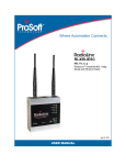
1
RLXIB-IHN-W
802.11n
Weatherproof Industrial Hotspot
October 1, 2010
SETUP GUIDE
Your Feedback Please
We always want you to feel that you made the right decision to use our products. If you have suggestions, comments,
compliments or complaints about our products, documentation, or support, please write or call us.
How to Contact Us
ProSoft Technology
5201 Truxtun Ave., 3rd Floor
Bakersfield, CA 93309
+1 (661) 716-5100
+1 (661) 716-5101 (Fax)
www.prosoft-technology.com
[email protected]
Copyright © 2010 ProSoft Technology, Inc., all rights reserved.
RLXIB-IHN-W Setup Guide
October 1, 2010
®
®
®
®
®
ProSoft Technology , ProLinx , inRAx , ProTalk , and RadioLinx are Registered Trademarks of ProSoft
Technology, Inc. All other brand or product names are or may be trademarks of, and are used to identify products
and services of, their respective owners.
ProSoft Technology® Product Documentation
In an effort to conserve paper, ProSoft Technology no longer includes printed manuals with our product shipments.
User Manuals, Datasheets, Sample Ladder Files, and Configuration Files are provided on the enclosed CD-ROM,
and are available at no charge from our web site: www.prosoft-technology.com
Printed documentation is available for purchase. Contact ProSoft Technology for pricing and availability.
North America: +1.661.716.5100
Asia Pacific: +603.7724.2080
Europe, Middle East, Africa: +33 (0) 5.3436.87.20
Latin America: +1.281.298.9109
Important Safety Information
The following Information and warnings pertaining to the radio module must be heeded:
WARNING – EXPLOSION HAZARD – DO NOT REPLACE ANTENNAS UNLESS POWER HAS BEEN SWITCHED
OFF OR THE AREA IS KNOWN TO BE NON-HAZARDOUS.
"THIS DEVICE CONTAINS A TRANSMITTER MODULE, FCC ID: RYK-WMIA199NI. PLEASE SEE FCC ID LABEL
ON BACK OF DEVICE."
"THIS DEVICE USES AN INTERNAL COMPACT FLASH RADIO MODULE AS THE PRIMARY RADIO
COMPONENT. THE COMPACT FLASH RADIO MODULE DOES NOT HAVE AN FCC ID LABEL. THE COMPACT
FLASH RADIO MODULE HAS NO USER SERVICEABLE PARTS."
"THIS DEVICE COMPLIES WITH PART 15 OF THE FCC RULES. OPERATION IS SUBJECT TO THE FOLLOWING
TWO CONDITIONS: (1) THIS DEVICE MAY NOT CAUSE HARMFUL INTERFERENCE, AND (2) THIS DEVICE
MUST ACCEPT ANY INTERFERENCE RECEIVED, INCLUDING INTERFERENCE THAT MAY CAUSE
UNDESIRED OPERATION."
"CHANGES OR MODIFICATIONS NOT EXPRESSLY APPROVED BY THE PARTY RESPONSIBLE FOR
COMPLIANCE COULD VOID THE USER’s AUTHORITY TO OPERATE THE EQUIPMENT."
Industry Canada Requirements:
"THIS DEVICE HAS BEEN DESIGNED TO OPERATE WITH AN ANTENNA HAVING A MAXIMUM GAIN OF 24 dB.
AN ANTENNA HAVING A HIGHER GAIN IS STRICTLY PROHIBITED PER REGULATIONS OF INDUSTRY
CANADA. THE REQUIRED ANTENNA IMPEDANCE IS 50 OHMS."
"TO REDUCE POTENTIAL RADIO INTERFERENCE TO OTHER USERS, THE ANTENNA TYPE AND ITS GAIN
SHOULD BE CHOSEN SUCH THAT THE EQUIVALENT ISOTROPICALLY RADIATED POWER (EIRP) IS NOT
MORE THAN THAT REQUIRED FOR SUCCESSFUL COMMUNICATION."
"THE INSTALLER OF THIS RADIO EQUIPMENT MUST INSURE THAT THE ANTENNA IS LOCATED OR
POINTED SUCH THAT IT DOES NOT EMIT RF FIELD IN EXCESS OF HEALTH CANADA LIMITS FOR THE
GENERAL POPULATION; CONSULT SAFETY CODE 6, OBTAINABLE FROM HEALTH CANADA."
Recommended Antennas
A2503S3-O
A2503S6-O
A5017NJ3-DP
A2408NJ-DP
A082503-80-OBH
A0524NJ-DP
Other Antennas with similar specifications may be substituted.
Antenna spacing requirements for user safety
It is important to keep the radio's antenna a safe distance from the user. To meet the requirements of FCC part
2.1091 for radio frequency radiation exposure, this radio must be used in such a way as to guarantee at least 20 cm
between the antenna and users. Greater distances are required for high-gain antennas. The FCC requires a
minimum distance of 1 mW *cm2 power density from the user (or 20 cm, whichever is greater).
If a specific application requires proximity of less than 20 cm, the application must be approved through the FCC for
compliance to part 2.1093.
Outdoor Radio Lightning Protection Grounding Instructions
The radio is to be installed by trained personnel or licensed electrician only and installation must
be carried out in accordance with the instructions listed here:
1 Each of the six active antennas MUST have a secure ground strap tied from the lightning
protector to a secured earth ground.
2 The power supply used in the testing of the radio was not evaluated and must be located in
an area known to be a non- hazardous location.
3 The power supply used for this testing is a Limited Power Source, “LPS”, having an output
voltage rating of 48 Volts direct current (Vdc) and an output current rating of 0.35 Amp (A).
4 Provisions for appropriately sized earthing and grounding shall be provided in the end-use
application.
5 Only lightning protectors approved by a Nationally Recognized Testing Laboratory (NRTL)
should be used in this installation.
6 The wire gauge used for earth grounding to the lightning protector must be in accordance
with the manufacturer’s instructions.
7 Outdoor field wiring must be in accordance with the National Electrical Code (NEC) and the
local jurisdiction.
Agency Approvals and Certifications
Wireless Approvals
Visit our web site at www.prosoft-technology.com for current wireless approval information.
Hazardous Locations
ANSI/ISA
12.12.01 Groups A, B, C, D
UL/cUL
C22.2 No. 213-M1987
ATEX
EN60079-0 and EN60079-15
Ordinary Locations
CSA/CB
EN60950 N. America & W. Europe
FCC/IC
Part 15, Class A and ICES-003
ETSI
ETSI EN300 328 and ETSI EN301 893
CSA C22.2 213-M1987 and N. American Standard ANSI/ISA 12.12.01 listing
In accordance with Canadian Standard CSA C22.2 213-M1987 and ANSI Standard ISA 12.12.01, the RLXIB series
radios have been UL listed for operation in Class I, Division 2, Groups A, B, C, and D Locations.
THIS EQUIPMENT IS SUITABLE FOR USE IN CLASS I, DIVISION 2, GROUPS A, B, C, AND D, HAZARDOUS
LOCATIONS AND IS POWERED BY A CLASS 2 ”Limited Power Source” (LPS) POWER SUPPLY.
WARNING: EXPLOSION HAZARD! SUBSTITUTION OF ANY COMPONENTS MAY IMPAIR SUITABILITY FOR
CLASS I, DIVISION 2.
WARNING – EXPLOSION HAZARD – Do not disconnect equipment unless power has been removed or the area is
known to be non-hazardous.
AVERRTISSEMENT - RISQUE D'EXPLOSION - LA SUBSTITUTION DE COMPOSANTS PEUT RENDRE CE
MATERIEL INACCEPTABLE POUR LES EMPLACEMENTS DE CLASSE I, DIVISION 2.
WARNING: EXPLOSION HAZARD! DO NOT DISCONNECT EQUIPMENT UNLESS POWER HAS BEEN
SWITCHED OFF OR THE AREA IS KNOWN TO BE NON HAZARDOUS.
AVERRTISSEMENT - RISQUE D'EXPLOSION - AVANT DE DECONNECTER L'EQUIPEMENT, COUPER LE
COURANT OU S'ASSURER QUE L'EMPLACEMENT EST DESIGNE NON DANGERUEX.
This radio has been designed to operate with the Omnidirectional Multi-Band Articulating Antenna, model A2502SOA and having a maximum gain of 3 dBi @ 2.4 GHz and 4 dBi @ 5.0 GHz. Antennas not listed herein having a gain
greater than that listed are strictly prohibited. The required antenna impedance is 50ohms nominal. This statement is
in accordance with RSS-Gen Section 7.1.4.
The following label is applied to the radio to indicate that it is listed under ANSI/ISA standard 12.12.01 and CSA
standard C22.2 213-M1987.
This Device contains a Radio Transmitter Module
FCC ID:RYK-WMIA199NI Canada IC: 5265A-IHN
Conforms to ANSI/ISA Std. 12.12.01 – Certified to CSA Std. C22.2 No. 213-M1987
Class I Division 2 10-24 Volts dc 13 Watts
48 Volts dc using the PoE Injector
Groups A, B, C & D
Max. Ambient: 60ºC
ATEX Approval
II 3 G
Ex nA nL IIC X
-30° C <= Ta <= 60° C
ProSoft Technology, Inc., Bakersfield, CA USA
Model: RLXIB
S/N: XXXXXXXXXX
Caution: Read instructions before operating in Hazardous Areas
Explosive Atmosphere
Power, Input, and Output (I/O) wiring must be in accordance with the authority having jurisdiction
A Warning – Explosion Hazard – Do not make or break connections in an explosive atmosphere.
B Caution – Use only approved recommended power supply.
C Warning - Power supply should be installed in a non-hazardous area.
D Warning – DO NOT OPEN WHEN ENERGIZED.
E The devices shall provide external means to prevent the rated voltage being exceeded by transient disturbances
of more than 40%. This device must be used only with ATEX certified backplanes.
United States FCC & Industry Canada rules
RYK-WMIA199NI
5265A-IHN
Note: This equipment has been tested and found to comply with the limits for a Class A digital device, pursuant to
Part 15 of the FCC Rules. These limits are designed to provide reasonable protection against harmful interference
when the equipment is operated in a commercial environment. This equipment generates, uses, and can radiate
radio frequency energy and, if not installed and used in accordance with the instruction manual, may cause harmful
interference to radio communications. Operation of this equipment in a residential area is likely to cause harmful
interference in which case the user will be required to correct the interference at his own expense.
This device complies with Part 15 of the FCC Rules. Operation is subject to the following two conditions: The device
may not cause harmful interference, and it must accept any interference received, including interference that may
cause undesired operation.
This Class A digital apparatus complies with Canadian ICES-003.
Cet appareil numérique de la classe A est conforme à la norme NMB-003 du Canada.
CAUTION: Changes or modifications not expressly approved by the manufacturer could void the user’s authority to
operate the equipment.
European CE certification
The radio modem has been approved for operation under the RTT&E directive, passing the following tests: ETS300826 (EMC), ETS300-328 (Functionality), and EN60950 (Safety).
The following is the appropriate label that is applied to the radio modem product line to indicate the unit is approved
to operate with CE certification:
The following is the appropriate label that is applied to the radio modem product line shipping package to indicate the
unit is approved to operate with CE certification:
AUS
B
DK
FIN
F
D
GR
IRE
I
LUX
NL
P
E
S
UK
Note: Member states in the EU with restrictive use for this device are crossed out. This device is also authorized for
use in all EFTA member states (CH, ICE, LI, and NOR).
EU Requirements
1. For outdoor use, France has a frequency restriction of 2.4 GHz to 2.454 GHz for an output power greater than 10
mW and below 100 mW.
2. For outdoor use in France, the output power is restricted to 10 mW in the frequency range of 2.454 GHz to 2.4835
GHz.
3. 5.15 GHz to 5.35 GHz is restricted to 200 mW EIRP throughout the European Union.
Power Supply and Accessories Warning
The certifications listed in this document apply to only the radio mentioned herein. These certifications do not extend
to any other items, including accessories or any external means of supplying power to the radio. Accessories and
power supplies shipped with the radio have not been tested and are not covered by these certifications. Any noncertified items added to the radio, including any means of supplying power, must be located in an area known to be
non-hazardous. All wiring to and from the Power-over-Ethernet (PoE) injector supplied with the radio must be routed
and installed inside the building or plant and never routed or installed outside of the building or plant.
Location and Use
The Industrial HotSpot radios, such as the RLXIB-IHN-W are used by professionals in Industrial
Applications/installations only and not used by the general consumer. These industrial radios
are used for industrial applications such as, water treatment facilities, power plants, factories,
railroads, remote oil/gas pipelines, refineries, cargo ships, refueling ships etc….and used for
wireless high speed data transmission. All radios are installed and used by professionals in
restricted areas.
RLXIB-IHN-W ♦ 802.11n
Weatherproof Industrial Hotspot
Contents
Setup Guide
Contents
Your Feedback Please ........................................................................................................................ 2
How to Contact Us .............................................................................................................................. 2
®
ProSoft Technology Product Documentation .................................................................................... 2
Important Safety Information............................................................................................................... 3
Antenna spacing requirements for user safety ................................................................................... 3
Outdoor Radio Lightning Protection Grounding Instructions .............................................................. 4
Agency Approvals and Certifications .................................................................................................. 5
CSA C22.2 213-M1987 and N. American Standard ANSI/ISA 12.12.01 listing ................................. 5
ATEX Approval.................................................................................................................................... 6
United States FCC & Industry Canada rules ...................................................................................... 6
European CE certification ................................................................................................................... 7
EU Requirements ................................................................................................................................ 7
Power Supply and Accessories Warning ............................................................................................ 7
1.1
Location and Use ...................................................................................................... 7
2
Before You Begin
2.1
2.2
2.3
2.4
2.5
2.6
2.7
11
Install the WirelessN Discovery Tool ....................................................................... 12
Start WirelessN Discovery Tool .............................................................................. 13
Plug In the Cables ................................................................................................... 14
Detecting the Radio ................................................................................................. 15
Assign an IP Address .............................................................................................. 16
Set Up a Repeater................................................................................................... 17
Save the Radio Configuration ................................................................................. 20
3
Adding and Configuring Additional Radios
21
4
Verify Communication
23
5
If You Encounter Problems
25
5.1
5.2
5.3
5.4
6
Check the Ethernet cable ........................................................................................ 26
LED display ............................................................................................................. 27
Retrieve the Default Password ................................................................................ 28
Starting Over ........................................................................................................... 29
What’s Next?
ProSoft Technology, Inc.
October 1, 2010
30
Page 9 of 30
Contents
Setup Guide
Page 10 of 30
RLXIB-IHN-W ♦ 802.11n
Weatherproof Industrial Hotspot
ProSoft Technology, Inc.
October 1, 2010
RLXIB-IHN-W ♦ 802.11n
Weatherproof Industrial Hotspot
1
Before You Begin
Setup Guide
Before You Begin
In This Chapter
Install the WirelessN Discovery Tool ..................................................... 12
Start WirelessN Discovery Tool ............................................................. 13
Plug In the Cables ................................................................................. 14
Detecting the Radio ............................................................................... 15
Assign an IP Address ............................................................................ 16
Set Up a Repeater................................................................................. 17
Save the Radio Configuration................................................................ 20
The following components are included with your RLXIB-IHN-W radio, and are all
required for installation and configuration.
Important: Before beginning the installation, please verify that all of the following items are
present.
Qty.
1
1
1
Part Name
RLXIB-IHN-W Radio
Cable
Cable
Part Number
RLXIB-IHN-W
RL-CBL025
RL-CBL029
Part Description
Weatherproof Industrial Hotspot
5 foot Ethernet Straight-Thru Cable (Gray)
5 foot RJ45 to M12 Straight Ethernet
1
Power-Over-Ethernet
Power Injector
POE-48i
RLX Power Injector, Input: 90 to 264 VAC,
Output: 0.35 A max @ 48 VDC.
1
ProSoft Solutions CD
Contains sample programs, utilities and
documentation for the RLXIB-IHN-W
module.
f any of these components are missing, please contact ProSoft Technology
Support for replacement parts.
In addition, you will need:
A personal computer equipped with an Ethernet port
IP address, Subnet Mask and Gateway information for each RLX device you
plan to install. You can obtain this information from your system
administrator.
Note: This Startup Guide is designed for use with two RLXIB-IHN-W radios. One radio will be
setup as a Master (AP) while the other radio will be set up as a Repeater.
ProSoft Technology, Inc.
October 1, 2010
Page 11 of 30
Before You Begin
Setup Guide
1.1
RLXIB-IHN-W ♦ 802.11n
Weatherproof Industrial Hotspot
Install the WirelessN Discovery Tool
1
Insert the ProSoft Solutions CD in your CD-ROM drive. On most computers,
a menu screen will open automatically. If you do not see a menu within a few
seconds, follow these steps:
a Click the Start button, and then choose Run.
b In the Run dialog box, click the Browse button.
c In the Browse dialog box, click "My Computer". In the list of drives,
choose the CD-ROM drive where you inserted the ProSoft Solutions CD.
d Select the file prosoft.exe, and then click Open.
e On the Run dialog box, click OK.
2 On the CD-ROM menu, select WIRELESSN DISCOVERY TOOL. This action
opens the Setup Wizard for WirelessN Discovery Tool.
3 Follow the instructions on the installation wizard to install the program with its
default location and settings.
4 When the installation finishes, you may be prompted to restart your computer
if certain files were in use during installation. The updated files will be
installed during the restart process.
Page 12 of 30
ProSoft Technology, Inc.
October 1, 2010
RLXIB-IHN-W ♦ 802.11n
Weatherproof Industrial Hotspot
1.2
Before You Begin
Setup Guide
Start WirelessN Discovery Tool
1
Click the START button, and then navigate to PROGRAMS / PROSOFT
TECHNOLOGY
2
Click to start RADIOLINX WIRELESSN DISCOVERY TOOL.
The window lists all the radios your computer can access. The MAC ID number is
essentially the serial number of the radio; this number is also printed on the side
of the radio. If a radio listing does not appear in the window, click the SCAN
button. If you still do not see a radio listing, see Troubleshooting in the RLXIBIHN-W User Manual.
ProSoft Technology, Inc.
October 1, 2010
Page 13 of 30
Before You Begin
Setup Guide
1.3
RLXIB-IHN-W ♦ 802.11n
Weatherproof Industrial Hotspot
Plug In the Cables
You can configure the RLXIB-IHN-W using the Ethernet port on the underside of
the radio. Use the Ethernet cable to configure the radio for the first time. Typical
configuration will also include providing power to the radio using the Power over
Ethernet (PoE) power injector included with the radio. Using this option
eliminates the need to run a separate power-only cable to the radio.
Note: The RLXIB-IHN-W radio receives both power and connectivity from the Ethernet cablecan
be powered using PoE by connecting the included M12 to RJ45 cable to the power injector and
inserting it into the Ethernet port. It can also be powered by connecting a separate 10-24VDC
source to the Power port.
Connections on the bottom of the radio, from left to right are:
o Power (not used when PoE option is used)
o Ethernet (with PoE option)
Note: After you plug in the Power over Ethernet (PoE) cable, the radio performs a startup
procedure that includes a self-test, loading the main program, and initializing the radio. The front
panel LEDs will illuminate after approximately two seconds. The entire startup procedure can take
up to 30 seconds.
After the startup procedure has completed successfully, the Power LED should
be GREEN, meaning that the radio has power. The Ethernet LED should also be
GREEN, meaning that the Ethernet connection is working. The RF Transmit and
RF Receive LEDs should blink.
For information on making connections, see Radio Power Requirements and
Cable Specifications in the RLXIB-IHN-W User Manual.
Page 14 of 30
ProSoft Technology, Inc.
October 1, 2010
RLXIB-IHN-W ♦ 802.11n
Weatherproof Industrial Hotspot
1.4
Before You Begin
Setup Guide
Detecting the Radio
After the radio has completed its startup procedure, the radio will appear in the
WirelessN Discovery Tool window.
The window lists all the radios your computer can access. The MAC ID number is
essentially the serial number of the radio; this number is also printed on the side
of the radio. If a radio listing does not appear in the window, click the SCAN
button on the toolbar. If you still do not see a radio listing, refer to Diagnostics
and Troubleshooting in the RLXIB-IHN-W User Manual.
ProSoft Technology, Inc.
October 1, 2010
Page 15 of 30
Before You Begin
Setup Guide
1.5
RLXIB-IHN-W ♦ 802.11n
Weatherproof Industrial Hotspot
Assign an IP Address
You need the IP address to log into the RadioLinx Configuration Manager and
configure the radio settings. If the radio is connected to a network with a DHCP
server, the radio may already have an IP address assigned to it.
If a DHCP server is not available, or if you prefer to assign a static IP address,
you can enter an IP address here.
To assign an IP Address
1
In WirelessN Discovery Tool, click to select the radio.
Tip: If a radio listing does not appear in the window, click the Scan button on the toolbar. If you still
do not see a radio listing, refer to Diagnostics and troubleshooting in the RLXIB-IHN-W User
Manual.
2
Right-click on the radio to open a shortcut menu, and then choose ASSIGN IP.
This action opens the Assign IP Address dialog box.
3
Select one of the unused IP addresses, and then click OK.
Tip: You must also assign a Gateway address. The Gateway assigned to your PC’s Ethernet port
is offered as a suggestion. If your PC does not have a Gateway setting, the Gateway field in the
Assign IP Address dialog will be blank. You will need to enter a Gateway before clicking OK.
For information, see Radio Access settings in the RLXIB-IHN-W User Manual.
Page 16 of 30
ProSoft Technology, Inc.
October 1, 2010
RLXIB-IHN-W ♦ 802.11n
Weatherproof Industrial Hotspot
1.6
Before You Begin
Setup Guide
Set Up a Repeater
To configure the radio, double click on the radio (Radio1) in the WirelessN
Discovery Tool window. This action opens a web browser (for example Microsoft
Internet Explorer or Firefox) and loads the Radio’s web configuration interface.
Administrator login
With administrative privileges, you can view or modify the configuration of the
access point.
Enter the user name in lower case, no quotes.
The default administrator user name is "admin"
The default password is "password"
The user name and password are case sensitive
Guest login
With guest privileges, you can view the existing configuration, but you cannot
make changes.
Enter the user name in lower case, no quotes.
The default guest user name is "guest".
The default password is "password".
Important: You should change the default user names and passwords, write down the settings,
and keep a copy in a safe place, to protect the radio from being reconfigured or viewed by
unauthorized users.
Note: The master is the "root" or central radio in a network. You must have at least one master
radio per network. For redundancy, you can assign more than one master to a network.
ProSoft Technology, Inc.
October 1, 2010
Page 17 of 30
Before You Begin
Setup Guide
RLXIB-IHN-W ♦ 802.11n
Weatherproof Industrial Hotspot
To configure Radio 1 as a Repeater, make the following changes to the web
configuration form:
Page 18 of 30
ProSoft Technology, Inc.
October 1, 2010
RLXIB-IHN-W ♦ 802.11n
Weatherproof Industrial Hotspot
Before You Begin
Setup Guide
Radio Network Settings
Unit Name: Enter a unique name for the radio.
Obtain IP Address by: If a DHCP (Dynamic Host Control Protocol) server is
configured on your local area network, the DHCP server can assign IP
addresses automatically.
If you prefer to assign a Static (Fixed) IP address, select STATIC, and then
enter the IP Address, Subnet Mask and Default Gateway in the Overall area
of the Radio web configuration form.
Important: If you intend to assign IP addresses manually, you must not duplicate an IP address
that is already in use on your network. If you are not sure what IP addresses are available, ask
your network administrator for assistance.
Select REPEATER as the radio mode.
SSID: Enter the SSID you configured for the Master radio. All radios in a
network must have the same SSID.
Security: Encryption scrambles data so that only intended viewers can
decipher and understand it. Choose the same encryption type you configured
for the Master radio.
WPA/WPA2 Key: Enter the pass phrase you configured for the Master radio.
Important: The Network SSID and WPA phrase are case sensitive. Use exactly the same
combination of upper case and lower case letters you entered for the Master radio, otherwise the
Repeater radio will not be able to connect to the Master radio.
By default, a repeater connects automatically to the best available parent radio
on the network. If necessary, however, you can click the Parent Link button and
specify how repeater radios connect to the network. See Parent Link settings in
the RLXIB-IHN-W User Manual for information.
ProSoft Technology, Inc.
October 1, 2010
Page 19 of 30
Before You Begin
Setup Guide
1.7
RLXIB-IHN-W ♦ 802.11n
Weatherproof Industrial Hotspot
Save the Radio Configuration
Before browsing to other pages in the Radio Configuration window, you must
apply your changes. Click APPLY to save your configuration and restart the radio.
Note: To discard your changes and start over, click CLEAR.
Page 20 of 30
ProSoft Technology, Inc.
October 1, 2010
RLXIB-IHN-W ♦ 802.11n
Weatherproof Industrial Hotspot
2
Adding and Configuring Additional Radios
Setup Guide
Adding and Configuring Additional Radios
At this point you should attach and configure any additional radios you will be
using. Ensure that any new radios use a unique name, but the same Network
SSID as your master. The only difference in procedure will be in setting up each
additional radio. Instead of setting your additional radios as Masters, they should
be set as Repeaters or, more rarely, Clients, depending on their intended
purpose.
ProSoft Technology, Inc.
October 1, 2010
Page 21 of 30
Adding and Configuring Additional Radios
Setup Guide
Page 22 of 30
RLXIB-IHN-W ♦ 802.11n
Weatherproof Industrial Hotspot
ProSoft Technology, Inc.
October 1, 2010
RLXIB-IHN-W ♦ 802.11n
Weatherproof Industrial Hotspot
3
Verify Communication
Setup Guide
Verify Communication
When configured, the Roles column identifies each radio as a Master, Repeater,
or Client.
Observe the LEDs to ensure good link quality, as explained in LED display (page
27).
ProSoft Technology, Inc.
October 1, 2010
Page 23 of 30
Verify Communication
Setup Guide
Page 24 of 30
RLXIB-IHN-W ♦ 802.11n
Weatherproof Industrial Hotspot
ProSoft Technology, Inc.
October 1, 2010
RLXIB-IHN-W ♦ 802.11n
Weatherproof Industrial Hotspot
4
If You Encounter Problems
Setup Guide
If You Encounter Problems
In This Chapter
Check the Ethernet cable ...................................................................... 26
LED display ........................................................................................... 27
Retrieve the Default Password .............................................................. 28
Starting Over ......................................................................................... 29
ProSoft Technology, Inc.
October 1, 2010
Page 25 of 30
If You Encounter Problems
Setup Guide
4.1
RLXIB-IHN-W ♦ 802.11n
Weatherproof Industrial Hotspot
Check the Ethernet cable
If you connect a radio and the Ethernet LED does not light on the radio, there
may be a problem with the Ethernet cable. Verify that the cable is plugged into
the radio at one end, and to an Ethernet hub or a 10/100 Base-T Ethernet switch
at the other end. If using the PoE injector, verify that the M12 to RJ45 cable is
connected between the radio and the injector and also that the Ethernet patch
cable is connected between the injector and switch.
Note: The RLXIB-IHN-W radio auto-detects the Ethernet connection type, and does not require a
crossover cable for direct connection to a PC.
Page 26 of 30
ProSoft Technology, Inc.
October 1, 2010
RLXIB-IHN-W ♦ 802.11n
Weatherproof Industrial Hotspot
4.2
If You Encounter Problems
Setup Guide
LED display
The RLXIB-IHN-W front panel includes a set of LEDs that indicate the radio’s
status:
LED
Description
Power
This green LED indicates that the radio has power.
RF Transmit
This yellow LED indicates RF transmission.
RF Receive
This green LED indicates RF reception.
Net & Mod
Reserved for future use.
Ethernet
If this green LED is on, the Ethernet cable is connected. If this LED is flashing,
an Ethernet packet is being transmitted or received.
Signal Strength
If only one of these three LEDs is on, then the radio is linked. If two LEDs are on,
the radio’s signal strength is fair. If all three LEDs are on, the signal strength is
good.
If a radio is configured as a master, the middle light of the three Signal Strength
LEDs will always be on, and the bottom Signal Strength LED will always be off.
The top LED on the master will flash if any radios are linked to this master.
After you first plug in the power cable and Ethernet cable to the radio, the
Power/Status LED should be green, meaning that the radio has power. If the
Ethernet LED is green, then the Ethernet connection is working. The RF Transmit
and RF Receive LEDs should blink.
All three LEDs will blink just after the radio links to the Master’s signal but before
it has been fully authenticated. Normally you will see this last only a few seconds.
If it blinks longer, or never turns on, it usually means the encryption keys are not
correct.
ProSoft Technology, Inc.
October 1, 2010
Page 27 of 30
If You Encounter Problems
Setup Guide
4.3
RLXIB-IHN-W ♦ 802.11n
Weatherproof Industrial Hotspot
Retrieve the Default Password
If you forget your password, you will be unable to change the radio settings. You
can retrieve the default password to use the software again, but you will lose all
the settings you programmed before. To retrieve the default password and return
the radio to its default settings, follow these steps:
1 Turn OFF power to the radio.
2 Feel for the reset button, located under the red "diamond" on the face of the
radio.
3
4
Turn ON power to the radio, and wait for the Power LED to turn green.
When the Power LED turns green, press and hold the reset button for at least
five seconds.
5 The radio will reload its default settings, including the PASSWORD. You should
now be able to log in using the default USERNAME and PASSWORD.
o The default administrator USERNAME is "admin"
o The default PASSWORD is "password"
o The USERNAME and PASSWORD are case sensitive
Page 28 of 30
ProSoft Technology, Inc.
October 1, 2010
RLXIB-IHN-W ♦ 802.11n
Weatherproof Industrial Hotspot
4.4
If You Encounter Problems
Setup Guide
Starting Over
If necessary, you can always restore the default settings that were present when
the radio was manufactured.
1 Open the Radio Configuration/Diagnostic Utility
2 Log into the radio
3 Click the Utilities button, and then click the Default button.
This will remove all changes you have made to the radio configuration,
including addressing, naming, and security settings.
ProSoft Technology, Inc.
October 1, 2010
Page 29 of 30
What’s Next?
Setup Guide
5
RLXIB-IHN-W ♦ 802.11n
Weatherproof Industrial Hotspot
What’s Next?
Congratulations! Your wireless network is up and running. You now need to
connect your wireless Hotspots to your network devices. ProSoft Technology
provides application connection instructions for numerous applications. Refer to
the RadioLinx Application Connection Guide located on the RadioLinx Solutions
CD.
Page 30 of 30
ProSoft Technology, Inc.
October 1, 2010