1
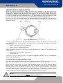
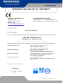
© 2010 – 2012 Datalogic Automation S.r.l. - ALL RIGHTS RESERVED - Protected to
the fullest extent under U.S. and international laws. • Copying, or altering of this
document is prohibited without express written consent from Datalogic Automation
S.r.l.
Datalogic and the Datalogic logo are registered trademarks of Datalogic S.p.A. in
many countries, including the U.S.A. and the E.U.
All other brand and product names mentioned herein are for identification purposes
only and may be trademarks or registered trademarks of their respective owners.
Published 06 November 2012
Printed in Donnas (AO), Italy.
EOX 10W – User’s Manual
ii
SYMBOLS
SYMBOLS
The symbols used in this manual along with their meaning are shown below. The symbols are repeated
within the chapters and/or sections and have the following meaning:
Generic warning:
This symbol indicates the need to read the manual carefully or the necessity of an important
operation or maintenance.
Electricity warning:
This symbol indicates dangerous voltage associated with the laser, or powerful enough to constitute
an electrical risk. This symbol may also appear on the machine at the risk area.
Laser warning:
This symbol indicates the danger of exposure to visible or invisible laser radiation. This symbol may
also appear on the machine at the risk area.
Fire warning:
This symbol indicates the danger of a fire when processing flammable materials. Because there is a
danger of fire, it is indispensable to follow the instructions provided by the manufacturer when
commissioning the machine.
Note:
Refer to dedicated user’s manual.
iii
EOX 10W – User’s Manual
REVISION INDEX
REVISION INDEX
Revision
Date
Number of added or
edited pages
0.0
20-10-2011
Release
821002150
10-02-2012
Appendix A
821002151
05-09-2012
30
821002152
07-11-2012
19, 38, 41, 43
EOX 10W – User’s Manual
iv
FOREWORD
FOREWORD
The information contained in this manual is intended for a qualified installer capable of integrating
the machine into a system, completing it with all protection systems required by international
standards and local laws.
The following manual refers to the Eox 10W model, in CLASS 4 LASER configuration.
In addition to being professionally trained in their role, personnel assigned to work on the machine must be
informed and made acquainted with the risks inherent invisible and visible laser radiation. The operator is
required to carefully read the section of the manual concerning safety instructions as well as the sections
related to matters falling under his responsibility.
The workers assigned to the machine can be identified as:
•
OPERATOR
responsible for loading elements to be processed, visually checking the work cycle, removing the
finished product and cleaning the machine.
•
MAINTENANCE WORKER
responsible for the electrical, mechanical and optical maintenance and adjustment of the machine.
NOTE:
Datalogic Automation S.r.l. declines any and all responsibility for improper use of its device.
NOTE:
BEFORE INSTALLING AND USING THE LASER, READ CAREFULLY THE APPENDICES.
v
EOX 10W – User’s Manual
OVERVIEW
OVERVIEW
The CO2 Eox 10W laser marking system developed and manufactured by Datalogic Automation employs the
most advanced technologies with regards to the mechanical-optical part, the electronic control of laser beam
power, communication and the overall safety of the entire system.
OPERATION OF A LASER SYSTEM WITH GALVANOMETRIC SCANNING
In pulsed or continuous operation mode, the CO2 generates an invisible, high-energy infrared beam.
In order to obtain a more accurate focus, the laser beam is first enlarged by using an optical expansion
system and then focused, after being deflected by a scanning system consisting of two mirrors mounted on
galvanometric motors.
These mirrors deflect the beam in a controlled fashion along the X and Y axes; etching of the product
surface occurs by coordinating the movement of the two motors with the turning on/off of the laser beam.
The deflected laser beam is focused by an F-Theta lens before it hits the surface of the product.
Generally speaking, the marking is carried out within the focus of the beam.
LASER SOURCE
A sealed gas laser tube is used in the Eox 10W system.
The tube contains a gas mixture (usually CO2, N2 and He) which is excited by a radiofrequency generator to
bring it to a plasma state.
The produced radiations are reflected back and forth between the mirrors, which represent the “resonant
laser cavity”; the laser beam is amplified with each reflection.
While one of the two mirrors (rear) is 100% reflectant, the output mirror (front) reflects only 95%; this slight
loss of 5% represents the laser radiation used for etching purposes.
GALVANOMETRIC SCANNING HEAD
The scanning head features two deflection mirrors that deflect the beam in an X and Y direction, depending
on the graphics to be reproduced.
NOTE:
Device installation in secure environment is responsibility of the system integrator!
EOX 10W – User’s Manual
vi
OVERVIEW
The Eox 10W laser system is composed by a single device (All-In-One) with laser head and compact
dimensions for an easy integration inside a complex system able to manage marking signals and customer’s
complementary modules.
All laser system connections are found on the back of device: supply input, controls and signals and
interfaces for internal embedded controller. Moreover is available an inlet air to use to maintain clean the
marking area thanks to holes around the focal lens.
Two side cooling belts are provided for cooling down the laser; their flow must never be obstructed.
Figure 1: Eox 10W.
vii
EOX 10W – User’s Manual
OVERVIEW
INTENDED USE
The Eox 10W source is intended for the identification marking of organic and plastic materials and for the
removal of coatings, paints and surface treatments from metals.
NOTE:
CO2 marking systems mainly interact with materials through a thermal carbonization process with
the emission of fumes and vapours.
Suitable methods for the treatment and abatement of marking fumes must be provided for,
especially when working on plastic materials.
IMPORTANT WARNINGS
Access to the internal parts of the electrical equipment is allowed only to authorized personnel, duly qualified
and trained with regards to risks of an electrical nature.
Datalogic Automation S.r.l. declines any and all responsibility for work carried out on live parts by untrained
or unauthorized personnel.
NOTE:
It is forbidden to change the intended use for which the system was designed and developed.
Datalogic Automation S.r.l. declines any and all responsibility for improper use of its equipment.
EOX 10W – User’s Manual
viii
OVERVIEW
ix
EOX 10W – User’s Manual
SUMMARY
SUMMARY
SYMBOLS
III
REVISION INDEX
IV
FOREWORD
V
OVERVIEW
VI
OPERATION OF A LASER SYSTEM WITH GALVANOMETRIC SCANNING
LASER SOURCE
GALVANOMETRIC SCANNING HEAD
INTENDED USE
IMPORTANT WARNINGS
SUMMARY
1
X
TECHNICAL SPECIFICATIONS AND ACCESSORIES
12
1.1
TECHNICAL CHARACTERISTICS
1.2
SEALS
1.3
CONTENTS OF THE PACKAGING
1.3.1
FOCAL OBJECTIVES (F-Theta)
2
12
14
15
16
INSTALLATION AND SET UP
18
2.1
UNITS DESCRIPTION
2.2
INSTALLATION PRE-REQUISITES
2.3
EOX TRANSPORT
2.4
FIXING AND POSITIONING
2.5
INSTALLATION ENVIRONMENT
2.6
WIRING
2.6.1
CONNECTION COMMAND BOX CONNECTOR
2.6.2
INTERLOCK CONNECTION
2.6.3
POWER SUPPLY CONNECTION
2.6.4
LOCAL CONTROL MODE CONNECTION
2.6.5
REMOTE CONTROL MODE CONNECTION
2.6.6
AXES CONNECTION (I/O CONTROL)
2.6.7
MARKING ON FLY MODE CONNECTION
2.7
SOFTWARE UPGRADE
3
18
19
20
21
22
23
23
23
24
25
26
27
28
30
USE AND OPERATION
3.1
vi
vi
vi
viii
viii
34
POWER ON PROCEDURE
34
EOX 10W – User’s Manual
x
SUMMARY
4
TECHNICAL SPECIFICATION
4.1
EXTERNAL CONNECTORS SPECIFICATIONS
4.1.1
INTERLOCK – PANEL PLUG
4.1.2
INTERLOCK – MOVABLE SOCKET
4.1.3
ENCODER CONNECTOR
4.1.4
PHOTOCELL CONNECTOR
4.1.5
INPUT SIGNAL SPECIFICATIONS
4.1.6
COMMAND BOX CONNECTOR – PANEL SOCKET
4.1.7
TIMING DIAGRAM COMMAND BOX LASER SIGNALS
4.1.8
AXES CONNECTOR (I/O CONTROL)
4.2
MAINTENANCE
APPENDIX A: LABEL IDENTIFICATION
POSITIONING OF EXTERNAL LABELS
APPENDIX B : STANDARDS
LASER STANDARDS
CE COMPLIANCE
FCC COMPLIANCE
38
38
38
38
39
39
40
41
43
46
47
48
49
50
50
50
50
APPENDX C : GUIDE FOR SYSTEM INTEGRATOR
51
APPENDIX D: NOTE ABOUT LASER
52
LASER SAFETY
LASER RADIATION
ABSORPTION OF LASER RADIATION
CLASSIFICATION AND DANGER LEVEL
RADIATION VIEWING CONDITIONS
DIRECT VIEWING OF THE LASER BEAM
DIRECT VIEWING OF THE BEAM AFTER MIRROR REFLECTION
DIRECT VIEWING OF THE BEAM AFTER FOCUSING
SCATTERED VIEWING OF THE BEAM AFTER FOCUSING
EYES AND SKIN RISKS
GENERAL SAFETY REGULATIONS
COLLATERAL RISKS
52
54
55
55
56
56
56
56
56
57
57
57
APPENDIX E: DECLARATION OF CONFORMITY
60
FIGURES
62
xi
EOX 10W – User’s Manual
CHAPTER 1
1 TECHNICAL SPECIFICATIONS AND ACCESSORIES
NOTE:
BEFORE INSTALLING AND USING THE LASER, READ CAREFULLY THE APPENDIXES.
1.1 TECHNICAL CHARACTERISTICS
RESONATOR MECHANICAL CHARACTERISTICS
Weight
17 Kg
Height
185 mm
Width
180 mm
Depth
634 mm
IP Degree
IP21
Figure 2: EOX 10W Resonator overall dimensions.
EOX 10W – User’s Manual
12
CHAPTER 1
SPECIFICATIONS
Laser Source
CLASS 4, CO2 sealed laser tube
Configuration
All-In-One
Scanning Head
Average Power
Straight, Left side, Right side
1
Stability
± 10% (cold start)
Wavelength
10.57-10.63 µm; Peak @10.6 µm
Range Frequency
10 – 25000 Hz; CW
Rise Time
< 150 µs
M2
≤ 1.2
Beam Ø1
~ 3.5 mm @ 1/e2
Standard Bexp
2x
Ellipticity
< 1.2
Divergence
1
< 4 mrad
Aiming Beam
2x Class 2M red Diode Laser; λ=635nm ± 5nm; 3mW (aiming and
focusing)
Marking Area
70x70 mm = [ƒ = 100mm]
140x140 mm = [ƒ = 200mm]
Marking Speed2
2000 mm/sec, 500 chr/sec
Spot Size3
270 µm [ƒ = 100mm]
370 µm [ƒ = 200mm]
Cooling
Integrated Fan-Cooled
Power Supply
100/240 VAC – 50/60Hz
Absorption
Typical 400W, Maximum 600W
Marking on the Fly (MOF)
MOF line speed
4
YES [constant speed or encoder]
Up to 75 m/min – 4 pieces/sec.
Temperature range
Operating: Min. +15 °C (59°F) / Max +35 °C (95°F)
Storage: Min. -10°C (-14°F) / Max. +60°C (140°F)
Humidity
0 – 95%, non-condensing
Standard version supplied
Inputs
Outputs
Interface
Options
1
2
13
10W
Mechanical shutter, I/O control signals Interfaces, 4-axes control
Interface, photocell and encoder ports, f-theta lens 100 nm, external
connectors and marking software
Remote and locals interlock, remote key, remote shutter control,
encoder, photocell, start marking, stop marking, pause marking, etc...
Marking ready, marking busy, marking complete, good/bad marking,
shutter open, alarm/error, etc…
2x USB 2.0, Ethernet LAN (TCP/IP), VGA, PS/2 keyboard, 4-axes
signals, Encoder and photocell, I/O signals and RS232 port
200mm F-Theta lens
Photocell
Measured @ resonator exit
May vary: measured with f= 200mm
EOX 10W – User’s Manual
3
4
With Bexp 2x on 10W
Single line string, Roman-s font
CHAPTER 1
1.2 SEALS
Several seals have been applied to the Eox 10W source:
Figure 3: Example of a seal.
The engraving system has seals in some areas. The seals must not be broken or removed for any reason.
The sealed parts may be opened only and exclusively by Datalogic Automation S.r.l. Breakage of these
seals by a customer shall result in immediate cancellation of the warranty on the entire engraving system.
NOTE:
If a customer breaks or removes the seals placed by the manufacturer on the laser system the
warranty on the entire laser system will immediately become null and void.
WARNING!
The manufacturer shall not be held liable for any non conforming use of equipment of its
manufacture.
It is forbidden to operate the equipment before the machine it is intended for has been declared in
conformance with statutory Directives.
NOTE:
Access to the internal parts of the electrical equipment is only permitted for authorized personnel,
who have been trained and instructed on the electrical risks!
Datalogic Automation S.r.l. shall not be held liable for work on electrically charged parts by
inadequately trained personnel!
NOTE:
Access to the internal parts of the resonator is only permitted for authorized personnel, who have
been trained and instructed on the optical risks!
Datalogic Automation S.r.l. shall not be held liable for work on parts by inadequately trained
personnel!
EOX 10W – User’s Manual
14
CHAPTER 1
1.3 CONTENTS OF THE PACKAGING
MAIN HARDWARE
Figure 4: Eox 10W.
CABLE AND ACCESSORIES
Figure 5: Command Box connector
15
EOX 10W – User’s Manual
Figure 6: Interlock
Figure 7: Power supply cable.
CHAPTER 1
1.3.1 FOCAL OBJECTIVES (F-Theta)
F-Theta Scanning Lenses are commonly used in laser marking, engraving, and cutting systems.
F-theta lenses are designed to provide a flat field at the image plane of the scanning system.Different FTheta lens models are available upon request to allow different marking areas and to find the best
compromise between marking field (or marking areas) and resolution of the marked string or logo, depending
on specific needs. These F-Theta lenses are compatible with the standard scanner head supplied by
Datalogic Automation; other solutions concerning both the scanner head and the lenses can be evaluated on
a case-by-case basis.
F-Theta 1070nm
Lens diameter (mm)
Working Distance (mm)
Fixing Distance (mm)
Marking Area (mm x mm)
100
48
100*
100*
70 x 70
200
48
200*
200*
140 x 140
* Tolerance: ± 2mm
Note: Working Distance is defined as the distance between the center of the working area (defined in
the focal plane) and the base of the resonator:
WD: Working Distance
FD: Fixing Distance
MA: Marking Area
EOX 10W – User’s Manual
16
CHAPTER 1
17
EOX 10W – User’s Manual
CHAPTER 2
2 INSTALLATION AND SET UP
NOTE:
Eox10 is a Class 4 laser source.
For proper use under conditions of safety they must be brought to Class 1.
Consequently, the Eox 10W laser device must be installed in a suitable environment specifically dedicated to
laser jobs.
The person in charge of the area assigned to laser marking (the Laser Safety Officer), has to isolate this area
from the other work areas and signal through suitable hazard warnings that the area assigned to laser
marking can be accessed by authorized personnel only.
See Appendix for more information.
2.1 UNITS DESCRIPTION
The device is described here below in order to provide the right information for proper device installation.
Figure 8: EOX 10W overview.
1) Main power supply
8) LAN
2) Command Box Plug Connector
9) VGA
3) Axes Plug Connector
10) PS/2 keyboard
4) Inlet air
11) Photocell connector
5) Interlock
12) Encoder connector
6) USB 2.0
13) Status Led bar
7) RS232
14) Focal with air compressed issue holes
EOX 10W – User’s Manual
18
CHAPTER 2
2.2 INSTALLATION PRE-REQUISITES
Once it is installed in a suitable environment, the Eox 10W marking system is already set for use since it is
equipped with an intelligent embedded controller.
If the system is not used in remote mode, a monitor and input peripheral devices (material not included) are
nevertheless needed. Once parameters setup on Eox 10W marking system it is possible to work without any
input peripheral device connected.
In order to have a normal functionality of the laser system it is necessary to prepare an external interface
that enables all the requested input.
NOTE:
See chapter 4 for more information.
Figure 9: External connections example.
19
EOX 10W – User’s Manual
CHAPTER 2
2.3 EOX TRANSPORT
The Eox 10W laser needs to be moved in order to proceed to its positioning and wiring. The Eox 10W device
can be easily lifted up and moved by a single person thanks to its compact size and reduced weight.
Figure 10: EOX transport.
NOTE:
The Eox 10W laser system is a delicate opto-electronic device, avoid damaging shock and
vibrations.
EOX 10W – User’s Manual
20
CHAPTER 2
2.4 FIXING AND POSITIONING
The Eox 10W marker must be safely positioned and must be followed below instructions.
The device must be secured to a suitable base (not supplied by Datalogic Automation S.r.l.) using the four
M6 threaded holes:
Figure 11: Fixing points on resonator (standard mount).
The Eox 10W device must be safely positioned and secured to a specific surface, parallel to the marking
area and totally vibration-free. The resonator can be fixed either vertically or horizontally. In order to prevent
marking distortions, fit a vibrometer at the base of the piece to be marked and make sure there are no
vibrations during the marking process. It is also possible to request a different position of the scanning head
in order to have a side laser output.
Figure 12: Fixing points on resonator (right angle side).
21
EOX 10W – User’s Manual
CHAPTER 2
Figure 13: Fixing points on resonator (left angle side).
2.5 INSTALLATION ENVIRONMENT
The Eox 10W device must be installed in a suitable environment in order to allow proper air flow passage
and correct housing of the cables:
Figure 14: Resonator installation environment.
EOX 10W – User’s Manual
22
CHAPTER 2
2.6 WIRING
The machine wiring is described here below. Follow the wiring operations as described.
WARNING:
Wire the devices one to the other WITH NO voltage in order to avoid risks to the operator and to the
laser source.
2.6.1 CONNECTION COMMAND BOX CONNECTOR
Connect Command Box connector on back panel. If this connection is not present the system can’t be used
because it goes in error status. Refers to chapter 4 for any further information on external connections.
Figure 15: Connection Command Box connector.
2.6.2 INTERLOCK CONNECTION
Wiring interlock connector. The absence of such connector shuts down the device.
Figure 16: Interlock connection.
23
EOX 10W – User’s Manual
CHAPTER 2
2.6.3 POWER SUPPLY CONNECTION
WARNING:
First of all, make sure the power supply is turned off, and consequently that there is no voltage in
the cables connecting power supply.
Wiring power supply cable (100÷240VAV 50÷60Hz).
Figure 17: Wiring power supply cable.
EOX 10W – User’s Manual
24
CHAPTER 2
2.6.4 LOCAL CONTROL MODE CONNECTION
To use the laser in “Local Control” mode is necessary to use an USB mouse, PS/2 keyboard and VGA
monitor. After setting up system parameters and marking project selection is possible to use the system
without input peripheral devices connected. If automatic mode is selected on the marking software it is
possible to work without help of operators. Connect VGA monitor and input devices as shown below:
Figure 18: USB mouse connection.
Figure 19: PS/2 keyboard connection.
NOTE:
It is also possible to connect input devices using the USB Connection.
25
EOX 10W – User’s Manual
CHAPTER 2
Figure 20: VGA monitor connection.
2.6.5 REMOTE CONTROL MODE CONNECTION
To use “Remote Control” mode it is necessary a LAN cable connection. This configuration permits to control
the system by an external PC in order to send from a remote position a marking project and check the laser
status.
Figure 21: Ethernet connection.
EOX 10W – User’s Manual
26
CHAPTER 2
2.6.6 AXES CONNECTION (I/O CONTROL)
In case of moving axes control it is possible to connect to a dedicated port (Refer to chapter 4 for any further
information).
Figura 22: Axes connector connection.
27
EOX 10W – User’s Manual
CHAPTER 2
2.6.7 MARKING ON FLY MODE CONNECTION
Dynamic state of marking is used for critical production where it is not possible to stop the marking objects.
To use the laser device in “Marking on fly” mode is necessary wiring a photocell sensor and an encoder (not
supplied by Datalogic Automation):
Figure 23: Photocell connection.
Figure 24: Encoder connection.
EOX 10W – User’s Manual
28
CHAPTER 2
CONNECTIONS EXAMPLE
NOTE:
It is important to install an emergency circuit able to cut input power supply (VAC) switching off
Eox entirely. This safety circuit needs to be installed from qualified personnel only.
29
EOX 10W – User’s Manual
CHAPTER 2
2.7 SOFTWARE UPGRADE
This document describe how to update SW version on Eox systems:
1. Close the Lighter and Laser Engine (Click on “QUIT”)
2. Do Lighter “UNISTALL”: you can’t run the new installer before having removed the old SW version.
EOX 10W – User’s Manual
30
CHAPTER 2
3. Attendere la fine della procedura di disinstallazione.
4. Eseguire il nuovo installer di Lighter da un dispositivo esterno (USB dongle).
5. Attendere la fine della procedura di installazione.
6. A seconda che l’aggiornamento di Lighter contenga o meno degli aggiornamenti per la scheda di
controllo, verrà visualizzata o meno la schermata sottostante:
•
Procedura con aggiornamento della scheda di controllo:
o
premere OK per eseguire l’aggiornamento della scheda di controllo
o
al termine della procedura verrà visualizzata la finestra che indica il salvataggio
automatico dei dati nel sistema
entro 10 secondi il sistema verrà arrestato in automatico
ATTENZIONE:
NON spegnere il dispositivo!
31
o
attendere lo shutdown automatico del sistema (schermata nera)
o
spegnere il sistema per completare l’installazione
EOX 10W – User’s Manual
CHAPTER 2
•
Procedura senza aggiornamento della scheda di controllo:
o
viene visualizzata la finestra che indica il salvataggio automatico dei dati nel sistema
o
entro 10 secondi il sistema verrà riavviato in automatico
ATTENZIONE:
NON spegnere il dispositivo!
o
attendere il riavvio automatico del sistema
EOX 10W – User’s Manual
32
CHAPTER 2
33
EOX 10W – User’s Manual
CHAPTER 3
3 USE AND OPERATION
3.1 POWER ON PROCEDURE
First to proceed with turn on the Eox 10W laser system, insure to a right device connection like
described previously.
NOTE:
First to use laser system must be read marking software user manual.
Proceed as follow:
1)
Provide power supply to the device by pressing the switch on the power input jack:
Figure 25: Power on.
If the system is turned on cooling fans are running. Through Command Box connector on back panel is
possible to check that the system is switched on by auxiliary 12VDC voltage available on the output pins.
EOX 10W – User’s Manual
34
CHAPTER 3
2)
After initialization procedure is done (warm up) the system allows to able “KEY” signal on Command
Box connector available of back panel:
Figure 26: KEY command activation.
With “KEY” signal activated led bar on the system comes green and “laser active” signal is enabled on
Command Box connector.
NOTE:
Refer to chapter 4 for any further information on the connections.
Figure 27: Status led display.
35
EOX 10W – User’s Manual
CHAPTER 3
3)
Now activate the “ENABLE” signal on the Command Box connector:
Figure 28: ENABLE command activation.
NOTE:
Refer to chapter 4 for any further information on the connections.
WARNING:
During this status, the shutter is opened and it is possible to have LASER beam output!
The system is ready to mark. The led bar status on device will turn orange. “SHUTTER_OPEN” signal
will activate on Command Box connector in the back panel.
Figure 29: Status led display.
EOX 10W – User’s Manual
36
CHAPTER 3
4)
To laser emission it is possible to operate manually through the marking software or in automatic mode
by external START signal. During the emission led bar will be red. “Busy” output signal will be active on
the Command Box connector in back panel.
Figure 30: Status led display.
NOTE:
Refer to chapter 4 for any further information on the connections.
37
EOX 10W – User’s Manual
CHAPTER 4
4 TECHNICAL SPECIFICATION
4.1 EXTERNAL CONNECTORS SPECIFICATIONS
4.1.1 INTERLOCK – PANEL PLUG
SWITCHCRAFT panel plug, Tini Q-G range, 4-way. The interlock disable Class4 laser source. To restore the
machine is necessary to repeat the turning on sequence.
Figure 31: Male panel plug cod. TB4M (front view).
PIN
SYMBOL
TYPE
DESCRIPTION
1
INTERLOCK A+
OUTPUT
External safety signal output A
2
INTERLOCK A-
INPUT
External safety signal return A
(Presence = closed contact)
3
INTERLOCK B+
OUTPUT
External safety signal output B
4
INTERLOCK B-
INPUT
External safety signal return B
(Presence = closed contact)
Table: Interlock plug Pin-out.
4.1.2 INTERLOCK – MOVABLE SOCKET
SWITCHCRAFT movable socket connector, Tini Q-G range, 4-way.
Figure 32: Female movable socket cod. TY4F (solder view).
EOX 10W – User’s Manual
38
CHAPTER 4
4.1.3
ENCODER CONNECTOR
Panel socket BINDER, 8-way female, 763 series, M12. This connection is used to interface an encoder if
Marking On Fly mode is used.
Figure 33: Female panel socket cod. 09-3482-87-08 (front view).
PIN
SYMBOL
TYPE
DESCRIPTION
1
VCC
POWER OUTPUT
12V DC power supply
2
GND
GND
Ground signal
3
ENC_A
DIGITAL INPUT (12VDC)
Encoder HTL A channel signal
4
GND
GND
Return signal for ENC_A
5
ENC_B
DIGITAL INPUT (12VDC)
Encoder HTL B channel signal
6
GND
GND
Return signal for ENC_B
7
SHIELD
HEART
Ground
8
PAUSE
DIGITAL INPUT (12VDC)
Reporting stop encoder
4.1.4 PHOTOCELL CONNECTOR
Panel socket BINDER, 4-way female, 763 series, M12. This layout allows to connect exclusively a PNP
photocell in “dark-mode” configuration.
Figure 34: Female panel socket cod. 09-3482-87-04 (front view).
PIN
39
SYMBOL
TYPE
DESCRIPTION
1
GND
GND
Ground signal
2
VCC
POWER OUTPUT
12V DC power supply
3
VCC
POWER OUTPUT
12V DC power supply
4
PHOTOCELL
DIGITAL INPUT
PNP photocell signal
EOX 10W – User’s Manual
CHAPTER 4
4.1.5 INPUT SIGNAL SPECIFICATIONS
PARAMETER
SPECIFICATION
Logic Low (Off State)
0.0V to +2.0VDC; 0.0VDC nominal
Logic High (On State)
+5.0V to +24.0VDC; +12.0VDC nominal
Maximum Current Load
250mA
Pulse Width
≥ 1ms
TABEL 1: Electrical characteristics.
I/O description
EOX 10W – User’s Manual
40
CHAPTER 4
4.1.6 COMMAND BOX CONNECTOR – PANEL SOCKET
Panel socket SUB-D, 25-way, female. This connection is used for interfacing external command and control
signals.
Figure 35: Female panel socket SUB-D 25 (frontal view).
PIN
SIGNAL
TYPE
DESCRIPTION
1
EXT_12V
Output power supply
12Vdc output supply (max 200mA)
2
EXT_ENABLE_B
Digital input
Secondary external enable contact
3
GOOD/BAD
Open-collector digital output
Good\Bad Marking Signal
(Closet = Bad ; Open = Good)
4
EXT_12V
Output power supply
12Vdc output supply (max 200mA)
5
EXT_12V
Output power supply
12Vdc output supply (max 200mA)
6
EXT_12V
Output power supply
12Vdc output supply (max 200mA)
7
EXT_12V
Output power supply
12Vdc output supply (max 200mA)
8
EXT_ENABLE_A
Digital Input
Primary external enable contact
9
BUSY
Open-collector digital output
10
EXT_INTERLOCK
Digital Input
11
START_MARKING
Digital Input
12
EXT_KEY
Digital Input
13
STOP_MARKING
Digital Input
14
CODE3
Digital Input
Free input 3 (INPUT 13)
15
CODE2
Digital Input
Free input 2 (INPUT 12)
16
CODE1
Digital Input
Free input 1 (INPUT 11)
17
END_MARKING
Open-collector digital output
18
LASER_ACTIVE
Open-collector digital output
19
GND
GND
GND
20
SYSTEM_ALARM
Open-collector digital output
Main alarm signal (system is ready/not ready to mark)
Closed = System Error; Open = System Ready
21
GND
GND
GND
Laser Busy signal (active during marking)
Closed = ON ; Open = OFF
Safety Remote Interlock Presence
(High = OK ; Low = FAULT) (see Table 1)
Start marking external command
(High Level pulsed signal) (configurable on internal board) *
see figure 36 for configurations.
Remote Key Signal
(High = Laser Source ON ; Low = Laser Source OFF) (vedi
Tabella 1)
Stop marking external command
(High Level pulsed signal) (see Table 1)
End marking signal (active at the end of marking)
Closed = On ; Open = Off
Laser source is enabled (KEY is on)
(Closed = ON : Open = OFF)
22
SHUTTER_OPEN
Open-collector digital output
Shutter Status Signal (active when open)
(Closed = Shutter Open : Open = Shutter Closed)
23
READY
Open-collector digital output
DSP iMark Ready (More information in 4.1.7.1 chapter)
24
GND
GND
GND
25
GND
GND
GND
TABELLA 2: Pin-out Command Box connector.
41
EOX 10W – User’s Manual
CHAPTER 4
Figure 36: START_MARKING signal logic configuration.
EOX 10W – User’s Manual
42
CHAPTER 4
4.1.7 TIMING DIAGRAM COMMAND BOX LASER SIGNALS
4.1.7.1 Normal operation (Automatic mode)
Figure 37: Timing signals (normal operation)
The time intervals in the diagram can all be programmed by a resolution of 1 ms.
T1
Start Time
For setting the minimum acceptable time for the start engraving signal
T2
Start Delay
For delaying engraving start
T3
Busy Advance Busy signal corresponding to mark progress
T4
Stop Time
The minimum time for stop signal to stop the marking process
T5
End Delay
For delaying the Laser End signal with respect to laser emission
T6
End Time
For setting the Laser End activation time.
NOTE:
Il segnale READY è attivo in uno dei seguenti casi:
- documento o sequenza in AUTO mode (SW READY COMPATIBILITY = true)
- documento o sequenza in AUTO mode, KEY su ON, ENABLE attivo (SW READY
COMPATIBILITY = false)
- script in AUTO mode ed attivazione con “IoPort.setReady(true)”.
43
EOX 10W – User’s Manual
CHAPTER 4
4.1.7.2 Fault event (Automatic mode)
Figure 38: Timing signals (fault event)
EOX 10W – User’s Manual
44
CHAPTER 4
4.1.7.3 Marking Error event (Automatic mode and MOF enabled)
Figure 39: Timing signals (marking error event)
45
EOX 10W – User’s Manual
CHAPTER 4
4.1.8 AXES CONNECTOR (I/O CONTROL)
Panel socket SUB-D, 25-way, male. This connection is used to manage external moving axes control.
Figure 40: Male panel socket SUB-D 25 (frontal view).
PIN
1
SIGNAL
TYPE
DESCRIPTION
EXT_12V
Output Power supply
12VDC output supply (max 1A)
Open-collector digital
output
Open-collector digital
output
Open-collector digital
output
Open-collector digital
output
Open-collector digital
output
2
OUTPUT 0 or STEP Y
3
OUTPUT 2 or STEP Z
4
OUTPUT 4 or BRAKE X
5
OUTPUT 6 or BRAKE Y
6
OUTPUT 8 or BRAKE Z
7
INPUT 0 or ZERO X
Digital Input
8
INPUT 1 or ZERO Y
Digital Input
9
INPUT 2 or ZERO Z
Digital Input
10
INPUT 3 or DISABLE X
Digital Input
11
INPUT 4 or DISABLE Y
Digital Input
12
INPUT 5 or DISABLE Z
Digital Input
13
PGND
Ground
Open-collector digital
output
Open-collector digital
output
Open-collector digital
output
Open-collector digital
output
Open-collector digital
output
Y-Axis drive step signal (Clock) for axis control or generic output
Z-Axis drive step signal (Clock) for axis control or generic output
X-Axis Electromechanical brake release signal (if fitted). Active during
drive motion or generic output
Y-Axis Electromechanical brake release signal (if fitted). Active during
drive motion or generic output
Z-Axis Electromechanical brake release signal (if fitted). Active during
drive motion or generic output
Mechanical zero sensor. The X-Axis reference mechanical zero search
is stopped when this signal is activated (positive voltage) or generic
input
Mechanical zero sensor. The Y-Axis reference mechanical zero search
is stopped when this signal is activated (positive voltage) or generic
input
Mechanical zero sensor. The Z-Axis reference mechanical zero search
is stopped when this signal is activated (positive voltage) or generic
input
X-Axis disable signal. When active, the corresponding step signal
remains in the status prior to activation or generic input
Y-Axis disable signal. When active, the corresponding step signal
remains in the status prior to activation or generic input
Z-Axis disable signal. When active, the corresponding step signal
remains in the status prior to activation or generic input
Ground ref. for Power Supply
14
OUTPUT 12 or STEP R
15
OUTPUT 1 or STEP X
16
OUTPUT 3 or DIR Z
17
OUTPUT 5 or DIR Y
18
OUTPUT 7 or DIR X
19
INPUT 9
Digital Input
Generic free fast Input
20
INPUT 8
Digital Input
Generic free fast Input
21
INPUT 7 or ZERO R
Digital Input
22
INPUT 6 or DISABLE R
23
OUTPUT 9 or BRAKE R
24
OUTPUT11 or DIR R
25
GND
Digital Input
Open-collector digital
output
Open-collector digital
output
Ground
R-Axis drive step signal (Clock) for axis control or generic output
X-Axis drive step signal (Clock) for axis control or generic output
Z-Axis drive direction signal or generic output
Y-Axis drive direction signal or generic output
X-Axis drive direction signal or generic output
Mechanical zero sensor. The R-Axis reference mechanical zero
search is stopped when this signal is activated (positive voltage) or
generic input
R-Axis disable signal. When active, the corresponding step signal
remains in the status prior to activation or generic input
R-Axis Electromechanical brake release signal (if fitted). Active during
drive motion or generic output
R-Axis drive direction signal or generic output
Ground ref. for Power Supply
EOX 10W – User’s Manual
46
CHAPTER 4
4.2 MAINTENANCE
The ordinary maintenance program foresees only. Some operations consist in a mere “check” of the
operating condition.
The maintenance activities must be done in respect of law prescriptions regarding the safety rules during the
operations.
The following parts/functions have to be controlled:
MAINTENANCE PROGRAM
COMPONENT OR FUNCTION
TYPE OF OPERATION
Laser Output
Check
Fan and heat exchanger unit
Check
Figure 41: Cleaning laser output.
47
EOX 10W – User’s Manual
INTERVALS
Weekly: rub gently with a
cloth tampered with acetone
or ethyl ether
Every 6 months (according to
the place and frequency of
use)
APPENDIX A
APPENDIX A: LABEL IDENTIFICATION
LABEL
DESCRIPTION
Identification label.
Warning logotype.
Warning logotype (Dangerous voltage)
Laser label.*
Aperture label.
Label for non-interlock protective housing
INTERLOCK
COMMAND BOX
AXES
INLET AIR
Interlock connector.
Command Box connector.
Control Axes connector.
Inlet air.
USB
USB plug.
LAN
LAN connector.
2xT5A
Fuses
* Maximum output of laser radiation as per definition 3.55 of IEC60825-1 considering single fault conditions.
EOX 10W – User’s Manual
48
APPENDIX A
RS232
RS232 connector.
VGA
VGA connector.
KEYB
Keyboard connector.
PHOT
Photocell connector.
ENC
Encoder connector.
POSITIONING OF EXTERNAL LABELS
Positioning of labels:
Figure 42: External labels.
49
EOX 10W – User’s Manual
APPENDIX B
APPENDIX B : STANDARDS
LASER STANDARDS
Eox 10W is designed to complies with the applicable sections of these laser standards:
EU : EN60825-1
USA : 21 CFR 1040.10
Eox 10W is classified as Class 4 Laser Product.
Datalogic Automation S.r.l., as manufacturer of "Eox 10W" laser sources, provides a laser device which is
NOT intended for immediate use, but it must be connected, by others, to other devices which have the final
aim of creating a laser processing system.
The system manufacturer MUST ensure the safety of the laser processing machine according to its
standards including the risk-analysis, implementation of safety measures, certification and testing of safety
measures and the production of adequate information for use of the machine.
Datalogic Automation S.r.l. is available for providing to the system integrator/OEM all the information in its
possession to help in complying with applicable standards
CE COMPLIANCE
See Declaration of Conformity.
WARNING!
This is a Class A product. In a Class B environment this product may cause radio interference in
which case the user may be required to take adequate measures.
FCC COMPLIANCE
Modifications or changes to this equipment without the expressed written approval of Datalogic could void
the authority to use the equipment.
This device complies with PART 15 of the FCC Rules. Operation is subject to the following two conditions:
(1) This device may not cause harmful interference, and (2) this device must accept any interference
received, including interference which may cause undesired operation.
This equipment has been tested and found to Comply with the limits for a Class A digital device, pursuant to
part 15 of the FCC Rules. These limits are designed to provide reasonable protection against harmful
interference when the equipment is operated in a commercial environment. This equipment generates, uses,
and can radiate radio frequency energy and, if not installed and used in accordance with the instruction
manual, may cause harmful interference to radio communications. Operation of this equipment in a
residential area is likely to cause harmful interference in which case the user will be required to correct the
interference at his own expense.
EOX 10W – Manuale d’uso
50
APPENDIX C
APPENDX C : GUIDE FOR SYSTEM INTEGRATOR
Eox 10W is classified as Class 4 Laser product. It is intended to be installed in a system by system
integrator/OEMs that they have the final responsability of Classification of their end product.
Final system MUST complies with all requirements in order that the system will be classified as
- CLASS 1 LASER PRODUCT if end user could be exposed to a radiation not exceed the AEL for Class 1
during marking operation (10.6 µm)
- CLASS 2 LASER PRODUCT if end user is not exposed to a radiation during marking but could be exposed
to the radiation not exceeding the AEL for Class 2 during focusing and aiming (635nm)
Eox 10W is designed to easily fulfil all the requirement as per EU/USA standards.
Below a YES/NO table for features of Class 4 Laser. A "NO" in the Eox 10W column means that the feature
is available through dedicated connector and MUST be completely implemented by the system
integrator/OEM.
FEATURE
LOCATION/DESCRIPTION
CDRH
EN60825-1
EOX 10W
Keyswitch
Located on the command box connector. It turns on
the laser source when activated
YES
YES
YES
Shutter
Function
Located on the command box connector. When
enabled open the safety mechanical shutter after the
laser source
YES
YES
YES
Power
indicator
Led bar front panel (green): Illuminates green to
indicate that system is in standby mode
NO
NO
YES
Ready
Indicator
Led bar front panel (yellow): Indicates that the system
has power applied, shutter is open and is capable of
lasing
YES
YES
YES
Laser on
indicator
Led bar front panel (red): Indicates that the laser is
actively lasing
YES
YES
YES
Five
seconds
delay
Internal circuit elements: disables RF driver/laser
output for five seconds after Laser Enable signal is
applied
YES
NO
YES
Power fail
lockout
Internal circuit elements: disables laser output if input
power is removed then later reapplied (AC power
failure or remote interlock actuation) while Keyswitch
is in “On” position.
YES
NO
YES
Remote
Interlock
Rear panel connection: disables laser output when a
remote interlock switch on an equipment door or
panel is opened
YES
YES
YES
Over
temperature
protection
Internal circuit element: temperature shutdown occurs
if temperature of the laser tube rises above safe
operating limits
NO
NO
YES
Warning
labels
EOX exterior: labels attached to various external
housing locations to warn personnel of potential laser
hazard
YES*
YES
YES
* Eox 10W labels comply with Class 4 Laser Product Requirement. The labels to be used in the machine
where Eox is installed MUST comply with the requirements for the Laser Class of the machine itself.
51
EOX 10W – User’s Manual
APPENDIX D
APPENDIX D: NOTE ABOUT LASER
LASER SAFETY
The following information is provided in compliance with regulations set by International Authorities, and it
refers to proper use of Eox 10W.
NOTE:
It is crucial that you protect yourself against beams of reflected or direct light as they cause
permanent damage to your skin.
NOTE:
Staring directly at a laser beam may cause irreversible damage to your eyes.
NOTE:
Wear safety goggles while using the machine!
NOTE:
BEFORE INSTALLING AND USING THE LASER, READ CAREFULLY THE APPENDIX
CONCERNING LASER SAFETY.
EOX 10W – Manuale d’uso
52
APPENDIX D
NOTE:
The EOX system is designed for the processing of non-flammable materials.
Infrared laser radiation carries very high energy: FIRE HAZARD!
Do not direct the laser beam at flammable materials (paper, wood, containers filled with flammable
liquids, etc.) without taking suitable precautions (inert gas, etc.).
Do not direct the laser beam at sloping surfaces as there is a risk of reflection.
Keep solvents and flammable materials away from the laser source. Avoid the accumulation of
combustible vapours.
NOTE:
When marking materials using CO2 laser radiations, decomposition products may form which are
harmful to man’s health.
The vaporization of certain materials may generate ultra-fine dust and vapors containing
carbonization products which are harmful to man’s health.
We strongly recommend installing an adequately sized extraction system equipped with filters
suited to the dust and fumes to be extracted.
Certain processes may generate fumes and vapors of such density that they cause the
extraction system to become totally ineffective in a very short time.
Periodically check for proper operation of the extraction system.
NOTE: Zinc selenide
The EOX device uses a special focusing lens (mounted on the scanning head) in Zinc Selenide
(ZnSe).
When broken down to dust and fragments, this material is toxic for man's health if inhaled,
swallowed or in case of eye contact.
There are no health hazards under normal operating and maintenance conditions.
Do not scratch the lens while cleaning it.
In case the lens breaks, wear protective gloves and clean up all lens pieces, putting them in a
sealed bag to be sent back to Datalogic Automation Srl.
Please turn to the appendix for the safety data sheet on ZnSe.
53
EOX 10W – User’s Manual
APPENDIX D
LASER RADIATION
Laser radiation is an electromagnetic emission with a micrometric wavelength which ranges from the long
infrared (CO2 Laser), close infrared (Nd Laser: Yag, Nd: YVO4), visible (He Laser: Ne or Argon) and
ultraviolet (excimer laser).
It should be considered non-Ionizing Radiation. In Eox 10W lasers the emission is generated by CO2 tube.
The continuous reflection of Photons, between a front mirror and rear mirror, creates a positive reaction so
that their number continues to increase, until reaching the concentration necessary to produce a beam which
projects from the semi-reflecting front mirror. The radiation (which we can imagine as a “Beam of invisible
light”) is then Collimated and Focalized with Lenses at a point where the intensity becomes high enough to
be able to react with various materials producing an alteration in them due to thermal effect.
The radiations of Eox 10W laser are invisible and visible and the Eye receives it almost in its entirety without
using the natural defense provided by pupil reflex! Added to this is the fact that it is generally very intense,
with the result that it can be very harmful to the eye and present vision problems.
NOTE:
Directly viewing a Laser beam can cause irreversible damage to vision.
To prevent permanent damage to vision, a few precautions must be taken.
All individuals who may be exposed to dangerous levels of laser radiation, must know that the laser is active
and wear protective goggles if necessary.
Due to its high power, the laser integrated in the Datalogic Automation system provokes reflected laser light
from flat surfaces. Reflected light is potentially dangerous for the eyes and skin. Electromagnetic emission
with a micrometric wave length is placed in long infrared, and is therefore invisible, thus it is not clear where
reflected beams are aimed.
NOTE:
It is indispensable to protect yourself from reflected light beams, because they can be
sufficiently intense to create permanent injury to the eyes or skin.
In addition to possible injury to the eyes or skin, direct laser emission can cause flammable materials to burn
like organic solvents (alcohol, acetone) or gasoline and cause fabric and clothing to burn.
NOTE:
This laser is classified as class 4. Class 4 includes lasers which can produce risks, not only from
direct or reflected radiation, but also from scattered radiation! The laser sources may be a
significant risk for the skin and risk of burning flammable materials.
EOX 10W – User’s Manual
54
APPENDIX D
ABSORPTION OF LASER RADIATION
Human skin absorbs electromagnetic radiation in different ways depending on the wave length of the
radiation. Both the eye and skin have a “predisposition” for accepting certain wave lengths, and are more
unresponsive to absorbing others. In the specific case of the Eye, the Cornea and Crystalline lens let all the
wave lengths from 400 to 1400 nm pass and reach the Retina, even with various attenuations. They include
the range from visible light to IRA infrared. Therefore, one must immediately note that the radiation of laser
Eox 10W, respectively with wavelength 10,6 µm, involves the direct exposure of the Retina!
In terms of the Skin, the “biological window” has different absorption percentages but is not dissimilar in
terms of wave length. The maximum exposure values for Skin are much different compared to those
tolerated by the Eye.
Figure 43: Eyeball section.
In terms of the damage mechanism that absorbed radiation can cause, it also depends on the wave length.
Short lengths (ultraviolet: UV-C 180-280nm; UV-B 280-315 nm, UV-A 315-400 nm) generally cause photochemical effects:
•
cataract, or opacification of the crystalline lens
•
melanic coloring, or reddening of the skin
Greater wavelengths (infrared: IR-A 780-1400 nm; IR-B 1400 3000 nm; IR-C 3000-10E6 nm) generally cause
thermal effects:
•
detachment or photocoagulation of the retina
•
burning of the skin
The degree of injury obviously depends on the amount of absorbed radiation and the instantaneous
power of the radiation source.
CLASSIFICATION AND DANGER LEVEL
Regulations have established different classes of Laser danger based on the ability to injure people, from
Laser class 1 (basically safe in all conditions) to Laser class 4 dangerous in various conditions.
Lasers which can produce risks, not only for direct or reflected radiation, but also for scattered radiation
belong to class 4. These Laser sources can also have a significant risk for the Skin and fire risk for
flammable material. For these reasons, the User must put into effect all measures aimed at containing the
radiation to make sure that it is terminated at the end of its useful path. The operator must also be informed
of the risks from exposure to Laser radiation and must wear specific I.P.D. (individual protection devices)
including goggles that protect against radiation and are certified as suitable for this use.
NOTE:
The Eox 10W marker laser device contains a class 4 invisible source.
55
EOX 10W – User’s Manual
APPENDIX D
RADIATION VIEWING CONDITIONS
The Laser output by the resonator is to be considered as a highly collimated and intense monochromatic
light source. Due to these characteristics it can be seen as a “punctiform source” of high luminosity. This
means that its image is then focalized on the Retina in a very small spot with a dangerously high power
density! If the beam becomes divergent and scatters to a non-reflecting screen, then there is an “extended
vision” of the image, with a decisively less dangerous power density. So there are different types of radiation
viewing based on the access to the radiation and consequently different degrees of dangerousness.
DIRECT VIEWING OF THE LASER BEAM
This type of viewing is the most dangerous and can occur at the outlet of the laser aperture after having
removed the lens. It is to be avoided at all costs! No protective goggles represent a valid means against
direct viewing of the beam.
DIRECT VIEWING OF THE BEAM AFTER MIRROR REFLECTION
This may occur by directing the beam on a reflecting surface.
Viewing of a mirror reflected beam from a flat surface is very dangerous and equal to direct viewing.
DIRECT VIEWING OF THE BEAM AFTER FOCUSING
This occurs if the Laser beam is not extinguished with an opportune absorber at the end of its useful path.
Looking at the beam is dangerous up to a considerable distance. Filters and goggles can ensure safety for
brief exposure, as long as they are the right size and certified.
SCATTERED VIEWING OF THE BEAM AFTER FOCUSING
This is the most frequent viewing, but opportune Filters and Goggles can ensure safety, even for prolonged
exposure.
The Optical Risk Nominal Distance O.R.N.D. for Eox 10W are showed in the next paragraph.
NOTE:
Always use goggles with conformity certificate.
Remember that no goggles can provide prolonged protection from direct or mirror-reflected
radiation!
EOX 10W – User’s Manual
56
APPENDIX D
EYES AND SKIN RISKS
If exposed to intense Laser radiation, even of a short duration, or a less intense but longer lasting duration,
both the Cornea and the Retina can burn and be damaged irreparably forever. This consequence is
completely realistic in the event of direct viewing of a class 4 Laser beam.
If subject to direct focalized radiation, even the skin can burn.
In addition, it is necessary to bear in mind that a collateral ultraviolet radiation may exist with the main
radiation: long exposure may cause skin cancer.
GENERAL SAFETY REGULATIONS
The User must comply with the regulations and work in the best possible safety conditions to prevent
decreasing the degree of machine safety. Therefore it is necessary to develop a Standard Operating
Procedure (S.O.P.) related to maneuvers to effect for turning on and off the equipment. This procedure,
which shall be prepared around the time of installation, shall serve as a reference for the Operator and shall
be written in his/her language.
Training is essential and must include:
•
Familiarization with system operating procedures.
•
Knowledge of the biological effects of radiation on the Eyes and Skin.
•
Understanding of the necessity for Individual Protection Devices (I.P.D.)
COLLATERAL RISKS
If the intended use of the source is changed, for example for material processing applications, collateral risks
may arise represented by the production of fumes and vapors which may be irritating or toxic, if not removed
and adequately filtered before being released into the air again.
NOTE:
It is advisable not to change the intended use without previously contacting the Manufacturer.
An additional risk may be represented by fire caused by processing materials other than those the
equipment is designed for.
NOTE:
When processing flammable material, since there is a fire danger, it is indispensable to follow the
instructions provided by the manufacturer when the machine is commissioned.
NOTE:
Do not subject materials other than those the equipment was designed for to radiation.
57
EOX 10W – User’s Manual
APPENDIX D
The most serious collateral risk associated with laser equipment, which may be fatal, is electricity.
This may occur when the manufacturer’s warning and procedures are not followed. Unauthorized and
untrained personnel must never do any work on the electrical part. The safety devices must never be
removed and their operation must be periodically checked.
NOTE:
Do not work on the electrical part if you are not trained to do so. Do not remove protection
devices.
NOTE:
When processing flammable material, since there is a fire danger, it is indispensable to follow the
instructions provided by the manufacturer when the machine is commissioned.
For example, during the intended use of the Laser source, if a material being processed undergoes
alterations and produces irritating and/or toxic fumes, it may be necessary to remove the fumes from
processing before releasing them into the air.
An additional risk may be represented by fire caused by processing materials other than those the
equipment was designed for.
NOTE:
Do not subject materials other than those the equipment was designed for to radiation.
NOTE:
When processing flammable material, such as plastic, since there is a fire danger, it is
indispensable to follow the instructions provided by the manufacturer when the machine is
commissioned and follow the instructions in the SAFETY Chapter, in the Collateral Risks section.
Figure 44: Safety mode example.
EOX 10W – User’s Manual
58
APPENDIX D
59
EOX 10W – User’s Manual
APPENDIX E
APPENDIX E: DECLARATION OF CONFORMITY
Datalogic Automation S.r.l.
Laser Marking Business Unit
Via Lavino 265
40050 Monte San Pietro
Bologna - Italy
www.automation.datalogic.com
Via Le Gorrey 10 – 11020 Donnas (AO)
Via dell’Industria 20 – 21018 Sesto Calende (VA)
declares that the
EOX CO2 SYSTEM
and all its models
are in conformity with the requirements of the European Council Directives listed below:
2004 / 108 / EC EMC Directive
2006/95/EC Low Voltage Directive
______________________________________________
This Declaration is based upon compliance of the products to the following standards:
EN 61000-6-2, SEPTEMBER 2005:
ELECTROMAGNETIC COMPATIBILITY (EMC)
PART 6-2: GENERIC STANDARDS –
IMMUNITY FOR INDUSTRIAL ENVIRONMENTS
EN 61000-6-4, JANUARY 2007:
ELECTROMAGNETIC COMPATIBILITY (EMC)
PART 6-4: GENERIC STANDARDS –
EMISSION STANDARD FOR INDUSTRIAL ENVIRONMENTS
EN 61010-1, OCTOBER 2010:
SAFETY REQUIREMENTS FOR ELECTRICAL EQUIPMENT FOR
MEASUREMENT, CONTROL, AND LABORATORY USE –
PART 1: GENERAL REQUIREMENTS
EN 60825-1, OCTOBER 2007:
SAFETY OF LASER PRODUCTS –
PART 1: EQUIPMENT CLASSIFICATION, REQUIREMENTS ABD
USER’S GUIDE
Monte San Pietro, June 12th, 2012
Paolo Morselli
Quality Manager
UNI EN ISO 14001
EOX 10W – User’s Manual
60
APPENDIX E
61
EOX 10W – User’s Manual
FIGURES
S
FIGURES
Figure 1: Eox 10W Control Resonator.............................................................................................................. vii
Figure 2: EOX 10W Resonator overall dimensions......................................................................................... 12
Figure 3: Example of a seal............................................................................................................................. 14
Figure 4: Eox 10W. .......................................................................................................................................... 15
Figure 5: Command Box connector
Figure 6: Interlock Figure 7: Power supply cable. .......................... 15
Figure 8: EOX 10W overview. ......................................................................................................................... 18
Figure 9: External connections example. ........................................................................................................ 19
Figure 10: EOX transport................................................................................................................................. 20
Figure 11: Fixing points on resonator (standard mount). ................................................................................ 21
Figure 12: Fixing points on resonator (right angle side). ................................................................................. 21
Figure 13: Fixing points on resonator (left angle side). ................................................................................... 22
Figure 14: Resonator installation environment................................................................................................ 22
Figure 15: Connection Command Box connector. .......................................................................................... 23
Figure 16: Interlock connection. ...................................................................................................................... 23
Figure 17: Wiring power supply cable. ............................................................................................................ 24
Figure 18: USB mouse connection.................................................................................................................. 25
Figure 19: PS/2 keyboard connection. ............................................................................................................ 25
Figure 20: VGA monitor connection. ............................................................................................................... 26
Figure 21: Ethernet connection. ...................................................................................................................... 26
Figura 22: Axes connector connection. ........................................................................................................... 27
Figure 23: Photocell connection. ..................................................................................................................... 28
Figure 24: Encoder connection........................................................................................................................ 28
Figure 25: Power on. ....................................................................................................................................... 34
Figure 26: KEY command activation. .............................................................................................................. 35
Figure 27: Status led display. .......................................................................................................................... 35
Figure 28: ENABLE command activation. ....................................................................................................... 36
Figure 29: Status led display. .......................................................................................................................... 36
Figure 30: Status led display. .......................................................................................................................... 37
Figure 31: Male panel plug cod. TB4M (front view)......................................................................................... 38
Figure 32: Female movable socket cod. TY4F (solder view). ......................................................................... 38
Figure 33: Female panel socket cod. 09-3482-87-08 (front view)................................................................... 39
Figure 34: Female panel socket cod. 09-3482-87-04 (front view)................................................................... 39
Figure 35: Female panel socket SUB-D 25 (frontal view). .............................................................................. 41
Figure 36: START_MARKING signal logic configuration. ............................................................................... 42
Figure 37: Timing signals (normal operation).................................................................................................. 43
Figure 38: Timing signals (fault event) ............................................................................................................ 44
EOX 10W – User’s Manual
62
FIGURES
Figure 39: Timing signals (marking error event).............................................................................................. 45
Figure 40: Male panel socket SUB-D 25 (frontal view). .................................................................................. 46
Figure 41: Cleaning laser output. .................................................................................................................... 47
Figure 42: External labels................................................................................................................................ 49
Figure 43: Eyeball section. .............................................................................................................................. 55
Figure 44: Safety mode example..................................................................................................................... 58
63
EOX 10W – User’s Manual