1
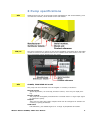
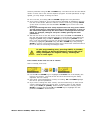
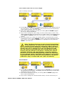
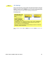
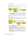
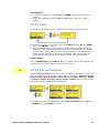
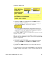
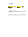
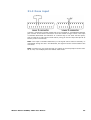
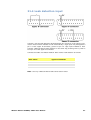
21.5.3 Logic output 3
Output 3 is taken from pin 13 of the upper D-connector, depending on the logic state
of the function assigned to Output 3. Alternatively, a load such as a relay coil may
be connected to pin 13, ground to pin 17. Current will flow through the circuit
depending on the logic state of the function assigned to Output 3. Do not connect
to any device requiring more than 50mA.
By default, output 3 is configured to indicate Auto/Man status. See 12 Switching the
pump on for the first time.
21.5.4 Logic output 4
Output 4 is taken from pin 12 of the upper D-connector, depending on the logic state
of the function assigned to Output 4. Alternatively, a load such as a relay coil may
be connected to pin 12, ground to pin 17. Current will flow through the circuit
depending on the logic state of the function assigned to Output 4. Do not connect
to any device requiring more than 50mA.
By default, output 4 is configured to indicate General alarm status. See 12 Switching
the pump on for the first time.
Watson-Marlow 620DiN, 620Di User Manual
90