1
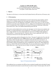
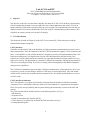
Lab 4: CAN and I2C
EE-379 Embedded Systems and Applications
Electrical Engineering Department, University at Buffalo
Last update: Cristinel Ababei, March 2013
1. Objective
The objective of this lab is to learn about Controller Area Network (CAN). We’ll do this by experimenting
with an example that on board A converts (ADC) the value of the potentiometer and sends it via CAN to
board B where the LEDs will be turned on/off by the received value. The transmitted and received data are
displayed on the LCD screens of both boards. We’ll also study I2C communication protocol and use a Wii
NunChuck to control a moving circle on the LCD display.
2. CAN Introduction
This discussion is based on Chapter 16 of the LPC17xx user manual [1]. Please take time to read the
aforementioned chapter completely.
CAN Controllers
Controller Area Network (CAN) is the definition of a high performance communication protocol for serial
data communication. The CAN Controller of the LPC1768 microcontroller (supports 2 CAN controllers and
buses; 11-bit identifier as well as 29-bit identifier) is designed to provide a full implementation of the CANProtocol according to the CAN Specification Version 2.0B. Microcontrollers with this on-chip CAN
controller are used to build powerful local networks by supporting distributed real-time control with a very
high level of security. The applications are automotive, industrial environments, and high speed networks as
well as low cost multiplex wiring. The result is a strongly reduced wiring harness and enhanced diagnostic
and supervisory capabilities.
The CAN block is intended to support multiple CAN buses simultaneously, allowing the device to be used
as a gateway, switch, or router among a number of CAN buses in various applications. The CAN module
consists of two elements: the controller and the Acceptance Filter. All registers and the RAM are accessed
as 32-bit words.
CAN Controller Architecture
The CAN Controller is a complete serial interface with both Transmit and Receive Buffers but without
Acceptance Filter. CAN Identifier filtering is done for all CAN channels in a separate block (Acceptance
Filter). Except for message buffering and acceptance filtering the functionality is similar to the PeliCAN
concept.
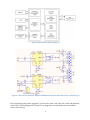
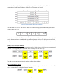
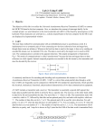
The CAN Controller Block includes interfaces to the following blocks (see Fig.1):
--APB Interface
--Acceptance Filter
--Nested Vectored Interrupt Controller (NVIC)
--CAN Transceiver (a separate chip on the MCB1700 board, shown in Fig.2)
--Common Status Registers
1
Figure 1 CAN controller block diagram [1]
Figure 2 Portion of the schematic diagram of MCB1700 board that shows the CAN1,2 connections [2]
Please read through the pointers suggested [3] to learn more about CAN. Also, take a look at the datasheet
of the NXP's TJA1040 High speed CAN transceiver integrated circuit (included in the downloadable
archive of this lab) [4].
2
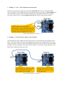
3. Example 1 – CAN2 – CAN1 loopback on the same board
The files necessary for this example are located in CAN_Keil470/ folder as part of the downloadable
archive for this lab. This is actually the whole uVision project directory. Just copy it to keil_examples/ (this
is the code-bundle of lab#2). Then clean and re-build the project. Download to the board. Connect the
serial cable as shown in Fig.3 using the adaptor from your TA. Observe operation and comment.
Figure 3 Block diagram of example 1.
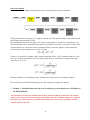
4. Example 2 – CAN2 of board A sends to CAN1 of board B
This is basically the same example as in the previous section. You do not need to create another uVision
project. To do this example, work with your neighboring team to realize the configuration shown in Fig.4.
Use the serial cable to connect CAN2 of the transmitter board (board A) to the CAN1 of the receiver board
(board B). Tune the potentiometer of board A and observe that it’s received by board B, which drives its 8
LEDs and also displays the data on the LCD.
Figure 4 Block diagram of example 2.
3
5. I2C Introduction
I2C (inter-integrated circuit) is a two wire protocol used to connect one or more “masters” with one or more
“slaves”. The case of a single master (the LPC1768) communicating with two slave devices is illustrated in
Fig.5. In this configuration, a single master (LPCxxxx) communicates with two slaves over the pair of
signal wires SCL (serial clock line) and SDA (serial data/address). Example slave devices include
temperature, humidity, and motion sensors as well as serial EEPROMs, serial RAMs, LCDs, tone
generators, other microcontrollers, etc.
Figure 5 I2C bus configuration.
Electrically, the value of the two signal wires is “high” unless one of the connected devices pulls the signal
“low”. The two pull-up resistors in Fig.5 force the default value of the two bus wires to VCC (typically
3.3V). Any device on the bus may safely force either wire low (to GND) at any time because the resistors
limit the current draw; however, the communication protocol constrains when this should occur. To
communicate, a master drives a clock signal on SCL while driving, or allowing a slave to drive SDA.
Therefore, the bit-rate of a transfer is determined by the master.
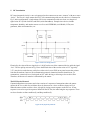
The I2C Physical Protocol:
Communication between a master and a slave consists of a sequence of transactions where the master
utilizes the SCL as a clock for serial data driven by the master or a slave on SDA as shown in Fig.6.
When the master wishes to talk to a slave, it begins by issuing a start sequence on the I2C bus. A start
sequence is one of two special sequences defined for the I2C bus, the other being the stop sequence. These
are also referred to as Start condition (S) and Stop condition (P).
Figure 6 I2C physical protocol.
4
A transaction consists of a sequence of bytes. Each byte is sent as a sequence of 8 bits. The bits of each byte
of data are placed on the SDA line starting with the MSB. The SCL line is then pulsed high, then low. For
every 8 bits transferred, the device receiving the data sends back an acknowledge bit, so there are actually 9
SCL clock pulses to transfer each 8 bit byte of data. If the receiving device sends back a low ACK bit, then
it has received the data and is ready to accept another byte. If it sends back a high (Not Acknowledge,
NACK) then it is indicating it cannot accept any further data and the master should terminate the transfer by
sending a stop sequence.
Figure 7 Illustration of sending of 1 byte of data.
The data may be sent by either the slave or the master, as the protocol dictates, and the ACK or NACK is
generated by the receiver of the data. Start (S) and Stop (P) conditions are always generated by the master.
A high to low transition on SDA while SCL is high defines a Start. A low to high transition on SDA while
SCL is high defines a Stop.
There are three types of transactions on the I2C bus, all of which are initiated by the master. These are:
write, read - depending on the state of the direction bit (R/W), and combined transactions. The first two of
these (illustrated in Fig.8) are:
(1) Write transaction - Data transfer from a master transmitter to a slave receiver. The first byte transmitted
by the master is the slave address. Next follows a number of data bytes. The slave returns an
acknowledge bit after each received byte, unless the slave device is unable to accept more data.
(2) Read transaction - Data transfer from a slave transmitter to a master receiver. The first byte (the slave
address) is transmitted by the master. The slave then returns an acknowledge bit. Next follows the data
bytes transmitted by the slave to the master. The master returns an acknowledge bit after all received
bytes other than the last byte. At the end of the last received byte, a “not acknowledge” is returned. The
master device generates all of the serial clock pulses and the START and STOP conditions. A transfer
is ended with a STOP condition or with a repeated START condition. Since a repeated START
condition is also the beginning of the next serial transfer, the I2C-bus will not be released.
Figure 8 I2C write and read transactions.
5
The LPC17xx I2C interfaces are byte oriented and have four operating modes: master transmitter mode,
master receiver mode, slave transmitter mode, and slave receiver mode. Please read Chapter 19 of the
LPC17xx user manual for details on each of these operating modes [5]. Also, please read NXP I2C-bus
specification and user manual for even more details [6].
I2C Device Addressing:
All I2C addresses are either 7 bits or 10 bits. The use of 10 bit addresses is rare. Most common chips use 7
bit addresses - we can have up to 128 devices on the I2C bus. When sending out the 7 bit address, we still
always send 8 bits. The extra bit is used to inform the slave if the master is writing to it or reading from it. If
the bit is zero the master is writing to the slave. If the bit is 1 the master is reading from the slave. The 7 bit
address is placed in the upper 7 bits of the byte and the Read/Write (R/W) bit is in the LSB.
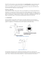
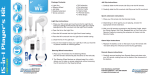
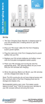
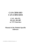
6. Wii NunChuck
The Wii NunChuk is an input device with a joystick, two buttons, and a three-axis accelerometer as
illustrated in Fig.9,10. The three axes X, Y, and Z correspond to the data produced by the accelerometer,
joystick. X is right/left, Y is forward/backwards, and Z is up/down (accelerometer only).
Figure 9 NunChuck basic information.
Figure 10 NunChuck X,Y,Z.
The NunChuck communicate via I2C. We'll hook the NunChuck to the I2C1 bus of the LPC1768
microcontroller on the MCB1700 board. We'll initialize the Nunchuk to a known state and then to regularly
“poll” its state. The data are read from the NunChuck in a six-byte read transaction. These data are
6
formatted as illustrated in Fig.11 and are read beginning with byte 0x0 (little-endian). The only
complication with this format is that the 10-bit/axis accelerometer data are split.
Figure 11 Formatting of data from NunChuck.
The NunChuck is a slave I2C bus device. It has 2 slave IDs for writing (0xA4) and reading (0xA5) data
which is shown in Fig.12.
Figure 12 Slave IDs.
Communication with the NunChuk consists of two phases – an initialization phase (executed once) in which
specific data are written to NunChuk and a repeated read phase in which the six data bytes are read. Each
read phase consists of two transactions – a write transaction which sets the read address to zero, and a read
transaction.
Initialize start NunChuk command
The initialization consists of two write transactions, each of which writes a single byte to a register internal
to the I2C slave: reg[0xf0]=0x55, reg[0xfb]= 0x00. Normally this done once only.
The read process consists of writing a 0 and then reading 6 bytes of data.
Conversion command (0x00)
Send this command to get all sensor data and store into the 6-byte register within Nunchuk controller. This
must be executes before reading data from the Nunchuk.
7
Data read command
Send the slave ID for reading (0xA5) and wait for the stream data 6-byte from the Nunchuk.
The joystick data are in the range 0..255 roughly centered at 128. The dynamic range is somewhat less than
the full range (approximately 30-220).
The accelerometer data are in the range 0..1023 where 0 corresponds to -2g and 1023 corresponds to +2g.
The accelerometer can be used both to detect motion (acceleration), but also as a “tilt sensor” when it is not
in motion because we can use the earth’s gravitational field as a reference. Suppose we have measured
values of gravity in three dimensions, Gx, Gy, Gz. Then:
From this, it is possible to compute “pitch” (rotation around the X axis), “roll” (rotation around the Y axis)
and “yaw” (rotation around the Z axis). For joystick replacement, it is sufficient to compute (after range
conversion to -512..511).
Remember that this is for 360 degrees and a reasonable of motion to measure is perhaps 90 degrees.
Please read more about NunChuck hacking in the cited references [10] and on the Internet.
7. Example 3 – NunChuck data & moving circle (according to joystick) displayed on LCD display of
the MCB1700 board
Note: Because I have only one NunChuck and a single NunChuck-adaptor, and because this example
requires some wiring, you will not actually do this example in the lab. I will demonstrate it in each of the
lab sessions or in class. However, you should read and study the source code to get familiar with this
example and how it uses I2C.
8
In this example, we use the I2C to connect the NunChuck to the board. We’ll display the data read from the
NunChuck on the 320x240 pixels display and we’ll use this data to move around a circle drawn on the
display.
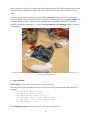
The files necessary for this example are located in I2C_NunChuck/ folder as part of the downloadable
archive for this lab. This is actually the whole uVision project directory. Just copy it to keil_examples/ (this
is the code-bundle of lab#2). Then clean and re-build the project. Download to the board. Connect the
NunChuck as shown as shown in Fig.13 using the wires provided by your instructor. Observe operation
and comment.
Figure 13 NunChuck connected to MCB1700 board. Data from NunChuck controls the movement of a
circle on the LCD display.
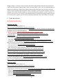
8. Lab Assignment
Pre-lab report (worth 8 points out of 20 points for this whole lab):
Write the pre-lab report and explain line by line of code the following functions from inside can.c file of
example 1:
void
void
void
void
void
void
CAN_setup (uint32_t ctrl) { ... }
CAN_start (uint32_t ctrl) { ... }
CAN_waitReady (uint32_t ctrl) { ... }
CAN_wrMsg (uint32_t ctrl, CAN_msg *msg) { ... }
CAN_rdMsg (uint32_t ctrl, CAN_msg *msg) { ... }
CAN_IRQHandler (void) { ... }
Lab assignment project (demo worth 6 points, final report worth 6 points):
9
Modify example 1 as follows: remove the part related to the ADC and add instead the part related to the
UART1 from the example studied in lab#2. In fact, from the UART1 source code you should add only the
part that sends characters typed on the keyboard of the host PC to the board. You can remove from the
UART1 code the part that sends the characters back to the host PC (which we used to display in the Putty
terminal). Here, in this modified example, we want to send character by character via CAN: send out via
CAN2 Tx and receive in via CAN1 Rx. The transmitted and received character should be displayed on the
LCD instead of the old ADC value. The received character should also drive the 8 LEDs as in example 1.
1. Credits and references
[0] Textbook, Sections 18.4,5.
References on CAN:
[1] LPC17xx user manual (Chapter 16);
http://www.nxp.com/documents/user_manual/UM10360.pdf
[2] Schematic Diagram of the MCB1700 board; http://www.keil.com/mcb1700/mcb1700-schematics.pdf
[3] Pointers on CAN related information:
-- Keil CAN Primer; http://www.keil.com/download/files/canprimer_v2.pdf
-- CAN Introduction; http://www.esd-electronics-usa.com/Controller-Area-Network-CANIntroduction.html
-- CAN Information; http://hem.bredband.net/stafni/developer/CAN.htm
-- CAN Primer; http://www.dgtech.com/images/primer.pdf
-- CAN Tutorial; http://www.computer-solutions.co.uk/info/Embedded_tutorials/can_tutorial.htm
-- Jonathan W. Valvano’s lecture 15; http://users.ece.utexas.edu/~valvano/EE345M/view15_CAN.pdf
(Note: his lectures are based on Stellaris MCU’s; however, the basics about CAN are the same)
-- Entry on Wikipedia; http://en.wikipedia.org/wiki/CAN_bus
-- CAN Specification, Version 2.0, 1991; http://esd.cs.ucr.edu/webres/can20.pdf
-- NXP’s Bosch CAN, protocol standard;
http://www.freescale.com/files/microcontrollers/doc/data_sheet/BCANPSV2.pdf
-- CAN Bus Description;
http://www.interfacebus.com/CAN-Bus-Description-Vendors-Canbus-Protocol.html
-- Marco Di Natale, Understanding and using the Controller Area Network, 2008;
http://www-inst.eecs.berkeley.edu/~ee249/fa08/Lectures/handout_canbus2.pdf
-- CAN PPT presentation at CMU; http://www.ece.cmu.edu/~ece649/lectures/11_can.pdf
[4] NXP's TJA1040 High speed CAN transceiver integrated circuit;
http://www.nxp.com/documents/data_sheet/TJA1040.pdf
References of I2C:
[5] LPC17xx user manual (Chapter 19);
http://www.nxp.com/documents/user_manual/UM10360.pdf
[6] Pointers on I2C related information:
--NXP I2C-bus specification and user manual; http://www.nxp.com/documents/user_manual/UM10204.pdf
-- tutorial 1; http://www.best-microcontroller-projects.com/i2c-tutorial.html
-- tutotial 2; http://www.robot-electronics.co.uk/acatalog/I2C_Tutorial.html
-- tutorial 3; http://embedded-lab.com/blog/?p=2583
-- Wikipedia entry; http://en.wikipedia.org/wiki/I%C2%B2C
10
[7] Lab manual of course http://homes.soic.indiana.edu/geobrown/c335 (Chapter 9).
[8] http://www.i2c-bus.org/addressing/
[9] I2C vs. SPI; http://www.byteparadigm.com/applications/introduction-to-i2c-and-spi-protocols/
[10] Pointers on NunChuck:
--Robotshop; http://www.robotshop.com/ca/content/PDF/inex-zx-nunchuck-datasheet.pdf
--Chad Philips. Read wii nunchuck data into arduino; http://www.windmeadow.com/node/42
--Wikipedia. Wii remote. http://en.wikipedia.org/wiki/Wii_Remote
--Wiibrew, Wiimote/Extension Controllers; http://wiibrew.org/wiki/Wiimote/Extension_Controllers
--Dangerousprototype, http://dangerousprototypes.com/docs/Wii_Nunchuck_quick_guide
--Freescale Semiconductor, Tilt sensing using linear accelerometers, 2012.
[11] Wii NunChuck adaptor; https://www.sparkfun.com/products/9281
APENDIX A: Listing of the main source code file for example 3
#include
#include
#include
#include
#include
#include
#include
void
void
void
void
<stdio.h>
<stdlib.h>
"lpc17xx.h"
"type.h"
"i2c.h"
"GLCD.h"
"CRIS_UTILS.h"
NunChuck_translate_data(void);
NunChuck_print_data_init(void);
NunChuck_print_data(void);
search_for_i2c_devices(void);
#define __FI 1 // Use font index 16x24
#define PORT_USED 1
#define NUNCHUK_ADDRESS_SLAVE1 0xA4
#define NUNCHUK_ADDRESS_SLAVE2 0xA5
volatile
volatile
volatile
volatile
volatile
volatile
volatile
extern
extern
extern
extern
int
int
int
int
int
int
int
joy_x_axis;
joy_y_axis;
accel_x_axis;
accel_y_axis;
accel_z_axis;
z_button = 0;
c_button = 0;
volatile
volatile
volatile
volatile
uint8_t I2CMasterBuffer[I2C_PORT_NUM][BUFSIZE]; // BUFSIZE=64
uint8_t I2CSlaveBuffer[I2C_PORT_NUM][BUFSIZE];
uint32_t I2CReadLength[I2C_PORT_NUM];
uint32_t I2CWriteLength[I2C_PORT_NUM];
char text_buffer[8];
volatile uint8_t ack_received, ack_sent; // debugging only
// we'll use delay_dirty() as a software delay function; it should produce
// about a second when del=(1 << 24) or so of delay depending on CCLK;
volatile uint32_t temp;
void delay_dirty( uint32_t del)
11
{
uint32_t i;
for ( i=0; i<del; i++) { temp = i; }
}
// Communication with the Nunchuk consists of two phases:
// -->phase 1: initialization phase (executed once) in which specific data
// are written to the Nunchuk;
// Essentially initialization consists of two write transactions,
// each of which writes a single byte to a register internal to
// the I2C slave ( reg[0xf0] = 0x55, reg[0xfb] = 0x00 ).
// -->phase 2: repeated read phase in which six data bytes are read
// again and again; each read phase consists of two transactions –
// a write transaction which sets the read address to zero, and a
// read transaction.
// NOTES:
// -- I2C0 only supports 'fast mode' that the NunChuck uses!
// -- When I2C0 is used the pin connections are: SDA=P0.27, SCL=P0.28
// -- When I2C1 is used the pin connections are: SDA=P0.19, SCL=P0.20
void NunChuck_phase1_init(void)
{
// this function should be called once only;
uint32_t i;
I2CWriteLength[PORT_USED] = 3; // write 3 bytes
I2CReadLength[PORT_USED] = 0; // read 0 bytes
I2CMasterBuffer[PORT_USED][0] = NUNCHUK_ADDRESS_SLAVE1;
I2CMasterBuffer[PORT_USED][1] = 0xF0; // at adress 0xF0 of NunChuck write:
I2CMasterBuffer[PORT_USED][2] = 0x55; // data 0x55
I2CEngine( PORT_USED );
// should I introduce a delay? people say it's useful when debugging;
delay_dirty( 0x100000 );
I2CWriteLength[PORT_USED] = 3; // write 3 bytes
I2CReadLength[PORT_USED] = 0; // read 0 bytes
I2CMasterBuffer[PORT_USED][0] = NUNCHUK_ADDRESS_SLAVE1;
I2CMasterBuffer[PORT_USED][1] = 0xFB; // at adress 0xFB of NunChuck write:
I2CMasterBuffer[PORT_USED][2] = 0x00; // data 0x00
I2CEngine( PORT_USED );
}
void NunChuck_phase2_read(void)
{
// this is called repeatedly to realize continued polling of NunChuck
uint32_t i;
I2CWriteLength[PORT_USED] = 2; // write 2 bytes
I2CReadLength[PORT_USED] = 0; // read 6 bytes;
I2CMasterBuffer[PORT_USED][0] = NUNCHUK_ADDRESS_SLAVE1;
I2CMasterBuffer[PORT_USED][1] = 0x00; // address
I2CEngine( PORT_USED );
delay_dirty( 0x10000 );
I2CWriteLength[PORT_USED] = 1; // write 1 bytes
I2CReadLength[PORT_USED] = 6; // read 6 bytes;
I2CMasterBuffer[PORT_USED][0] = NUNCHUK_ADDRESS_SLAVE2;
I2CEngine( PORT_USED );
// when I2CEngine() is executed, 6 bytes will be read and placed
// into I2CSlaveBuffer[][]
12
}
int main(void)
{
uint32_t i;
uint32_t x_prev=160, y_prev=120;
uint32_t x_new=160, y_new=120;
uint32_t dx=4, dy=4, delta=5, radius=16;
// (1) Initializations of GLCD and SER;
GLCD_Init();
GLCD_SetTextColor(Yellow);
CRIS_draw_circle(160,120, radius);
NunChuck_print_data_init();
// (2) SystemClockUpdate() updates the SystemFrequency variable
SystemClockUpdate();
// (3) Init I2C devices; though we'll use only I2C1
I2C0Init( );
I2C1Init( );
I2C2Init( );
// (4)
LPC_SC->PCONP |= ( 1
LPC_GPIO0->FIODIR |=
LPC_GPIO0->FIOCLR |=
LPC_GPIO0->FIOSET |=
<< 15 );
(1 << 21) | (1 << 22);
1 << 21;
1 << 22;
// (5) NunChuck phase 1
//search_for_i2c_devices(); // debug only purposes;
NunChuck_phase1_init();
// Note: Be careful with dirty fixed delays realized with for loops
// From device to device, or even same device with different write length,
// or various I2C clocks, such delay may need to be changed;
// however, it's good to have a break point between phases;
// (6) for ever loop
while( 1 ) {
// (a) reset stuff
for ( i = 0; i < BUFSIZE; i++ ) {
I2CSlaveBuffer[PORT_USED][i] = 0x00;
}
// (b) NunChuck phase 2
NunChuck_phase2_read();
NunChuck_translate_data();
NunChuck_print_data();
//
//
//
//
//
//
//
//
//
(c) re-draw the circle to mimic movement if necessary;
Note: joy_x_axis, joy_y_axis have values in range: 30..230
with mid-range value of about 130 when the joystick rests;
implement the simplest method to move the circle around:
->whenever joy_x_axis=190..230 (upper values in its range)
keep shifting the circle to the right;
->whenever joy_x_axis=30..70 (lower values in its range)
keep shifting the circle to the left;
->whenever joy_x_axis is in the mid-range do not move circle
13
//
//
//
//
if
apply same logic for joy_x_axis
TODO (assignments): move the circle based on the rotations
i.e., do not use joystick; use buttons Z and C to increase
or decrease the radius of the circle displayed on LCD;
(joy_x_axis > 190) {
dx = delta;
} else if (joy_x_axis < 90) {
dx = -delta;
} else {
dx = 0;
}
x_new = x_prev + dx;
if (x_new > 320 - radius) x_new = 320 - radius;
if (x_new < 0 + radius) x_new = radius;
if (joy_y_axis > 190) {
dy = -delta;
} else if (joy_y_axis < 90) {
dy = delta;
} else {
dy = 0;
}
y_new = y_prev + dy;
if (y_new > 240 - radius) y_new = 240 - radius;
if (y_new < 0 + radius) y_new = radius;
if ( (x_new != x_prev) || (y_new != y_prev)) { // must move circle;
// first erase the circle at previous location;
GLCD_SetTextColor(Black);
CRIS_draw_circle(x_prev,y_prev, radius);
// then re-draw at new location;
GLCD_SetTextColor(Yellow);
CRIS_draw_circle(x_new,y_new, radius);
}
x_prev = x_new;
y_prev = y_new;
// (d) long delay such that I have enough time to release joystick
// and have the circle stay at new location; this is a hack
// and should be modified to work nicely and to use rotations;
delay_dirty( 0x10000 );
}
}
void NunChuck_translate_data(void)
{
int byte5 = I2CSlaveBuffer[PORT_USED][5];
joy_x_axis = I2CSlaveBuffer[PORT_USED][0];
joy_y_axis = I2CSlaveBuffer[PORT_USED][1];
accel_x_axis = (I2CSlaveBuffer[PORT_USED][2] << 2);
accel_y_axis = (I2CSlaveBuffer[PORT_USED][3] << 2);
accel_z_axis = (I2CSlaveBuffer[PORT_USED][4] << 2);
z_button = 0;
c_button = 0;
// byte I2CSlaveBuffer[PORT_USED][5] contains bits for z and c buttons
// it also contains the least significant bits for the accelerometer data
if ((byte5 >> 0) & 1)
z_button = 1;
if ((byte5 >> 1) & 1)
14
c_button
accel_x_axis
accel_y_axis
accel_z_axis
= 1;
+= (byte5 >> 2) & 0x03;
+= (byte5 >> 4) & 0x03;
+= (byte5 >> 6) & 0x03;
}
void NunChuck_print_data_init(void)
{
// this should be called once only;
GLCD_SetTextColor(White);
GLCD_Clear(Black); // clear graphical LCD display; set all pixels to Black
GLCD_SetBackColor(Black); // set background color for when characters/text is printed
GLCD_SetTextColor(White);
GLCD_DisplayString(0, 0, __FI, " This is I2C example");
GLCD_DisplayString(1, 0, __FI, " Data from NunChuck:");
GLCD_DisplayString(2,
GLCD_DisplayString(3,
GLCD_DisplayString(4,
GLCD_DisplayString(5,
GLCD_DisplayString(6,
GLCD_DisplayString(7,
GLCD_DisplayString(8,
2,
2,
2,
2,
2,
2,
2,
__FI,
__FI,
__FI,
__FI,
__FI,
__FI,
__FI,
"joyX
"joyY
"accX
"accY
"accZ
"Z
"C
=");
=");
=");
=");
=");
=");
=");
}
void NunChuck_print_data(void)
{
// this is called as many times as reads from the NunChuck;
GLCD_SetTextColor(White);
sprintf(text_buffer, "%03d", joy_x_axis);
GLCD_DisplayString(2, 10, __FI, (uint8_t*)text_buffer);
sprintf(text_buffer, "%03d", joy_y_axis);
GLCD_DisplayString(3, 10, __FI, (uint8_t*)text_buffer);
sprintf(text_buffer, "%04d", accel_x_axis);
GLCD_DisplayString(4, 10, __FI, (uint8_t*)text_buffer);
sprintf(text_buffer, "%04d", accel_y_axis);
GLCD_DisplayString(5, 10, __FI, (uint8_t*)text_buffer);
sprintf(text_buffer, "%04d", accel_z_axis);
GLCD_DisplayString(6, 10, __FI, (uint8_t*)text_buffer);
sprintf(text_buffer, "%01d", z_button);
GLCD_DisplayString(7, 10, __FI, (uint8_t*)text_buffer);
sprintf(text_buffer, "%01d", c_button);
GLCD_DisplayString(8, 10, __FI, (uint8_t*)text_buffer);
}
15