1
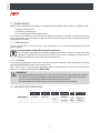
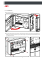
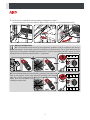
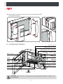
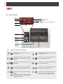
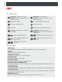
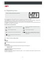
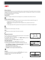
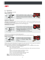
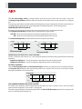
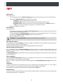
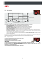
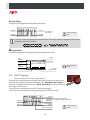
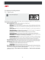
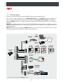
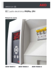
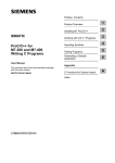
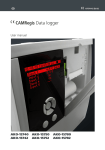
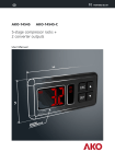
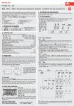
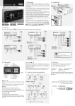
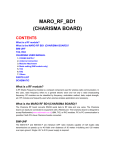
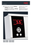
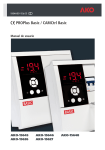
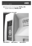
1565H202 Ed.01 GB
PROPlus 3PH Electronic Panel
User Manual
AKO-15651-3
AKO-15652-3
AKO-15653-3
Index
Page
1.- Presentation ..............................................................................................................................3
1.1.- Maintenance...................................................................................................................3
1.2.- Cautions..........................................................................................................................3
2.- Versions and references...............................................................................................................3
3.- Installation.................................................................................................................................4
4.- Component location ...................................................................................................................6
5.- Recommendations .....................................................................................................................7
6.- Description ................................................................................................................................8
6.1.- Quick access to functions ..................................................................................................8
6.2.- Status LEDs......................................................................................................................9
6.3.- Messages ........................................................................................................................9
7.- Wiring .....................................................................................................................................10
7.1.- Pressure controller wiring options ..................................................................................11
8.- Programming menu .................................................................................................................12
8.1.- Basic initial configuration................................................................................................12
9.- Operation ................................................................................................................................15
9.1.- Compressor control ......................................................................................................15
9.2.- Defrost control ..............................................................................................................17
9.3.- Fan control....................................................................................................................19
9.4.- Light control ..................................................................................................................19
9.5.- Pump down function ......................................................................................................20
9.6.- Alarms...........................................................................................................................21
9.7.- Data logging..................................................................................................................22
9.8.- HACCP logging ..............................................................................................................23
10. Advanced configurations ..........................................................................................................24
10.1.- Digital inputs...............................................................................................................24
10.2.- Auxiliary relay ..............................................................................................................25
10.3.- Access code (password) ................................................................................................26
10.5.- Return to initial parameters...........................................................................................26
10.6.- Program version...........................................................................................................26
11.- Connectivity...........................................................................................................................27
12.- Wiring diagrams .....................................................................................................................28
13.- Parameters.............................................................................................................................32
14.- Technical specifications...........................................................................................................37
AKO Electromecànica thanks you and congratulates you on the purchase of our product, the development and manufacture of which
involved the most innovative technologies, as well as rigorous production and quality control processes.
Our commitment to achieving customer satisfaction and our continuous efforts to improve day by day are confirmed by the various
quality certificates obtained.
This is a high performance, technologically advanced product. Its operation and the final performance achieved will depend, to a great
extent, on correct planning, installation, configuration and commissioning. Please read this manual carefully before proceeding to install
it and respect the instructions in the manual at all times.
Only qualified personnel may install the product or carry out technical support.
This product has been developed for use in the applications described in the manual. AKO Electromecànica does not guarantee its
operation in any use not foreseen in this document and accepts no liability in the case of damage of any type which may result from
incorrect use, configuration, installation or commissioning.
Complying with and enforcing the regulations applying to installations where our products are destined to be used is the responsibility of
the installer and the customer. AKO Electromecànica accepts no liability for damage which may occur due to failure to comply with these
regulations. Rigorously follow the instructions described in this manual.
In order to extend the lifetime of our products to the maximum, the following points must be observed:
Do not expose electronic equipment to dust, dirt, water, rain, moisture, high temperatures, chemical agents or corrosive
substances of any type.
Do not subject equipment to knocks or vibrations or attempt to handle them in any way differently to that indicated in
the manual.
Do not under any circumstances exceed the specifications and limitations indicated in the manual.
Respect the indicated environmental conditions for operation and storage at all times.
During installation and on completion of this, avoid the presence of loose, broken or unprotected cables or cables in poor
condition. These may constitute a risk for the equipment and its users.
AKO Electromecànica reserves the right to make any modification to the documentation and the product without prior notification.
2
1.- Presentation
PROPlus 3PH is the global electronic solution to manage positive and negative cold room stores, in combination with:
ŸStandard condensing units
ŸStreamlined condensing units
ŸOr as a service panel in decentralised systems.
It has a general circuit breaker of up to 25A, high IP65 degree of protection for installation in damp environments, is
easy to install thanks to its new connection strip and intuitive menus with help texts that make programming easier
using its backlit LCD display.
1.1.- Maintenance
Clean the surface of the unit with a soft cloth, water and detergent. Do not use abrasive detergents, petrol, white
spirits or solvents.
Units that include rechargeable electrical accumulators:
This unit includes accumulators that should be replaced when the unit's battery life is under the duration
assigned in its specifications. At the end of the useful life of the unit, the accumulators should be taken to a
selective waste collection centre or returned to the manufacturer.
1.2.- Cautions
Using the unit not observing the manufacturer's instructions may alter the appliance's safety requirements. Only probes
supplied by AKO should be used for the it to operate correctly.
From –40 ºC to +20 ºC, if the NTC probe is extended to 1000 m with at least 0.5 mm2 cable, the maximum deviation
will be 0.25 ºC (cable for probe extension ref. AKO-15586).
IMPORTANT:
ŸThe function of each probe depends on the "probe setting" parameter (See probe configuration on page 13).
ŸThe AUXILIARY relay is programmable, and its operations depends on the configuration (See page 25).
ŸThe function of the digital inputs depends on the configuration (See page 24).
ŸThe recommended currents and powers are the maximum working currents and powers.
2.- Versions and references
Condensing
unit
Condenser
fans
AKO-15651-3
4 - 6.3 A
0.63 - 1 A
AKO-15652-3
6.3 - 10 A
1 - 1.6 A
AKO-15653-3
10 - 12 A
1 - 1.6 A
Evaporator
fan
Defrost
resistances
Light
Power supply
2A
(460 W)
400 V / III
50/60 Hz
7.000 W
3A
3
10.200 W
3.- Installation
A.- Open and remove cover.
90º
B.- Using the included template, make 4 holes in the wall and fasten the unit to the wall using the supplied screws.
Make a hole in the bottom of the box to pass the cables through, and a suitable gland should be used to main the
IP65 degree of protection.
255
355
4
C.- Put the cover on, and make the wiring according to the diagrams in section 7.
Connect the battery (1), the control cable (2), adjust the motor guard (Q1 and Q2) and close the cover (3).
2
1
3
Motor guard adjustment
Q1: Put an ammeter clamp into one of the compressor's conductors. Start the compressor and check its
consumption. Set the motor guard (Q1) according to the obtained value. The set value should never be
higher than the consumption indicated by the manufacturer. If a fan is connected to the FAN 1 output, Q1 will be
adjusted to the sum of both consumptions (FAN 1 + compressor).
16
10
Q1
10
16
A
I
A
O
A
1.5
1
A
0.8
FAN 1
1.
6
1
Q2
I
16
Q2: Put an ammeter clamp into one of the fan's conductors. Start the fan and
check its consumption. Set the motor guard (Q2) according to the obtained
value. The set value should never be
higher than the consumption indicated by the manufacturer.
1
A
O
A
FAN 2
5
0.8
D.- Remove the front trims (A) and screw the cover on using the included screws (B).
Then install the trims again.
B
C
A
C
C
4.- Component location
F1: Circuit breaker
FM: Operating circuit breaker
Q1: Compressor and fan 1 motor guard
Q2: Fan 2 motor
guard
Battery connector
K2M: Defrost
contactor
Control
terminal
F2: Auxiliary
output fuse
Control
cable
connector
K1M: Compressor
contactor
Single phase
terminal
K3M: Fan contactor
Three phase
terminal
ATTENTION: Make sure to turn of the equipment's power supply before handling it, as different areas
may be energised.
6
5.- Recommendations
Disconnect the voltage before carrying out any operations inside the electrical panel. All wiring should be according to
current standards and should be carried out by authorised staff. Only carry out the wiring foreseen in the wiring
diagrams. Using the electrical panel not observing the manufacturer's instructions may alter the appliance's safety
requirements. A tool is needed to remove any fixed part.
Panel installation:
It is advisable to leave a clean safety space without obstacles around the panel.
Do not knock or make sudden movements on the panel.
Carry out the wiring according to the installation manual.
The probes and their cables should NEVER be installed in a conduit together with power, control or feeder cables.
The earth terminals that the panels contain are installed to guarantee the continuity of earthing, however, earthing is
not carried out by the terminal and should be carried out outside the panel.
The neutral ratings are of the TT type. The IT rating should not be used.
Circuit breakers (protective switches) are of the phase/s + neutral, curve C type, guaranteeing switching and protection
against overcurrents.
Close the panel when your are not working on it.
Residual current protection outside the electrical panel according to low voltage electrotechnical regulations.
The panels meet European standard EN 61439-1.
Terminals for copper external conductors.
Checks before starting the panel up:
Power supply voltages and frequencies will be the ones that figure in the "Technical specifications" section.
Check that there are no loose parts or foreign bodies on connections or switchgear.
Check that there is no dust or damp inside the panel.
Check the correct fastening of the switchgear and components.
Check the correct tightening of the screws and power connections.
Check the correct connection of the power conductors.
Check the correct insulation of the outer lines and that they do not mechanically force the inner connections of the panel.
Check that the maximum current of the Q1 current breaker.
Before starting the installation up, we recommend preheating the compressor's housing.
Checks during the panel start-up:
Check that no electric arcs occur.
Check that the relays or contactors do not produce ratios.
Check that there is no overheating in cables, controllers and the rest of the switchgear.
Checks after the first 24 hours of operation:
Check that no overheating occurs.
Retighten screws and power connections.
Periodical preventive maintenance:
The panel should remain closed using its lock.
Retighten the power connections once a year.
Check the wear of the switchgear once a year.
Clean the outer surface of the panel with a soft cloth, water and detergent. Do not use abrasive detergents, petrol,
white spirits or solvents.
Technical data:
Working ambient temperature: –5 ºC to 40 ºC
Rated isolation voltage Ui = 440 V~
Electrical panels with degree of protection: IP 65
CEM B environment
Terminals for copper conductors
Resistance to short-circuits Icc=6 kA
Rated pulse voltage (Vimp) 2,5 KV
Cable isolation voltage:
Operation: 500V (Halogen free)
Power: 750V (Halogen free)
7
6.- Description
Date
Time
Battery status
Day of
the week
Temperature
Loading finished
Loading
Faulty or not connected (flashing)
Status
indicators
Display
Browser
Escape key
Help key
Safety cover
Electrical
protections
6.1.- Quick access to functions
SET
SET
Pressing it for 5 seconds activates or deactivates the defrost.
Pressing it for 5 seconds activates or deactivates the AUX relay. (According to config. see
page 25).
SET
Pressing it for 5 seconds allows changing the
SET POINT temperature.
SET
Pressing it for 5 seconds activates or deactivates the CONTINUOUS CYCLE.
SET
Pressing it for 5 seconds accesses the log list
(See page 22).
SET
Pressing it for 5 seconds accesses the HACCP
events log (See page 23).
SET
Pressing it for 5 seconds accesses the display
contrast setting, press N and Q to change it.
SET
Pressing it for 5 seconds allows editing the
description of the unit (See page 14).
Silences the alarms (they are indicated on the
display).
Pressing it for 5 seconds activates or deactivates the Stand-By mode. The display shows
the m symbol in this mode.
¿
ESC
8
It activates or deactivates the cold room light
(terminals 11 and 12). This function stays
active although the unit is in the m mode.
6.2.- Status LEDs
Permanent: Compressor relay active.
Flashing: It must be activated, but it is not
due to a parameter.
Permanent: Fan relay activated.
Flashing: It must be activated, but it is not
due to a parameter.
Defrost relay activated.
Defrost ended by time (See page 18).
Continuous cycle mode active.
Light relay activated.
Alarm active.
Energy saving mode active (See page 15).
Flashing: Alarm silenced + alarm relay
deactivated.
Permanent: HACCP function active.
Flashing: HACCP alarm stored not displayed
(See page 23).
Auxiliary relay activated by key.
Auxiliary relay activated per digital input.
Auxiliary relay indicating the unit's
status (ON/OFF).
Auxiliary relay active in second defrost
mode.
Auxiliary active relay in pump
down mode.
6.3.- Messages
ACCESS CODE:
Access code (password) request to enter to the programming menu or to change the set point.
DEFROST:
Indicates that a defrost is being performed.
THERMOSTAT CONTROL:
The thermostat control function is active (See page 15).
EXTERNAL ALARM:
Fan 2 motor guard has been tripped (Q2).
SEVERE EXT. ALARM:
Severe external alarm activated by one of the digital inputs.
HIGH TEMP. ALARM / LOW TEMP. ALARM:
The temperature of probe 1 exceeds / is lower than the parameter programmed in Maximum alarm probe 1 /
Minimum alarm probe 1.
L. PRESSURE ALARM:
The low pressure controller has triggered due an excessively low pressure in the low pressure circuit, adjustment stops.
COMP. SAFE. ALARM:
It indicates that a component in the compressor's safety chain has triggered (compressor motor guard,
thermistors or high pressure controller).
ERROR PROBE 1, 2, or 3:
Probe 1, 2 or 3 broken (circuit open, crossed or temperature> 110 ºC or temp.<–55 ºC).
9
7.- Wiring
Three phase terminal
*CONDENSER
PE L1 L2 L3 N
FAN
2
U
V W U1 V1 W1 U2 V2 W2 R1 R2 R3 N1 PE
U
V
W
CONDENSING
UNIT
W
V
U
W
COND.
FAN 2*
L1 L2 L3
COND.
FAN 1*
FAN FAN
1
2
Control terminal
MODBUS
RS-485
V
U
TT 400 Vac
50Hz
N
DEFROST
RESISTANCE
Single phase terminal
GND
3
Tr
Tr
4
7
8
L
N
9 10 11 12 13 14 15 16 17 18 19 20 21 22 23 24 25
4
Digital
input 2
L
N
L
3
C A B
N
Q2
Digital
input 1
LIQUID
SOLENOID
VALVE 2
LIGHT
230 V~
460 W
CRANKASE
HEATER
S1
HIGH/LOW
PRESSURE
CONTROLLER
(See page 11)
S2
1
4
L
N
L
N
ALARM
RELAY
S3
NO
C
NC
L
N 14 11
1
4
B1
8A
FAN
PRESSURE 4
CONTROLLER
(See page 11)
EVAP. FAN
1690 W (3 A)
1
AUXILIARY.
POWER
SUPPLY
230 V~1500 W
B2
1
THERMISTORS
AUX.
DEFROST.
THERM. 3
If the installation does not have a thermistor a bridge should be made between the 17 and 19 terminals,
and terminal 18 will remain free. The bridge can be replaced by an external command.
2
The auxiliary relay output function (terminals 15 and 16) is configurable (See page. 25), the default
function is "Pump down" (connection to liquid solenoid valve).
3
If the installation have a defrost thermostat, a bridge between terminals 23 and 24 should be removed.
4
If the installation has a fan pressure controller, the bridge between terminal 3 and 4 should be removed.
10
7.1.- Pressure switch wiring options
Combine high-low pressure controller (preset option)
Three phase terminal
PE
Single phase terminal
Configuration
Pressure controller: Dual HP-LP
20 21 22
LP
HP
Separate Low pressure controller per AC input
Configuration
Three phase terminal
PE
Single phase terminal
20 21 22
Pressure controller: LP indep. AC input
25
HP
LP
Separate Low pressure controller per digital input
Configuration
20 21 22
HP
Control terminal
Digital
input 2
Tr
Tr
GND
PE
Single phase terminal
Digital
input 1
Three phase terminal
Pressure controller : LP indep. dig. input
Input 2 : Low switch input
Input 2 polarity: Normally closed
LP
Pressure controller equivalence
FAN CONTROL
DANFOS/
ALCO / RANCO
PENN
HIGH / LOW
DANFOS/
PENN
ALCO
RANCO
3
4
3
4
20 21 22
20 21 22
20 21 22
1
4
A C
C A B
14 21 12 22 11
4
11
1
2
8.- Programming menu
It allows configuring the operating parameters.
The programming menu allows adjusting the unit's parameters to the installation's needs.
Press the SET key for 5 seconds to access the programming menu. If the access code is activated, a 2 digit code is
requested (See page 26), if the code entered is not correct the unit will not enter programming.
The parameters are grouped by functions in 12 separate menus, to access a given menu, select it using the browser and
press SET (For more details, consult page 32).
Function of the keys in programming
SET
Moves the selection up, or increases the value of the
parameter.
SET
Moves the selection down or decreases the value of
the parameter.
SET
Moves the selection to the left.
SET
Moves the selection to the right.
SET
Accepts the value or accesses the selected menu.
ESC
Allows exiting a parameter without saving the
changes, returning to the previous menu or exiting
programming.
Displays the help for the selected parameter or
function.
¿
8.1.- Basic initial configuration
3
Language
It defines the language of the menus and helps displayed on the screen.
G
Set point (SP)
It defines the temperature that should be inside the cold storage room (See page 15):
ŸMinimum: –40.0 *
ŸMaximum: 320 *
*(Depends on the bottom/top locking of the set point).
Calibration of Probe 1
It allows correcting the temperature detected by probe 1, this is particularly useful when the probe cannot be
located in the ideal place.
12
q
Connected sensors
Choose the correct option according to the no. of probes connected:
ŸSensor 1: If it has just one control probe. Defrost will end by time.
ŸSensor 1 and 2: If it has two probes, a control probe and another one for defrost (evaporator).
ŸSensor 1 and 3: If it has two probes, one for control and another for data logging or product temperature
(according to Probe setting), defrost will finish by time.
ŸSensor 1, 2 and 3: If it has three probes, one for control, and another for defrost and another for data
logging or product temperature (according to Probe setting).
Sensors to be displayed
It defines which probe will be displayed on the screen (probe 1, probe 2 or probe 3).
Display mode
It defines the information displayed on the screen during normal operation:
ŸProbe and clock: It displays the probe defined in the Sensors to be displayed parameter, the date, time
and day of the week.
ŸProbe and text: It displays the probe defined in the Sensors to be displayed parameter and the
description of the unit (See page 14).
ŸProbes, clock and text: It displays all the active probes, date, time and day of the week and the description
of the unit (See page 14). The configuration of the Sensors to be displayed does not intervene in this
mode.
Display unit
It defines the temperature display units (º Centigrade or º Fahrenheit).
Probe setting
It defines the function of the inputs of probe S1 and S3, the function of the S2 input is not configurable.
ŸTEM at S1/REG at S3: The temperature control, alarms and HACCP probe (Probe 1) is connected to the
S1 input and the temperature data logger probe (Probe 3) to the S3 input:
TEM at S1/REG at S3 (According to EN 12830)
S1
S2
S3
CON4
Probe 1 (Control of temperature, alarms and HACCP)
Probe 2 (Defrost / 2nd defrost)
Probe 3 (Data logger / 2nd defrost)
If probe 3 is configured as 2 defrost, the data logging deactivates.
ŸTEM and REG at S3: The temperature control, alarms and HACCP probe is also the data logger probe
(Probe 1) and it is connected in input S3, the product temperature probe is connected in the S1 input.
TEM and REG at S3
S1
S2
S3
CON4
Probe 3 (Product temperature probe / 2nd defrost)
Probe 2 (Defrost / 2nd defrost)
Probe 1 (Control of temperature, alarms, HACCP and data logger)
13
Delay at Start-up
They allow delaying the start up of the installation when it receives electricity. This parameter prevents continuous
stoppages and start-ups of the installation in exceptional situations, for example, after a power cut, in test periods
or during the commissioning of the installation.
This is established in minutes.
Decimal point
It defines is the degree's decimal points are displayed or not, and therefore the resolution of the unit.
v
Pressure controller config.
It chooses the correct option depending on the type of pressure switch and their connection (See page 11):
ŸCombined HP-LP: A HP-LP pressure switch is used.
ŸLP indep. AC input: The low pressure switch is separate and is connected to the AC input
(Terminal 22).
ŸLP indep digital input: The low pressure switch is separate and is connected to the digital input 2.
u
Date
If configures the current date (year, month, day).
Hour
If configures the current time (day of the week, day, minute).
A
Equipment description
The unit's display can be customised including the description of the installation
with a maximum length of 25 characters.
The description will not be displayed if the Display mode parameter is
configured as “Probe 1 and clock”.
To edit the description, press the SET and O keys for 5 seconds.
Text editor operation
To change the description, press the SET + O keys at the same time.
The changes made during edition are displayed on the bottom of the screen.
ŸUse the P, O, N and Q keys to move around the different characters and
options available and the SET key to validate the selection.
ŸSelect 9 to delete the character in grey.
ŸSelect L or K to move around the text being edited.
ŸSelect 8 to save the changes and exit the edition menu.
:
Contrast
To change the contrast of the screen, press the SET and O keys for 5 seconds.
Adjust the screen's contrast pressing the N and Q keys.
Press SET to validate.
14
9.- Operation
9.1.- Compressor control
NORMAL OPERATION
When the temperature in probe 1 reaches the set
point value (SP) plus the probe's differential, the
compressor activates and makes the temperature
drop. When the set point value (SP) is reached, the
compressor stops.
ON
COMP.
OFF
ºC
SP
SP+Dif.
CONTROL BY THERMOSTAT
Temperature is controlled by an external thermostat instead of probe 1, and to do so one of the digital inputs must be
configured as "Thermostat control".
This configuration cancels the probe inputs, and therefore temperatures will not be displayed nor will the functions
associated with them be carried out (temperature, alarms, HACCP logging, etc.).
CONTINUOUS CYCLE MODE
ON
COMP.
OFF
ºC
Continuous SP
Cycle Duration
SP+C1
When this mode is activated, the compressor starts
to operate continuously and without taking the set
point into account, until the time configured in the
Continuous cycle duration parameter passes, or
until the O key is pressed again for 5 seconds.
The unit will immediately return to normal operation.
Use this function to cool the cold rooms before loading products.
It is activate pressing the O key for 5 seconds, the display shows the % icon while this mode is active.
ENERGY SAVING MODE
ON
COOL
OFF
ºC
SP2
(SP2)+Dif.
Operation is the same as in the normal ode, but
increasing the set point the amount of degrees
defined in the Set point energy saving
parameter.
(SP2= Set point during energy saving)
It allows energy saving in the periods of low activity of the cold room, and in this way reduces the installation's
electricity consumption. The display will show the Z icon when this mode is active.
It is activated using time programming, using the Energy saving start parameter on the u menu with the options:
ŸDay: Defines the days this mode will be activated on;
žDeact.: It will never be activated.
žMonday/Tuesday/Wednesday/Thurdsay/Friday/Saturday/Sunday: It will only activate on the chosen
day.
žMon-Sun: It will activate everyday (from Monday to Sunday).
žMon-Sat: It will activate everyday except Sunday.
žMon-Fri: It will activate everyday except Saturday and Sunday.
žSat-Sun: It will only activate on Saturday and Sunday.
ŸHour: It times the energy saving mode start hour.
ŸMinute: It times the energy saving mode start minute.
15
The Set point energy saving parameter defines what the set point will be when this mode is active and
the Energy saving duration parameter defines the duration of this mode in hours. It never activates if it is configured
at 0.
This mode may optionally be activated and deactivated whenever you want using the external button connected to one
of the digital inputs, and to do so the corresponding input should be configured as "Remote energy saving”.
COMPRESSOR PROTECTION DELAY
This protects the compressor, preventing continuous stops and start-ups in certain exceptional cases.
The Comrpessor Protection parameter allows choosing between 2 types of delay:
OFF-ON: Minimum time the compressor should stay stopped before each start-up.
ON: Minimum time the compressor should stay operating before each start-up.
The Protection delay time parameter defines the time of the previous parameter.
OFF-ON
SP
ON
SP+Dif.
SP+Dif.
ON
ON
COMP.
COMP.
OFF
OFF
Delay time
SP
Delay time
Time
Time
OPERATION IN THE EVENT OF A FAULT IN PROBE 1
If probe 1 fails (failure, disconnection, etc. ), the compressor operates according to times programmed in the following
parameters:
Compressor ON fault s1: Time of the compressor operating in the event of a fault in probe 1.
Compressor OFF fault s1: Time of the compressor stopped in the event of a fault in probe 1.
SET POINT LOCKINGS
Using the Set Point upper limit and Set Point lower limit parameters, it is possible to set a top and bottom limit for
the Set point (SP) parameter, which prevents being able to set a set point that is too low or too high that might
damage the installation or the stored product.
Fault in Probe 1
ON
COMP.
OFF
Time
COMP.
ON
COMP.
OFF
COMP.
ON
COMP.
OFF
STOP COMPRESSOR WHEN THE DOOR IS OPENED
This defines if the compressor will be stopped whenever the cold room's door is opened. To do so, one of the digital
inputs should be configured as "door contact" (See page 24).
If the door stays open longer than the value programmed in the Inact. with door open parameter, the compressor will
return to normal operation (See page 24).
16
9.2.- Defrost control
Max. B
C
FAN START UP DELAY
CONTROL
DEFROST
"DEF”
"DEF"MESSAGE
MESSAGE
DRIP
DRIP TIME
TIME
ºC
CONTROL
DEFROST
DEFROST
A
D
SP+Dif.
SP
time
A
B
C
D
SP
Dif.
Description
Parameter
Time between two defrost starts
Maximum defrost duration
Maximum duration of the defrost message
Final defrost temperature by probe 2
Temperature set point
Temperature set point differential
Defrost frequency
Defrost duration
Message duration
Defrost final temperature
Set point (SP)
Sensor 1 differential
Type of defrost
This is chosen using the Defrost type parameter that defines the behaviour of the controller during the defrost
process.
Types of
defrost
Compressor
stopping
By air
By resistances
Description
Parameter configuration
The compressor stops and defrost is carried out statically.
H Defrost type: Resistances
X Fans state during defrost: Disconnected
The fans are activated and the compressor stops, defrost is
carried out forcing the movement of air through the
evaporator.
H Defrost type: Resistances
X Fans state during defrost: Connected
The defrost resistances are activated and the compressor stops, H Defrost type: Resistances
defrost is carried out by the heat supply from the resistances.
X Fans state during defrost: Disconnected
REMARK: Defrost by hot gas bypass cannot be used in these units.
17
Defrost start
Defrost will start if:
ŸThe time programmed in the Defrost frequency parameter has passed since the start of the last defrost.
The parameter Defrost mode defines how this time is counted:
žFrequency: Total time passed between defrost starts.
žCompressor sum: Total time of the compressor operating between defrost starts.
žReal Time Clock: Defrost starts when one of the times programmed in the Defrost 1 to 8 on
the u menu is reached. (The defrost frequency is not taken into account).
ŸWe press the N key for 5 seconds.
End of defrost
The defrost stops if:
ŸThe temperature programmed in the Defrost final temperature has been reached in probe 2 (this requires
having a defrost probe connected to S2).
ŸThe time configured in the Defrost duration has passed (maximum defrost duration). The I icon is shown on
the display if the Signals end defrost time parameter is configured in “Yes”.
ŸWe press the N key for 5 seconds.
REMARK: If the Defrost duration is configured to 0, no defrosts are carried out.
Drip time after defrost
This is establishing using the Drip time parameter of the H menu and defines the time added at the end of the defrost
to allow removing any water left in the evaporator.
During this time, the compressor and fans will be stopped (except if the defrost is by air).
Message displayed during defrost
This is established using the Defrost message parameter, and you can choose between displaying the real
temperature captured by probe 1, show the temperature capture by probe 1 at the start of the defrost, or display the
DEFROST message.
The Message duration parameter defines how long this message is displayed, after the drip time and start up delay of
the fans (See page 17).
Other parameters
Using the Defrost at Start-up parameter, you can configure if the unit carries out or not a defrost when it receives
power (first start up or after a fault in the power supply).
If the "YES" option is chosen, defrost starts after the time defined in the Defrost delay at Start-up parameter on the
H menu.
2nd defrost
It operates in the same way as the defrost, but acts on the auxiliary relay, controlled by probe 2 or 3 and is used to
control the defrost in a second evaporator. (The AUX relay must be configured as 2nd defrost).
The configuration parameters of the 2nd defrost are configured from the v menu.
Remote defrost
This function allows activating the defrost of the unit using an external button, connecting it to one of the digital inputs
that must be configured as "remote defrost”.
18
9.3.- Fan control
ON
COMP.
OFF
ON
Only if “Stop if
compressor OFF?”=Yes
VENT.
OFF
TEMP. ºC
in
probe 2
Time
Differential fan S2
Temp. fan stop
Fan control is carried out using probe 2 and taking the following parameters into account:
ŸFan stop temperature: It defines the temperature at which the fans stop.
ŸFans differential s2: It defines the temperature differential of probe 2 (evaporator).
ŸStop when compressor OFF?: It defines if the fans stop in each compressor stop.
ŸFans state during defrost: It defines the status of the fans during the defrost.
ŸFans delay after defrost: If configures the time that passes before starting the fans up, at the end of a defrost.
ŸStop when opening door: It defines if the fans are stopped when the cold room's door is opened (this requires
having configured one of the digital inputs as door contact).
If the door stays open longer than the value programmed in the Inact. with door open parameter, the fans
return to normal operation.
If probe 2 is not connected or an error in the probe is detected, the fans will always be operating without taking into
account the temperature related parameters, but taking the rest of the parameters into account.
9.4.- Light control
The unit has an additional relay to control the cold room's lights.
Just press the ? key to turn the lights on/off.
This function is even active when the unit is in Stand-by.
Light timing
The unit activates the lights whenever the cold room's door is detected to have been opened, and turns them off after
the time programmed in the Cold room light timing parameter, even though the door stays open. If time is
configured at “0”, timing does not start.
One of the digital inputs should be configured as "Door contact”.
19
9.5.- Pump down function
This function foresees problems in the compressor caused by movements of coolant, using a stop/start technique of the
installation, controlled via the liquid solenoid, the low pressure controller and the compressor itself.
The auxiliary relay must be configured as "Pump down control" (default configuration), the liquid solenoid must be
connected to the 15 and 16 terminals and there must be a low pressure controller connected as indicated in the
diagrams (See page 10).
STOP
When the temperature in probe 1 reaches the set point (SP) value, the liquid solenoid closes.
Due to the compressor continuing to operate (COMP. relay ON), the pressure drops quickly in the evaporator, and
therefore activates the low pressure controller and the compressor stops.
If during this process the low pressure controller does not detect the change of pressure, the controller will stop after the
safety time defined in Pump down duration.
START
When the temperature in probe 1 reaches the set point value plus the differential, the liquid solenoid opens, making the
pressure in the evaporator increase and deactivating the low pressure controller, which will start the compressor up.
When a balance is reached between the high and low pressure before the start up, this is much gentler and lengthens
the life of the compressor.
If after a time after opening the liquid solenoid the low pressure controller does not deactivate, the controller closes the
solenoid again and activates the low pressure alarm. This time is defined using the Pump down On delay parameter.
STAND-BY WITH PUMP DOWN
If the pump down function is active and the compressor is operating, when the Stand-by function starts the unit stops
the compressor in a controlled manner as explained in the "STOP" section and displays on the screen the "Pump
down" message, and when it has finished, it automatically goes to the Stand-by mode.
Liquid solenoid
ON
AUX
OFF
Low pressure
controller
ON
Digital
input
OFF
Fault in pressure
controller
ON
Compressor
Fault in pressure
controller
COMP.
OFF
+
Pressure in
evaporator
Time
Low Pressure
Alarm
SP
SP+DIF.
SP
20
Pump
down
duration
SP+DIF.
Pump
down
On
delay
9.6.- Alarms
The unit warns the user with a message on the screen of the activation of a relay or the
activation of an acoustic signal in certain circumstances, according to the programming of
the following parameters:
Alarm configuration
It defines how the values of the different temperature alarms are defined:
Relative to the SP: They are defined indicating the temperature variation regarding the set point for the alarm to
activate. This option enables us to change the set point without having to reset the maximum
and minimum alarms.
Absolute:
They are defined indicating the absolute temperature value for the alarm to activate.
Maximum / minimum temperature alarm
It displays the message “HIGH TEMP ALARM” or “LOW TEMP. ALARM” when the temperature in probe 1 reaches the
value configured in the Maximum alarm sensor 1 and Minimum alarm sensor 1 parameters respectively.
The sound alarm and alarm relay is activated.
Alarm differential
It establishes the differential for the maximum and minimum alarm parameters (hysteresis).
Example
We configure the following parameters in a controller:
Set point=2, Maximum alarm probe 1=10, Alarm differential=2
ŸIf it is configured as “Relative to the SP”, the maximum temperature alarm activates when 12 degrees
are reached in probe 1, and deactivates when 10 degrees are reached.
ŸIf it is configured as “Absolute”, the maximum temperature alarm activates when 10 degrees are
reached in probe 1, and deactivates when 8 degrees are reached.
Delays
They define the delay time in minutes from a certain event, until the activation of the temperature alarms.
ŸTemperature alarm delay: Delay from when the temperature is reached.
ŸStart-up delay: Delay from which the unit receives power supply (start up or after a fault in the power supply). This
allows starting up the installation avoiding constant alarm statuses.
ŸAlarm delay after defrost: Delay at the end of a defrost.
ŸOn-Off door alarm delay: Delay from the deactivation of the digital input configured as door contact.
ŸOff-On door alarm delay: Delay from the activation of the digital input configured as door contact.
Alarm relay after key
This defines the status of the alarm relay after silencing it (pressing the ESC key).
External alarm / severe external alarm
It displays the EXTERNAL ALARM or SEVERE EXT. ALARM, on activating the digital input configured as external
alarm or severe external alarm. The severe external alarm also stops the unit's control functions (compressor, fans,
defrost and auxiliary relay).
One of the digital inputs must be configured as external alarm or as severe external alarm.
The sound alarm and alarm relay is activated.
21
Defrost finished by time alarm
The icon I is displayed when a defrost ends for maximum time. (The Signal end defrost time must be configured as
“Yes”).
The sound alarm and alarm relay is not activated.
Low pressure alarm
It displays the LOW PRESSURE ALARM message when low pressure is detected in the circuit, or if pressure does not
increase during the starting operation from pump down (See page 20). In both cases, there should be a low pressure
controller connected to the unit (See page 10).
The compressor stops and activates the sound alarm and alarm relay is not activated.
Compressor safety chain alarm
It displays the COMP. SAFETY ALARM message, if any component in the compressor's safety chain triggers
(compressor motor guard, thermistors or high pressure controller).
The compressor stops and activates the sound alarm and alarm relay.
9.7.- Data logging
Display of the logged data.
IMPORTANT: Data logged by this unit are not legally valid.
It allows displaying the temperatures logged during the selected time period.
The probe designed for temperature logging depends on the probe configuration (See page 13).
Press the P and O keys at the same time for 5 seconds to access data logging.
Data is saved in log blocks and the unit can store up to 366 blocks and each block contains 96 logs.
Each log contains the temperature measured by the unit, and the data and time of this measurement.
The "registry interval” parameter defines the time that passes between the capture of a datum and the next one.
When the last available block (N365) has been completed, the unit starts again with the first block (N000), therefore,
the time interval the unit is capable of storing depends on the configured log interval.
Block in
use
SET
Log date
Log time
Block no.
Log
interval
Scrolling through logs
Data display
SET
Graph display
Use the N or Q keys to select a block and press SET to display the logged data.
22
7-Data display
It displays the data logged in the selected block on the screen.
Log date
Log no.
Log time
Log value
First log: 00
Last log: 95
SET
Scrolling through
logs
The name of each block indicates the date and time of its first log, but when it is displayed, the first datum
displayed is the last log of the block.
SET
4-Graph display
It displays the graph with the data logged in the selected block on the screen.
Log no.
Scale
maximum
Log interval
Log value
Scale
minimum
First log
date and time
SET
Scrolling through
blocks
Last log
date and time
9.8.- HACCP logging
(Hazard analysis and critical control points)
It logs events that might endanger the integrity of the products stored in the cold store room.
If the cold room exceeds the temperature indicated in the “Maximum alarm in sensor 1”
parameter, for longer than indicated in the “HACCP alarm delay” parameter (s menu),
the unit logs an HACCP event.
If the s flashes, it indicates that a new HACCP event has been logged.
If this event occurs caused by a fault in the power supply, this is indicated in the log.
Type of
selected event
Event date
Maximum
temperature
Event time
Event duration
in hours
P. Failure: Power failure
Temperature: High temperature
SET
Power supply fault
23
Scrolling through
events
10 Advanced configurations
10.1.- Digital inputs
Function of the digital inputs
They allow the unit to react in certain external events, and their configuration depends on the component that is
connected and has the following options:
ŸInput configuration (1 or 2): It defines the behaviour of digital input 1.
žDisabled: It does not carry out any function.
žDoor contact: Using a contact installed in the cold room door, it allows conditioning certain functions
of the unit to the door status (if the compressor/fans stop when opened, delay the activation of the
alarms, etc.).
žExternal alarm: It activates the unit's external alarm (See page 21), it can be used as activation of
pressure pre-alarms.
žSevere external alarm: It activates the unit's severe external alarm (See page 21), stopping the
installation. It can be used as activation of pressure alarms.
žRemote defrost: It activates the defrost remotely, for example using an external button.
žRemote energy saving: It activates energy saving remotely, for example using an external button.
žAUX activation: It activates/deactivates the auxiliary relay depending on the status of the input. The
auxiliary relay must be configured as “Activated by input” (See page 25).
žLow pressure input: It activates the low pressure alarm (See page 21) and allows controlling the pump
down function (See page 20 ).
žThermostat control: It uses this function to adjust the temperature using an external thermostat. This
function is usually used when the refrigerator unit has its own built-in thermostat. (See page 15).
ŸInput alarm delay (1 or 2): It defines the time that passes from when the signal is received until the alarm is
activated. It only works if the input is configured as external alarm, severe external alarm or low pressure input.
ŸInput polarity (1 or 2): It defines the type of contact present in the digital input (1 or 2);
žNormally open: The input activates when the contact closes.
žNormally closed: The input activates when the contact opens.
ŸInact. with door open: It determines the inactivity time of the compressor and/or fans after the cold room
door is opened. (It requires one of the digital inputs to be configured as "Door contact”). This allows the
installation to continue to operate if the door is accidentally left open.
It only acts if one of the Stop compressor when opening door or Stop fans when opening door
parameters is at "Yes”.
24
10.2.- Auxiliary relay
Auxiliary relay function.
This menu is used to configure the different operating options of the auxiliary relay:
ŸAUX relay configuration: It defines the operation of the auxiliary relay.
žDisabled: It does not carry out any function.
žActivated by key: The relay is activated/deactivated pressing the P key for 5 seconds.
žActivated by input: The relay activates/deactivates according to the status of the digital input, and to
do so, one of the digital inputs should be configured as "AUX relay activation" (See page 24).
žEqual state equipment: The relay stays active when the unit is operating, and disconnects when it goes
to Stand-by mode or when the power supply is interrupted.
ž2nd Defrost: It controls the defrost of the second evaporator (See page 18).
žPump down control: It controls the liquid solenoid valve in the stop and start processes with pump
down (See page 20).
ŸDefrost 2 duration: It defines the maximum duration of the second defrost.
ŸDefrost 2 final temp.: If defines the end temperature of the second defrost.
ŸDefrost 2 sensor: It defines which probe controls the second defrost:
žDisabled: No probe controls the second defrost, it always ends by maximum time, according to the
Duration defrost 2 parameter.
žProbe 2: Probe 2, located in the main evaporator, acts as master, stopping both defrosts when the
temperature configured in the Defrost final temperature parameter of the H menu is reached.
žProbe 3: Probe 3, located in the secondary evaporator, stops the second defrost when the temperature
configured in the Defrost 2 final temp. parameter is reached.
IMPORTANT: If probe configuration has been defined as “TEMP at S1/REG at S3”, the log is not
carried out.
ŸPump down duration: It defines the maximum safety time for the stop operation in the pump down mode
(See page 20).
ŸPump down On delay: It defines the maximum safety time for the start-up operation in the pump down
mode (See page 20).
25
10.3.- Access code (password)
It allows protecting the configuration of the unit using a 2 digit code (from 01 to 99). If it is active a code is requested
when you try to access the programming menu. This menu cannot be accessed if a wrong value is entered. The code is
defined using the Access password parameter of the q menu.
The Password to Set Point parameter defines if this code is requested on changing the set point.
10.5.- Return to initial parameters
This function configures all the unit's parameters to its default values, i.e., as it leaves the factory. The date and time data
are not changed.
To return the unit to the initial parameters, select the q/Initial parameters/Yes in the programming menu.
WARNING: Any change made in the unit's configuration will be lost.
10.6.- Program version
The Program version parameter in the q menu allows displaying the firmware version installed in the unit.
Use this information if you have to ask for advice from the technical assistance service.
26
11.- Connectivity
The unit has a port for RS485 date connection (MODBUS), which can be managed using a PC.
Up to 127 units can be connected to a PC with AKONet (AKO-5010), or to the AKO-5011 web server. Each of these
units should have a different MODBUS address, that is defined using the Communication address of the q menu.
Using the AKONet software it is possible to display and capture the data of any connected unit, and configure its
parameters.
AKONet: Management software for AKO units with RS485 (MODBUS) communication. If it is installed in a server the
software can be accessed from any PC in the network or even from Internet (it requires the server having connection to
Internet and fixed IP).
AKO-5011: Web server that includes the AKONet software. It can carry out the same functions as the PC, with the
advantage of having a server dedicated to communication with the units.
AKO-80039
converter
PC with
AKONet
(AKO-5010)
LAN
ó
+
Tr+ TrRS-485
AKO-5011
web server
PROPlus
AKO-15640
A-
CAMRegis
AKO-157xx
CAMAlarm
AKO-52063/52064
B+
AB+
GND
Tr- Tr+ Gnd
Tr- Tr+ Gnd
AKO-80024*
repeater
SET
ESC
SET
?
ESC
?
AB+
Tr-
B+
Tr+
GND
GND
TrTr+
GND
Tr- Tr+ Gnd Tr- Tr+ Gnd
Tr- Tr+ Gnd
A-
AKO-14917**
Converter
AKO-146xx
ºC
ºF
13 14 15
AKO-DARWIN
controller with
built-in
communication
Tr- Tr+ Gnd
Red AKO-21904
Black
AKODUO
?
SET
ESC
Grey
*If over 31 units are connected, use an AKO-80024 connector.
27
PROPlus 3PH
AKO-156xx
5
N
6
N
N
3
L3
1
4
-F1
2
L1
Connect Residual Current Protection outside
the Panel (According to R.E.B.T. – Spanish Low
Voltage Electrotechnical Regulation).
L2
12.- Wiring diagrams
In the event of
230V three-phase
networks, make
the indicated
bridge.
1
N
2
N
1.61
1.53
L3
I > I >I >
3
5
7
6
8
2
1
T3
5
2
T2
4
T1
1
3
T3
6
2
4
5
6
T2
1
3
-F2
10A
-K2M
-K3M
N
5
3
2
-K1M
-F1
1
4
N
6
4
2
T1
1
I > I >I >
1.62
1.54
-FM
1.62
-Q2
1.54
-Q1
L2
L1
1.61
1.53
L3
L2
L1
230V/50Hz
3F+PE
PE
-X U V W
-X U1 V1 W1
-X U2 V2 W2
-X R1 R2 R3 N
-X-13
PE
-X-PE
-X L1 L2 L3 N
MTR
3
Compressor
PE
MTR
3
Cond. Fan 1
MTR
PE
3
Cond. Fan 2
If a speed regulator is used for the condenser's
fans, power it from the auxiliary output
(Terminals X-13 and 14).
28
PE
Defrost R.
-X-14
230VAC - 6A
Max. 1500W
Aux. power
supplier,
Thermostats,
Speed control
devices, etc.
3
1
2
3
4
5
6
7
1
2
3
4
GND
Tr
Tr
DI 2
DI 1
S1
S2
S3
2
1
5
LIGHT
L2
FAN
COOL
DEF
AUX
HP+SE
LP
N
L1
ALARM
1.13
-X 25
-Q1
17
1.14
1
62
12
11
B1
21
-X 19
14
-K1M
22
-X-3
1
>hp
4
2
Defrost R.
Saf. Therm.
HP
D/3
-X 20 22
B/2
C/4
PE
-X-15
L
1
A2
-K1M
N
M
Co
Cr
a
he nka
at se
er
29
-X-12
ld
Lig Roo
ht m
-X-10
Ev
ap
o
Fa rato
n
r
-X-16
* Default connection, see page 25.
-X-11
PE
A1
A2
1
-X-8
-K2M
2
So Liqu
len id
oid
2
A2
A1
-X-9
High/Low
pressure
controller*
1
A1
-X-7
-K3M
4
21
A/1
LP
-X-4
TTO
PAB
23
Thermistor
1
Fa
n
co 2 pr
nt es
ro su
lle re
r
B2
-X1 24
54
18
53
61
220V
2
-K1M
-K1M
L
N
13.- Parameters
The programming menu allows adjusting the unit's parameters to the installation's
needs.
Press the SET key for 5 seconds to access the programming menu. If the access
code is activated, a 2 digit code is requested (See page 26), if it is not correct the unit
will not enter programming.
The parameters are grouped by functions in 12 separate menus, to access a given menu, select it using the browser and
press SET.
The Def. column indicates the default parameters.
Temperature values are expressed in ºC (equivalent temperature in ºF).
REFRIGERATION control (Compressor)
Description
Page
Set Point
15
Units
(ºC/ºF)
Min
Def
Max.
–40
0.0
320
Sensor 1 differential
15
(ºC/ºF)
0.1
1.0
20.0
Calibration of probe 1
12
(ºC/ºF)
–20.0
0.0
20.0
Set point upper limit (it cannot be set above this value)
16
B.I.
99.9
320
Set point lower limit (it cannot be set below this value)
16
(ºC/ºF)
(ºC/ºF)
–40.0 –40.0
B.S.
Compressor protection
OFF/ON (From the last disconnection)
ON (to the connection)
16
Protection delay time
16
(min.)
0
0
255
Compressor ON fault s1
(If it is 0, it will always be stopped)
16
(min.)
0
10
255
Compressor OFF fault s1
(If it is 0, it will always be running)
16
(min.)
0
5
255
Stop when opening door?
(It requires a digital input configured as door contact)
16
OFF/ON
No
DEFROST control
Description
Defrost type:
Electrical heater
Defrost count:
Frequency
Page
Hot gas bypass
Compressor sum
Real time clock
Def
18
Fre.
18
Defrost duration
18
Current temperature
Defrost Start temperat
DEFROST message
Min
Res
Defrost frequency (Time between two starts)
Defrost message:
Units
17
(h.)
(min.)
Max.
0
6
120
0
30
255
18
DEF
Message duration (Time added at the end of the defrost)
18
(min.)
0
5
255
Defrost final temperature
18
(ºC/ºF)
–40.0
8.0
99.9
30
Description
Page
Defrost at Start-up
Units
Min
18
Def
Max.
No
(min.)
Defrost delay at Start-up
18
0
0
255
Signals end defrost time
18
Drip time
18
(min.)
0
1
255
Page
Units
Min
Def
Max.
Fans stop temperature (controlled by probe 2)
(Probe 2 should be active)
19
(ºC/ºF)
–40.0
4.0
99.9
Fans differential s2
19
(ºC/ºF)
0.1
1.0
20.0
Stops when compressor OFF?
19
No
Fans state during defrost
Connected
Disconnected
19
Defrost
Fans delay after defrost
19
Stop when opening door?
(It requires a digital input configured as door contact)
19
No
FAN control
Description
(min.)
0
3
255
No
ALARM control
Alarm configuration:
Description
Page
Relative to the SP
Absolute
21
Units
Min
Def
Max.
Rel.
Maximum alarm in sensor 1 (limits according to the alarm configuration)
21
(ºC/ºF)
A. Min. 50.0
Minimum alarm in sensor 1 (limits according to the alarm configuration)
21
21
(ºC/ºF)
(ºC/ºF)
–40.0
Alarm differential
0.1
1.0
20.0
Temperature alarm delay
21
(min.)
0
30
255
Start-up alarm delay
21
(min.)
0
0
255
Alarm delay after defrost
21
(min.)
0
0
255
On-Off door alarm delay
21
(min.)
0
0
255
Off-On door alarm delay
21
(min.)
0
0
255
Alarm relay after key (After pressing the ESC key, alarm silenced):
Connected
Disconnected
21
31
320
50.0 A. Max.
Con.
DIGITAL INPUT control
Description
Input 1 configuration :
Disabled
Severe external alarm
AUX activation
Door contact
Remote defrost
Low pressure input
Page
External alarm
Remote energy saving
Thermostat control
Units
Min
24
Def
Def.
Input 1 alarm delay
24
Input 1 polarity:
Normally open – The input is activated on closing the contact
Normally closed – The input is activated on opening the contact
24
NC
Input 2 configuration :
Disabled
Severe external alarm
AUX activation
24
Ext.
Alarm
Door contact
Remote defrost
Low pressure input
External alarm
Remote energy saving
Thermostat control
Max.
(min.)
(min.)
0
0
0
0
255
Input 2 alarm delay
24
255
Input 2 polarity:
Normally open – The input is activated on closing the contact
Normally closed – The input is activated on opening the contact
24
Inact. with door open (time)
24
(min.)
0
0
255
Cold room light timing
19
(min.)
0
0
255
Page
Units
Min
Def
Max.
NC
AUXILIARY RELAY control
Description
Aux. relay configuration:
Disabled
Equal state equipment
Activated by key
2nd defrost
Activated byInput
Pump down control
Pump
down
25
Defrost 2 duration
25
(min.)
0
30
255
Defrost 2 final temp.
25
(ºC/ºF)
–40.0
8.0
99.9
Defrost 2 sensor:
Disabled
Probe 2
Probe 3
25
Def.
Pump down duration
25
(Sec.)
1
30
1800
Pump down On delay
25
(Sec.)
0
60
60
Press. controller config.:
Combined HP-LP
LP indep. AC input
LP indep. digital input
14
32
HP-LP
comb.
GENERAL STATUS
Description
Page
Units
Min
Def
Max.
00
00
99
Access password (to parameters and set point)
26
Password to Set Point
26
No
Initial parameters (configures the default values and exits programming)
26
No
Registry interval
22
Communication address
27
(min.)
0
15
60
0
1
255
Parameters transfer:
Disabled
Send – The unit sends the parameters to the programming key
Receive – The unit receives the parameters from the programming key
Connected sensors:
Sensor 1
Sensor 1 and 2
Sensor 1 and 3 Sensor 1, 2 and 3
Sensors to be displayed
Def.
13
S1
13
Display mode:
One sensor and clock One sensor and text
Sensor, clock and text
1
1
3
S1 and
r.
13
Display unit
13
ºC
Decimal point
14
Yes
Probe setting:
TEM at S1/REG at S3: Control probe connected in S1 and log probe in S3
TEM and REG at S3: Control and log probe connected in S3
13
TEM in
S1
Delay at Start-up
14
(min.)
0
Type of operation (not selectable)
ºC
0
ºF
255
Cold
Program version (Information)
26
CONTINUOUS CYCLE
Description
Continuous cycle duration
Page
Units
Min
Def
Max.
15
(h.)
0
1
24
Page
Units
Min
Def
Max.
320
24
ENERGY SAVING
Description
Set point energy saving
15-16
(ºC/ºF)
–40.0
0
Energy saving duration
15-16
(h.)
0
0
33
HACCP
Description
Page
Units
Min
Def
Max.
23
(min.)
0
1
255
Description
Page
Units
Min
Def
Max.
English Français Deutsch
12
Description
Page
Units
Min
Def
Max.
HACCP alarm delay (after a temperature alarm)
(0=Events log deactivated)
LANGUAGE
Language: Español
CLOCK
Date (Year, Month, Day)
14
Hour (Day of the week, Hour, Minute)
14
Defrost 1 (Day, Hour, Minute)
18
Defrost 2 (Day, Hour, Minute)
18
Defrost 3 (Day, Hour, Minute)
18
Defrost 4 (Day, Hour, Minute)
18
Defrost 5 (Day, Hour, Minute)
18
Defrost 6 (Day, Hour, Minute)
18
Defrost 7 (Day, Hour, Minute)
18
Defrost 8 (Day, Hour, Minute)
18
Energy saving start (Day, Hour, Minute)
15
34
14.- Technical specifications
Rated voltage Un...........................................................................................................400 V~ ±10 % 50 Hz ±5 %
Rated voltage Ue...........................................................................................................230 V~ ±10 % 50 Hz ±5 %
ALARM relay ........................................................................................................................... 8A at 250V, cosj=1
Probe temperature range...........................................................................................................–40.0 ºC to 99.9 ºC
Resolution, setting and differential ................................................................................................................0.1 ºC
Thermometric precision.................................................................................................................................± 1 ºC
Precision of the NTC probe at 25 ºC .............................................................................................................± 0.4 ºC
Input for NTC probe .............................................................................................................................AKO-15561
Maximum input power in the operation ..........................................................................................................30 VA
Working ambient temperature............................................................................................................-5 ºC to 40 ºC
Storage ambient temperature ..........................................................................................................–30 ºC to 70 ºC
Overvoltage category .....................................................................................................................II s/ EN 61439-1
Degree of pollution ........................................................................................................................II s/ EN 61439-1
Degree of protection .......................................................................................................................................IP65
Dimensions .............................................................................................................400(An) x 300(Al) x 135(P) mm
Double isolation between power supply, secondary circuit and relay output.
Logger battery life if the power supply fails..................................................................................................48 hours
Battery ...................................................................................................................................Li-Polymer for logger
Type of assembly................................................................................................................................Fixed internal
Internal buzzer
Encapsulated assembly
35
We reserve the right to supply materials slightly different to those described in our Data Sheets. Updated information in our web site.
351565202 REV.00 2012
AKO ELECTROMECÁNICA, S.A.L.
Av. Roquetes, 30-38 | 08812 Sant Pere de Ribes | Barcelona | Spain
Tel. (34) 938 142 700 | Fax (34) 938 934 054 | e-mail: [email protected] | www.ako.com