1
<<Contents>> <<Index>>
General
Specifications
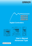
Model UT551
Digital Indicating Controller
with Active Color PV Display
GS 05D01C04-01E
■ General
Model UT551 Digital Indicating Controller is an intelligent,
micro-processor based digital indicating controller with
powerful control capability. It has a user-friendly large
numerical display with the PV display color changing
function "Active Color PV Display." The UT551 features as
standard many functions which are necessary for various
control applications, and all of these functions such as
control function, control computation function, signal
computation function, etc. can be configured by using the
keys on the front panel. The instrument has eight types of
control strategies and also an overshoot suppressing
function "SUPER" and a hunting suppressing function
"SUPER 2" as well as an auto-tuning function built in as
standard. It is suitable for a diverse range of applications,
with position-proportional control model and heating/
cooling control model also available.
■ Main Features
• Extra-large digital display allows the indicated values to be
read even from a long distance. LEDs of 20 mm height are
used for the PV display. This is a five-digit display for
higher resolution.
• Eight types of control function, including single-loop
control, cascade control, loop control with PV autoselector, and loop control with PV-hold function, enabling
the operator to start control operation immediately after
simply entering the settings.
• Parameters can easily be set using a personal computer.
("Parameter setting tool (model LL100)" sold separately is
required.)
• Universal input and output enables users to set or change
freely the type of PV inputs, PV input range, type of
control output, etc. from the front panel.
• In addition to standard type (universal output), the
position-proportional type (relay output) or the heating/
cooling type (universal output) can be specified.
• Contact inputs (up to 8 points) and contact outputs (up to 8
points) can be employed and functions can be assigned to each
contact. (The maximum number of points varies the suffix code.)
Note: See Hardware Specifications and Contact Outputs
described later.
• Various communication function are provided. Communication is possible with personal computer, programmable
logic controller, and other controllers.
■ Functional Specifications
● Control Functions
UT Mode
The following types of basic control structure can be set as
the UT mode by the user.
Single-loop control (UT mode 1):
The most simple and basic control function.
Cascade primary-loop control (UT mode 2):
Output tracking function and cascade control
logic are provided. Suitable for cascade
primary-loop control.
Cascade secondary-loop control (UT mode 3):
Setpoint output and cascade control logic are
provided. Suitable for cascade secondary-loop
control.
UT551
Indication in
green or red
color
UT551E
“E” indicates the model
with expanded functions.
Cascade control (UT mode 4):
Dual control function for cascade control is
available in a single instrument.
Loop control for back-up (UT mode 5):
Output tracking function is provided to back
up another control instrument. The local and
remote control outputs are switched by a
contact input.
Loop control with PV switching (UT mode 6):
Two PV inputs are switched for control
depending on the status of contact input or PV
input.
Loop control with PV auto-selector (UT mode 7):
Two PV inputs are automatically selected for
control with a high, low, average, or temperature-difference value selector.
Loop control with PV-hold function (UT mode 8):
This control holds a PV input and a control
output if an external sensor is switched.
● Control Computation Functions
In each UT mode, the following control computation
functions can be selected:
Continuous PID control, Time-proportional
PID control, Relay ON/OFF control, Positionproportional PID control (for UT551-1■,
UT551-4■)and Heating/Cooling control (for
UT551-1■).
Target setpoint and PID parameters:
Maximum eight sets of target setpoint and PID
parameters can be set. These eight sets can be
set for both the main and slave loops in
cascade control.
Zone PID selection:
The PV input range is divided into a maximum of seven zones with up to six reference
points, and PID parameters are selected for
every zone.
Zone PID selection (by target setpoint):
The setting range is divided into a maximum of
seven zones with up to six reference points, and
PID parameters are selected for every zone.
PID selection by external contact input:
PID No. 1 to 8 is selected by contact input.
GS 05D01C04-01E
© Copyright Mar. 2005 (YK)
1st Edition Mar. 2005 (YK)
2
<<Contents>> <<Index>>
Auto-tuning:
Available as standard. Possible to activate
auto-tuning for both main and slave loops for
cascade control.
"SUPER" function:
Overshoots generated by abrupt changes in the
target setpoint or by disturbances can be
suppressed.
"SUPER 2" function:
This function stabilizes the state of control
that is unstable due to hunting, etc. without
requiring any change in PID constants, when
the load and/or gain varies greatly, or when
there is a difference between the characteristics of temperature zones.
Preset output function:
When the instrument is in STOP mode, PV
input is burnt-out, or an abnormality is found
in an input circuit, a preset value is output as a
control output.
Sampling period
Each sampling period can be selected under
the following conditions:
50 ms:
Available for model code UT551-00, when
UT mode is set to Single-loop control and
the following functions are not used:
"SUPER" function, "SUPER 2" function,
heating/cooling control, PV input computation, setpoint rate-of-change limiter, MV
output rate-of-change limiter, deviation
alarm, sensor grounding alarm, fault
diagnosis alarm, and FAIL output.
100 ms:
Available when UT mode is not cascade
control.
200 ms:
Available when UT mode is cascade control.
(Set value when shipped from the factory: 200 ms)
500 ms:
Always available.
Operation Mode Switching
(Note: Communication enables all the following
mode switching to be executed.)
AUTO/MANUAL switching:
Bumpless/preset output value switching
between automatic operation mode and
manual control mode is available by using the
front keys or contact input. The contact input
has priority over front key input or switching
by communication. The contact input is
invalid for Cascade secondary-loop control or
Cascade control.
RUN/STOP switching:
Switching by contact input (bumpless for
switching from STOP to RUN). The contact
input has priority over switching by communication. In RUN mode, control computation is
activated. In STOP mode, control computation ceases and a preset value is output as a
control output while other functions operate
normally.
REMOTE/LOCAL switching:
Switching between remote setpoint and local
setpoint by instrument operation or contact
input. The contact input has priority over
instrument operation or switching by
communication. For remote to local switching, either bumpless tracking (employing the
remote setpoint on switching as the local
setpoint) or without tracking (directly
switching the local setpoint) can be specified.
CASCADE/AUTO/MANUAL switching:
Switching by instrument operation or contact
input. The contact input has priority over
instrument operation or switching by
communication. Valid for Cascade secondary-loop control or Cascade control.
All Rights Reserved. Copyright © 2005, Yokogawa Electric Corporation
Output tracking ON/OFF switching:
Provided for Cascade primary-loop control or
Loop control for backup. External tracking
signal and internal control output are switched
by the contact input. The contact input has
priority over the switching by communication.
Control Parameters Setting Range
Proportional band: 0.1 to 999.9%
0.0 to 999.9% (for heating/cooling PID
control), 0.0% available for ON/OFF control
Integral time: 1 to 6,000 s, or OFF (for Manual reset)
Derivative time: 1 to 6,000 s, or OFF
ON/OFF control hysteresis: 0.0 to 100.0% of PV input
range span
Preset output: -5.0 to 105.0% (0 mA or less cannot be
output)
Output limiter:
Setting range: -5.0 to 105.0% for both high
and low limits
However, "low limit setpoint < high limit
setpoint" must be satisfied.
In case of heating/cooling PID control, upper
limiter for heating and upper limiter for cooling.
Shutdown function:
When manual control is carried out with 4 to
20 mA output, control output can be output
down to about 0 mA (shutdown is specified
for -5.0% or less).
Rate-of-change limiter for output:
OFF or 0.1 to 100.0%/s
Deadband for heating/cooling control:
-100.0 to 50.0% for output value
Deadband for position-proportional control:
1.0 to 10.0% for output
● Configuration of Input/Output Signal
PV Input Computations
Input processing, Square root extraction (voltage input only,
Input low cut 0.0 to 5.0%), Ten-segment linearizer function,
Ten-segment bias, Bias addition (-100.0 to 100.0%), and
First order lag filter (OFF, time constant 1 to 120 s)
Auxiliary Input Computations
(Applied to remote setting input only)
Input processing, Square root extraction (Input low cut 0.0 to
5.0%), Bias addition (-100.0 to 100.0%), Ratio multiplication
(0.001 to 9.999), First order lag filter (OFF, time constant 1
to 120 s)
● Alarm Functions
Alarm types:
PV high limit, PV low limit, Deviation high
limit, Deviation low limit, De-energized on
deviation high limit, De-energized on
deviation low limit, Deviation high and low
limits, High and low limits within deviation,
De-energized on PV high limit, De-energized
on PV low limit, SP high limit, SP low limit,
Output high limit, Output low limit, Deviation
high limit for target setpoint, Deviation low
limit for target setpoint, De-energized on
deviation high limit alarm for target setpoint,
De-energized on deviation low limit alarm for
target setpoint, Deviation high and low limits
fot target setpoint, and Deviation within high
and low limits for target setpoint.
Alarm setting range:
PV/SP alarm: -100 to 100% of PV input range
Deviation alarm: -100 to 100% of PV input
range span
Output alarm: -5.0 to 105.0% of output value
Alarm hysteresis: 0.0 to 100.0% of PV input
range span
GS 05D01C04-01E
1st Edition Mar. 01, 2005-00
3
<<Contents>> <<Index>>
Delay timer:
0.00 to 99.59 (minute, second)
An alarm is output when the delay timer
expires after the alarm setpoint is reached.
Setting for each alarm is possible.
Stand-by action:
Stand-by action can be set to make PV/
deviation alarm OFF during start-up or after
SP change until SP reaches the normal region.
Timer function (stabilization of control status notification
event) (Alarm 1 only):
This function sets the alarm 1 output to ON
when a preset time (timer setting) elapses after
a PV has reached the control target setpoint
hysteresis band to notify that control has
reached its stabilized status. Restarted in
RUN/STOP or SP switching.
Other alarm actions:
Sensor grounding alarm: Detects sensor
deterioration and outputs an alarm.
Fault-diagnosis alarm: For input burnout, A/D
conversion error, or thermocouple reference
junction compensation error.
FAIL output: Abnormality in software or
hardware.
Number of alarm settings: 8 (maximum)
The alarm status can be read via communication in addition to output as the above alarm
output.
Alarm output points (see also the item "Contact Outputs")
• Number of contact (relay) outputs:
3 (standard) or 4 (if a control output relay is
used for the alarm 4 output relay.)
• Number of contact (transistor open collector)
outputs:
4 (when optional function code is specified
as 1 or 3)
From the above, up to 8 point outputs can be obtained
(except for cascade control).
Any of PV alarm, deviation alarm, SP alarm, output alarm,
Fault-diagnosis alarm, sensor grounding alarm and FAIL
output can be assigned to contacts for the above number of
outputs. However, the timer delay alarm can be assigned
to the alarm 1 output only. Also, the alarm 4 only can be
assigned to the control output relay (if a relay is not used
for control output).
● Display and Operation Functions
PV Display
PV is displayed in the 5-digit display. PV1 or PV2 is
displayed by switching them in cascade control. The number
of display digits is 4 or 5. For thermocouple or RTD, data
below the decimal point can be set not to display. The
display range is -19999 to 30000 and the display span is
30000 or less.
Setpoint Display
A parameter name is displayed in the 3-digit display and data
in the 5-digit display. There are four kinds of displays :
operating display, operating parameter setting display, setup
parameter setting display and SELECT display.
Operating display:
Data necessary for operations, such as setpoint
or control output, are displayed depending on
the UT mode.
Operating parameters setting display:
The Operating parameters, which are mainly
changed during operations, such as PID
constant, are displayed.
All Rights Reserved. Copyright © 2005, Yokogawa Electric Corporation
Setup parameters setting display:
The Setup parameters to configure the
functions of the instrument before starting
operation are displayed.
UT mode is to be set in this display.
SELECT display:
Up to five displays which are frequently
accessed can be selected from the Operating
parameters setting display and Setup parameters setting display to be displayed in the
SELECT display.
Status Indicator Lamps
Alarm indicator lamps:
Four lamps, AL1, AL2, AL3, and AL4
Status indicator lamps:
REM (remote operation), MAN (manual mode
operation), CAS (cascade operation), and LP2
(cascade secondary-loop control)
Deviation monitor:
▲Plus deviation, ▼Minus deviation, and
deviation in normal range
PV display color changing function “Active Color PV
Display”
(Factory-set default : Fixed in red mode)
This function automatically changes PV
display color by the action described below.
Green-to-red or red-to-green changing action
is selectable.
Link to alarm 1 mode :
Alarm OFF : green, Alarm ON : red
Setting of Alarm OFF : red, Alarm ON :
green is possible.
Link to alarm 1 and 2 mode :
Alarm OFF : green, Alarm ON : red
Setting of Alarm OFF : red, Alarm ON :
green is possible.
SP deviation mode :
Within the preset SP deviation : green,
Out of the preset SP deviation : red
Setting of within the preset SP deviation :
red,
Out of the preset SP deviation : green is
possible.
Deviation band is changeable using a
parameter. The setting of either high limit
deviation or low limit deviation is also
possible.
PV limit mode :
Within the preset PV range : green,
Out of the preset PV range : red
Setting of within the preset PV range : red,
Out of the preset PV range : green is
possible.
The range (high limit and low limit) is
changeable using a parameter.
Fixed color mode :
PV display color is fixed in green or red.
Operation Keys
䉭, 䉮 keys: Increase or decrease setpoints and other
parameters displayed in the setpoint display.
SET/ENT key: Used for setting or changing set data,
switching the displayed contents, and
switching operation modes except for A/M.
A/M key: Operation mode switching (Auto/Manual)
Security Function
Key-lock by parameter setting and prohibiting
operation by a password are available.
GS 05D01C04-01E
1st Edition Mar. 01, 2005-00
4
<<Contents>> <<Index>>
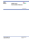
Examples of Communication System Configuration Diagram
(1) Personal computer link communication/
MODBUS communication
(2) Ladder communication
MELSEC-A
Personal computer
Programmable logic controllor
PV2
PV
PV2
PV
PV2
PV
PV2
PV
PV2
PV
PV2
PV
PV2
PV
PV
PV2
AL
AL
AL
AL
1
AL
AL
REM
MAN1
MAN2
STP
CAS
SET/ENT
AL
REM
MAN1
MAN2
STP
CAS
A/M
DISP
SET/ENT
AL
REM
MAN1
MAN2
STP
CAS
A/M
DISP
SET/ENT
REM
MAN1
MAN2
STP
CAS
REM
MAN1
MAN2
STP
CAS
A/M
A/M
DISP
REM
MAN1
MAN2
STP
CAS
A/M
DISP
SET/ENT
SET/ENT
UT551
Digital indicating controller
REM
MAN1
MAN2
STP
CAS
A/M
DISP
SET/ENT
REM
MAN1
MAN2
STP
CAS
A/M
DISP
SET/ENT
A/M
DISP
SET/ENT
DISP
UT551
Digital indicating controller
(3) Coordinated operation
PV2
PV
AL
REM
MAN1
MAN2
STP
CAS
A/M
SET/ENT
PV2
DISP
PV
UP750, UP550 Program controller or
UT750, UT550, UT520, UT551, UT450, and UT420
Digital indicating controller
PV2
AL
PV
PV2
AL
REM
MAN1
MAN2
STP
CAS
SET/ENT
PV2
SET/ENT
REM
MAN1
MAN2
STP
CAS
A/M
DISP
PV
AL
REM
MAN1
MAN2
STP
CAS
A/M
DISP
PV
AL
REM
MAN1
MAN2
STP
CAS
A/M
SET/ENT
A/M
DISP
SET/ENT
DISP
UT551
Digital indicating controller
● Communication Functions
(For optional function code ■1 or ■2 only)
This controller has four types of communication protocol
with one communication interface. Communication is
possible with personal computer, programmable logic
controller, and other controllers.
Communication Protocol
Computer link communication:
Communication protocol with a personal
computer
Ladder communication:
Communication protocol with the ladder
program on some programmable logic
controllers.
Coordinated operation:
Protocol for coordinated operation with more
than one GREEN Series controller. The
UT551 controller can be connected as a
master or slave station.
Status indicator lamps
Deviation (䉱, 䊏, 䉲)
Cascade operation (CAS), remote operation (REM)
and Manual operation (MAN)
Lit for secondary parameter indication (LP2)
Light-loader interface
Parameters are set via communication from a
personal computer.
Operation keys
Increase/decrease of the setting data (䉭, 䉮)
Screen switching/parameter selection/entry of set
data (SET/ENT)
Auto/manual operation mode switching (A/M)
All Rights Reserved. Copyright © 2005, Yokogawa Electric Corporation
MODBUS communication:
Communication protocol with a personal
computer, or PLC.
RS-485 Communication Interface
The RS-485 communication interface (conforms to EIA
RS485) can be used for personal computer link, MODBUS
communication, ladder communication, or for coordinated
operation.
Maximum number of connectable controllers:
31 GREEN Series controllers
Maximum communication distance: 1200 m
Communication method:
Two-wire half-duplex or four-wire halfduplex, start-stop synchronization, and nonprocedural
Baud rate:
600, 1200, 2400, 4800, or 9600 bps
Measured value (PV) display
Displays PV and error codes when
errors are detected.
Setpoint display
Displays setpoints (SP), output
values, valve opening, or
parameters.
Alarm indicator lamps
Displays alarms (AL1, AL2, AL3,
or AL4).
GS 05D01C04-01E
1st Edition Mar. 01, 2005-00
5
<<Contents>> <<Index>>
■ Hardware Specifications
Allowable signal source resistance:
250 Ω or less for TC or mV input
Signal source resistance effect
0.1 µV/Ω or less
2 kΩ or less for DC voltage input
Signal source resistance effect
About 0.01%/100 Ω
Allowable wiring resistance (for RTD input):
Maximum 150 Ω/wire (Conductor resistance
between three wires must be equal.)
However, it must be 10 Ω/wire for a
maximum range of -150.0 to 150.0°C.
Effect of wiring resistance: ±0.1°C/10Ω
Allowable input voltage:
±10 V DC for TC/mV/RTD input
±20 V DC for DC voltage input
Noise rejection ratio:
Normal mode 40 dB (50/60 Hz) or more
Common mode120 dB (50/60 Hz) or more
Reference junction compensation error:
±1.0°C (15 to 35°C), ±1.5°C (0 to 15°C and
35 to 50°C)
Applicable standards:
JIS, IEC, and DIN (ITS-90) for TC and RTD
● Input/Output Signal Specifications
PV Input Signal
Number of input points: 1
Input type, instrument input range, and measurement
accuracy:
The type of input and instrument input range
can be specified from the instrument input
range codes shown in the table below.
Sampling period: 50, 100, 200, or 500 ms (selectable)
Burnout detection:
Activated for thermocouple (TC) input, RTD
input, or standard signal of 0.4 to 2 V DC or 1
to 5 V DC.
Possible to specify a travel of upscale,
downscale, or off.
For standard signal input, set to burnout at
0.1 V or less.
Input bias current: 0.05 µA (for TC or RTD b-terminal)
Measurement current(RTD): About 0.13 mA
Input resistance: 1 MΩ or more for TC or mV input
About 1 MΩ for DC voltage input
Input Type
Unspecified (When shipped from the factory)
Thermocouple K
J
T
B
Instrument Input
Range Code
OFF
1
2
3
4
5
6
7
Instrument Input
Range (°C)
Instrument Input
Range (°F)
Set the data item PV input type “IN 1” to the OFF option to leave the PV input type undefined.
-270.0 to 1370.0°C
-270.0 to 1000.0°C
-200.0 to 500.0°C
-200.0 to 1200.0°C
-270.0 to 400.0°C
0.0 to 400.0°C
0.0 to 1800.0°C
-300.0 to 2300.0°F
-450.0 to 750.0°F
-200.0 to 750.0°F
32 to 3300°F
±0.1% ±1 digit of instrument range at 0°C or more
±0.2% ±1 digit of instrument range at less than 0°C
• However, ±2% ±1 digit of instrument range for type K
at temperatures less than -200°C.
• However, ±1% ± 1 digit of instrument range for type T
at temperatures less than -200°C.
±0.15% ±1 digit of instrument range at 400°C or more
±5% ±1 digit of instrument range at less than 400°C
8
9
10
0.0 to 1700.0°C
0.0 to 1700.0°C
-200.0 to 1300.0°C
32 to 3100°F
32 to 3100°F
-300.0 to 2400.0°F
±0.15% ± 1 digit of instrument range
E
L (DIN)
U (DIN)
11
12
13
14
-270.0 to 1000.0°C
-200.0 to 900.0°C
-200.0 to 400.0°C
0.0 to 400.0°C
-450.0 to 1800.0°F
-300.0 to 1600.0°F
-300.0 to 750.0°F
±0.1% ±1 digit of instrument range at 0°C or more
±0.2% ±1 digit of instrument range at less than 0°C
• However, ±1.5% ±1 digit of instrument range for
type E at temperature less than -200°C.
W (DIN)
15
16
-200.0 to 1000.0°F
32 to 4200°F
32.0 to 2500.0°F
±0.2% ±1 digit of instrument range
W97Re3-W75Re25
JPt100
17
18
30
0.0 to 2300.0°C
0.0 to 1390.0°C
0.0 to 1900.0°C
0.0 to 2000.0°C
31
-200.0 to 500.0°C
-150.00 to 150.00°C
Pt100
35
36
37
-200.0 to 850.0°C
-200.0 to 500.0°C
-150.00 to 150.00°C
Standard
signal
0.4 to 2V
40
41
0.400 to 2.000 V
1.000 to 5.000 V
0.000 to 2.000 V
DC voltage
0 to 10V
-10 to 20mV
0 to100mV
Note 1:
Note 2:
*1:
*2:
-450.0 to 2500.0°F
-450.0 to 2300.0°F
-200.0 to 1000.0°F
S
R
N
Platinel 2
PR20-40
RTD
Measurement Accuracy*1
1 to 5V
0 to 2V
50
51
55
0.00 to 10.00 V
-10.00 to 20.00 mV
56
0.0 to 100.0 mV
±0.1% ± 1 digit of instrument range
±0.25% ±1 digit of instrument range for
temperature at less than 0°C
±0.1% ± 1 digit of instrument range
±0.5% ±1 digit of instrument range at 800°C or more
Accuracy not guaranteed for temperature less than
800°C
32 to 3400°F
32 to 3600°F
-300.0 to 1000.0°F
-200.0 to 300.0°F
-300.0 to 1560.0°F
-300.0 to 1000.0°F
±0.2% ± 1 digit of instrument range
±0.1% ± 1 digit of instrument range (Note 1) (Note 2)
±0.2% ± 1 digit of instrument range (Note 1)
±0.1% ± 1 digit of instrument range (Note 1) (Note 2)
-200.0 to 300.0°F
±0.2% ± 1 digit of instrument range (Note 1)
Display range
-19999 to 30000
Display span 30000 or
less (Decimal point
position changeable)
±0.1% ± 1 digit of instrument range
The accuracy is ±0.3°C of instrument range ±1 digit for a temperature range from 0 to 100°C.
The accuracy is ±0.5°C of instrument range ±1 digit for a temperature range from -100 to 200°C.
Performance in the standard operating conditions (at 23±2°C, 55±10% RH, and 50/60Hz power frequency)
When receiving 4 to 20mA DC current signals, select a standard signal 1 to 5V DC and connect a 250 ohm resistor (option).
Model: X010-250-2 (resistor with M3.5 crimp-on terminal lugs)
All Rights Reserved. Copyright © 2005, Yokogawa Electric Corporation
GS 05D01C04-01E
1st Edition Mar. 01, 2005-00
6
<<Contents>> <<Index>>
Auxiliary Analog Input Signal
(UT551-■1, -■2, or -■4 only)
Functions: Remote setting input, tracking input, cascade
control secondary loop PV input, etc.
Input type: Settable within the range of voltage input 0 to
2 V DC, 0 to 10 V DC, 0.4 to 2.0 V DC or
1 to 5 V DC.
Number of inputs: 1 point
Sampling period: 100, 200 or 500 ms
Auxiliary analog input sampling period is
linked with PV input sampling period.
(If PV input period is 50 ms , auxiliary analog
input period is 100 ms.)
Input resistance: Approx. 1 MΩ
Input accuracy: ±0.3% ± 1 digit of input span for 0 to 2 V
DC input
±0.2% ± 1 digit of input span for 0 to 10 V
DC input
±0.375% ± 1 digit of input span for 0.4 to 2.0
V DC range
±0.3% ± 1 digit of input span for 1 to 5 V DC
range
Performance in the standard operating
conditions (at 23±2°C, 55±10% RH, and 50/
60Hz power frequency)
Feedback Resistance Input Signal
(UT551-1■ and -4■ only) Valid for position proportional
PID control.
Slidewire resistance:
Total resistance 100 Ω to 2.5 kΩ (with burnout detection of
slidewire)
Measuring resolution ±0.1% of total resistance
24 V DC Loop Power Supply for Sensor
(UT551-3■ and -4■ only)
Supplies power to the 2-wire transmitter. The current signal
is converted to a voltage signal by placing a resistor
(arbitrary from 10 to 250 Ω) and is read by the PV input
terminal.
21.6 to 28.0 V DC, maximum supply current about 30 mA
(only for models with 24 V DC loop power supply for sensor).
■24 V DC Power Supply Wiring to Two-wire Sensor
12
External
resistor 250Ω
(Note)
Two-wire transmitter
PV input
1 to 5 V DC signal
13
43
4-20mADC
Loop power
supply
21.6 to
28.0 V DC
44
Note : Connecting a 250Ω resistor to the terminals is optional.
Model : X010-250-2 (resistor with M3.5 crimp-on terminal lugs)
Retransmission Output
Any of the PV, target setpoint or control output is output.
Or this can be used for 15 V DC loop power supply.
Number of output points: 1 or 2
Retransmission output 2 is available only when
“relay” is selected as the control output type.
Output signal: 4 to 20 mA DC, 0 to 20 mA DC, 20 to 4
mA DC or 20 to 0 mA DC (0 mA or less
cannot be output)
All Rights Reserved. Copyright © 2005, Yokogawa Electric Corporation
Load resistance: 600 Ω or less
Output accuracy: ±0.1% of span (±5% for 1 mA or less)
Performance in the standard operating
conditions (at 23±2°C, 55±10% RH, and 50/
60Hz power frequency)
When using for 15 V DC loop power supply:
Supply voltage 14.5 to 18.0 V DC, maximum supply
current about 21 mA (with the protection circuit at field
short-circuit).
Control Outputs
Select 1 or 2 points (UT551-2■) from the following output
types depending on model type and UT mode. Relay contact
output for position proportional PID control (UT551-1■ and
UT551-4■).
Current output
Number of output points: 1 or 2 (for heating/cooling
type) (switchable to voltage pulse output)
Output signal: 4 to 20 mA DC, 0 to 20 mA DC, 20 to 4
mA DC or 20 to 0 mA DC
Load resistance: 600 Ω or less
Output accuracy:
±0.1% of span (±5% for 1 mA or less)
Performance in the standard operating
conditions (at 23±2°C, 55±10% RH, and 50/
60Hz power frequency)
Voltage pulse output
Number of output points: 1 or 2 (for heating/cooling
control) (switchable to current output)
Output signal:
ON voltage-12 V DC or more (load
resistance 600 Ω or more)
OFF voltage- 0.1 V DC or less
Resolution: 10 ms or 0.1% of output value, whichever is
greater
Relay contact output
Number of output points: 1 or 2 (for heating/cooling
control)
Output signal: At three terminals of NC, NO, and
Common
Contact rating: 250 V AC, 3 A or 30 V DC, 3 A
(resistance load)
Resolution: 10 ms or 0.1% of output value, whichever is
greater
Contact Inputs
Usage:
Target setpoint switching, C/A/M mode
switching, REMOTE/LOCAL switching,
RUN/STOP switching, or PV input switching
Number of input points:
Varies with optional function codes (as shown below):
UT551-■0: 2 points
UT551-■1: 8 points
UT551-■2: 3 points
UT551-■3: 7 points
UT551-■4: 3 points
Input type: Non-voltage contact input or transistor open
collector input
Input contact rating: 12 V DC, 10 mA or more
On/off detection:
For non-voltage contact input,
On .. contact resistance 1 kΩ or less;
Off.. contact resistance 20 kΩ or more
For transistor contact input,
On .. 2 V or less;
Off.. leak current 100 µA or less
Minimum status detection hold time: PV input sampling
period ×3
GS 05D01C04-01E
1st Edition Mar. 01, 2005-00
7
<<Contents>> <<Index>>
Contact Outputs
Usage:
Alarm output, FAIL output
Number of output points:
Varies with optional function codes (as shown below):
UT551-■0: Relay output 3 points
UT551-■1: Relay output 3 points, transistor output 4
points
UT551-■2: Relay output 3 points
UT551-■3: Relay output 3 points, transistor output 4
points
UT551-■4: Relay output 3 points
However, when a relay is not used for
control output, the relay for control output
can be used for the alarm 4. For this reason,
the number of relay output points can be
changed to 4 by adding to the above 3.
Relay contact rating: 240 V AC, 1 A or 30 V DC, 1 A,
normally open (COM terminal is comon for
every contact output)
(Normally close for FAIL output)
Transistor contact rating: 24 V DC, 50 mA
● Display Specifications
Measured value (PV) display:
5-digit 7-segment green or red color LED
display; height of letters 20 mm
Data display:
3 digits + 5 digits, 7-segment red color
LED display; height of letters 9.3 mm
Status indicator lamps: LEDs
● Conformance to Safety and EMC Standards
Safety: Complies with IEC/EN61010-1 (CE), approved by
C22.2 No.61010-1, approved by UL508.
Installation category : CAT. II Pollution
degree: 2 (IEC/EN61010-1, C22.2 No.61010-1)
Measurement category : I (CAT. I : IEC/
EN61010-1)
Rated measurement input voltage : 10V DC
max.(across terminals), 300V AC max.(across
ground)
Rated transient overvoltage : 1500V (Note)
Note : It is a value on the safety standard
which is assumed by IEC/EN61010-1 in
Measurement category I, and is not the value
which guarantees an apparatus performance.
EMC standards: Complies with EN61326, EN61000-3-2,
EN61000-3-3 and EN55011 (CE).
AS/NZS 2064 compliant (C-Tick).
Class A Group 1.
During test, the controller continues to operate
with the measurement accuracy within ±20%
of the range.
● Construction, Installation, and Wiring
Construction: Dust-proof and Drip-proof front panel
conforming to IP55.
For side-by-side close installation, the
controller loses its dust-proof and drip-proof
protection.
Material of the body: ABS resin and polycarbonate
Case color: Black
Weight:
About1 kg or less
External dimensions: 96W × 96H × 100D (from the panel
face) (mm)
Mounting: Direct panel mounting; mounting bracket, one
each for upper and lower mounting
All Rights Reserved. Copyright © 2005, Yokogawa Electric Corporation
W × 92 +0.8
H (mm)
Panel cutout dimensions: 92 +0.8
0
0
Mounting attitude:
Up to 30 degrees from horizontal; Must not
face downward.
Wiring connection:
With M3.5 screw terminals (for signal, power
and grounding wiring)
● Power Supply and Isolation
Power supply: Rated voltage 100 to 240 V AC (±10%),
50/60 Hz
Power consumption: Max. 20 VA (Max. 8.0 W)
Internal fuse rating: 250 V AC, 1.6 A time-lug fuse
Data backup: Non-volatile memory. Service life about
100,000 times of writings
Withstanding voltage:
1500 V AC for 1 min.
between primary terminals and secondary
terminals
1500 V AC for 1 min.
between primary terminals and ground
terminal
1500 V AC for 1 min.
between ground terminal and secondary
terminals
500 V AC for 1 min.
between secondary terminals
where primary terminals stand for power
and relay output terminals and secondary
terminals stand for analog input and output
signal terminals, voltage pulse output
terminals, and contact input terminals.
Isolation resistance:
20 MΩ or more for 500 V DC applied
between power terminals and ground terminal
Grounding: Class D grounding (grounding resistance of
100 Ω or less)
Isolation Specifications
PV input terminal:
Isolated from other input/output terminals, but
not isolated from internal circuit.
Auxiliary analog input terminal:
Isolated from other input/output terminals and
internal circuit.
15 V DC loop power supply terminal:
Not isolated from analog current output and
voltage pulse control output, but isolated from
other input/output terminals and internal
circuit.
24 V DC loop power supply terminal:
Isolated from 4-20mA analog ouptut, other
input/output terminals and internal circuit.
Control output (current output or voltage pulse output) and
retransmission output: Not isolated between
control output and retransmission output, but
isolated from other input/output terminals and
internal circuit.
Relay contact control output terminals:
Isolated between contact output terminals, and
from other input/output terminals and internal
circuit.
Contact input terminals:
Not isolated between contact input terminals
and from communication terminals, but
isolated from other input/output terminals and
internal circuit.
GS 05D01C04-01E
1st Edition Mar. 01, 2005-00
8
<<Contents>> <<Index>>
Relay contact output terminals:
Not isolated between relay contact outputs,
but isolated from other input/output terminals
and internal circuit.
Transistor contact output terminals:
Not isolated between transister contact
outputs, but isolated from other input/output
terminals and internal circuit.
RS-485 communication terminals:
Not isolated from contact input terminals, but
isolated from other input/output terminals and
internal circuit.
Feedback slidewire resistance input terminals:
Not isolated from control output terminals
(current or voltage pulse output) and
retransmmision output, but isolated from other
input/output terminals and internal circuit.
Power terminals:
Isolated from other input/output terminals and
internal circuit.
Ground terminal:
Isolated from other input/output terminals and
internal circuit.
● Environmental Conditions
Normal operating conditions:
Ambient temperature: 0 to 50°C (40°C or less for sideby-side close mounting )
Temperature change rate limit: 10°C/h or less
Ambient humidity: 20 to 90% RH (no condensation)
Magnetic field: 400 A/m or less
Continuous vibration (5 to 14 Hz):
Peak-to-peak amplitude 1.2 mm or less
Continuous vibration (14 to 150 Hz):
4.9 m/s2 or less
Short-period vibration: 14.7 m/s2, 15 s or less
Shock: 147 m/s2 or less, 11 ms
Installation altitude: 2000 m or less above sea level
Warm-up time: 30minutes or more after power on
Transportation and storage conditions:
Temperature: -25 to 70°C
Temperature change rate: 20°C/h or less
Humidity: 5 to 95% RH (no condensation)
Effects of operating conditions
Effect of ambient temperature:
Whichever is greater, ±1 µV/°C or ±0.01%
of F.S./°C for voltage or thermocouple
inputs.
±0.02% of F.S./°C for Auxiliary input
±0.05°C/°C (ambient temperature) or less
for RTD inputs.
±0.05% of F.S./°C or less for analog
outputs.
Effect of power supply fluctuation (within rated voltage
range):
Whichever is greater, ±1 µV/10 V or
±0.01% of F.S./10 V for analog inputs.
±0.05% of F.S./10 V or less for analog
outputs.
All Rights Reserved. Copyright © 2005, Yokogawa Electric Corporation
GS 05D01C04-01E
1st Edition Mar. 01, 2005-00
9
<<Contents>> <<Index>>
■ Function Block Diagram for Single-loop Control
(Model UT551-0■ ,UT551-2■ or UT551-3■)
(See the User’s Manual (Reference) (CD-ROM) for Function Block Diagrams for other modes.)
PV input terminals
11 , 12 and 13
Remote input
terminals 21 and 22
Communication
terminals 23 to 27
INPUT1
INPUT3
Input selection
Input selection
Unit selection
Unit selection
Analog input range conversion
Analog input range conversion
Contact input
RS485
Analog input bias
Analog input bias
Square root extraction
Square root extraction
Analog input filter
Analog input filter
DI3
DI4
DI5
DI6
DI1
DI2
DI8
Target
setpoint
selection
10-seg. linearizer approx./bias
Remote setting filter
PV input bias
Aux. Input
Communication
RMS=RSP
RMS=COM
SPN
PV input filter
Ratio/bias calculation
Target setpoints 1 to 8
REMOTE
R/L
LOCAL
REMOTE(ON)/LOCAL(OFF) switching
Target setpoint ramp-rate function
Manual operation
Control computation
MAN
A/M
AUTO
AUTO(ON)/MAN(OFF) switching
Preset output
24V loop power supply
Output limiter
STOP
RUN
S/R
STOP(ON)/RUN(OFF) switching
15V loop power supply
OT1
Control output
LPS
OUTPUT1
OUTPUT1
Alarm function
Retransmission output
RT2
RT1
OUTPUT1
OUTPUT3
Current*
terminals
16 and 17
Current
terminals
14 and 15
ON in
normal
condition
DO1
DO2
DO3
DO4
DO7
Alarm 1 Alarm 2 Alarm 3 Alarm 4 FAIL output
Terminals 43 and 44
Current or
pulse terminals
16 and 17
Relay terminals
1 , 2 and 3
* Unavailable when control output is current or pulse.
Terminal
Parameter
Function
Analog Signal
Contact Signal
Front Panel Key
Legend
All Rights Reserved. Copyright © 2005, Yokogawa Electric Corporation
GS 05D01C04-01E
1st Edition Mar. 01, 2005-00
10
<<Contents>> <<Index>>
■ Function Block Diagram for Single-loop Heating/Cooling Control (Model UT551-2■)
PV input terminals
11 , 12 and 13
Remote input
terminals 21 and 22
INPUT1
INPUT3
Input selection
Input selection
Communication
terminals 23 to 27
Contact input
RS485
Unit selection
Unit selection
Analog input range conversion
Analog input range conversion
Analog input bias
Analog input bias
Square root extraction
Square root extraction
Analog input filter
Analog input filter
DI3
DI4
DI5
DI6
DI1
DI2
DI8
Target
setpoint
selection
10-seg. linearizer approx./bias
Remote setting filter
Aux. Input
Communication
RMS=RSP
PV input bias
RMS=COM
SPN
PV input filter
Ratio/bias calculation
Target setpoints 1 to 8
REMOTE
LOCAL
R/L
REMOTE(ON)/LOCAL(OFF) switching
Target setpoint ramp-rate function
Manual operation
Control computation
MAN
A/M
AUTO
AUTO(ON)/MAN(OFF) switching
Heating/cooling computation
Heating-side output limiter
Cooling-side output limiter
Heating-side
preset output
Cooling-side
preset output
OT1
Cooling-side
output
Heating-side
output
OUTPUT1
Current or
pulse terminals
16 and 17
15V loop
power supply
OT1
OUTPUT1
OUTPUT2
Relay
Current or pulse
terminals
terminals
1 , 2 and 3
46 and 47
S/R
STOP(ON)/RUN(OFF) switching
Retransmission
output
Alarm function
ON in
normal
condition
RT2
RT1
OUTPUT2
OUTPUT1
OUTPUT3
Relay
terminals
48 , 49 and 50
Current*
terminals
16 and 17
Current
terminals
14 and 15
DO1
DO2
DO3
DO4
DO7
Alarm
1
Alarm
2
Alarm
3
Alarm
4
FAIL
output
* Unavailable when heating-side output is current output or pulse.
Terminal
Parameter
Function
Analog Signal
Contact Signal
Front Panel Key
Legend
All Rights Reserved. Copyright © 2005, Yokogawa Electric Corporation
GS 05D01C04-01E
1st Edition Mar. 01, 2005-00
11
<<Contents>> <<Index>>
■ Function Block Diagram for Single-loop Position-proportional Control
(Model UT551-1■ or UT551-4■)
PV input terminals
11 , 12 and 13
Remote input
terminals 21 and 22
INPUT1
INPUT3
Input selection
Input selection
Communication
terminals 23 to 27
RS485
Unit selection
Unit selection
Analog input range conversion
Analog input range conversion
Analog input bias
Analog input bias
Square root extraction
Square root extraction
Analog input filter
Analog input filter
Contact input
DI3
DI4
DI5
DI6
DI1
DI2
DI8
Target
setpoint
selection
10-seg. linearizer approx./bias
Remote setting filter
PV input bias
Aux. Input
Communication
RMS=RSP
RMS=COM
SPN
PV input filter
Ratio/bias calculation
REMOTE
R/L
In MAN operation, relay
is ON when
or
key is hold down.
Target setpoints 1 to 8
LOCAL
REMOTE(ON)/LOCAL(OFF) switching
Target setpoint ramp-rate function
Manual operation
Control computation
Output limiter
MAN
AUTO
A/M
AUTO(ON)/MAN(OFF) switching
Preset output
STOP
RUN
S/R
STOP(ON)/RUN(OFF) switching
Alarm function
Signal comparison
15V loop power supply Retransmission output
L relay
H relay
(
key)
(
key)
OUTPUT
terminals 48 ,
49 and 50
FEEDBACK
terminals 45 ,
46 and 47
Relay output
Direct/reverse signal
Feed-back input
M
ON in
normal
condition
RT2
RT1
OUTPUT1
OUTPUT3
OUTPUT1
terminals
16 and 17
OUTPUT3
terminals
14 and 15
DO1
DO2
DO3
DO4
DO7
Alarm
1
Alarm
2
Alarm
3
Alarm
4
FAIL
output
Motor-driven valve
Valve position
sliding resistor
Terminal
Parameter
Function
Analog Signal
Contact Signal
Front Panel Key
Legend
43
- 44 terminals : 24VDC loop power supply
All Rights Reserved. Copyright © 2005, Yokogawa Electric Corporation
GS 05D01C04-01E
1st Edition Mar. 01, 2005-00
12
<<Contents>> <<Index>>
■ Function Block Diagram for Cascade Control
Communication
terminals
23 to 27
Secondary PV
input terminals
21 and 22
INPUT1
RS485
INPUT3
Input selection
Ratio/bias
calculation
Input selection
Cascade primary PV
input terminals
11 , 12 and 13
Unit selection
Contact inputs
DI3
DI4
DI5
DI6
DI1
DI2
DI8
DI7
Manual
(OFF➝ON)
Cascade
(OFF➝ON)
Unit selection
Analog input range conversion
Analog input range conversion
Analog input bias
Analog input bias
Square root extraction
Square root extraction
Analog input filter
Analog input filter
10-seg. linearizer approx./bias
10-seg. linearizer approx./bias
PV input bias
PV input bias
PV input filter
PV input filter
Automatic
(OFF➝ON)
Target
setpoint
selection
SPN
RMS=COM
Primary target setpoint
R/L
REMOTE
LOCAL
If receives the FAIL signal
(burnout or A/D converter error)
from primary PV input, operation
is switched to AUTO.
Target setpoint ramp-rate function
SPN
Control computation 1
Secondary target setpoint
Output limiter
C/A/M
Tracking in
AUTO or MAN
CAS
AUTO, MAN
Cascade switching
Tracking signal
Manual operation
Control computation 2
MAN
Preset output
Output limiter
STOP
S/R
CAS, AUTO
C/A/M
MAN switching
A/M
RUN
STOP(ON)/RUN(OFF) switching
15V loop
power supply
Control
output
Retransmission
output
RT2
RT1
OUTPUT1
OUTPUT1
LPS
OUTPUT1
OUTPUT3
Current or pulse
terminals
16 and 17
Relay
terminals
1 , 2 and 3
Terminals
43 and 44
Current*1
terminals
16 and 17
Current
terminals
14 and 15
Alarm function
ON in normal
condition
24V loop
power supply
OT2
DO1
DO2
DO3
DO4
DO7
Alarm 1 Alarm 2 Alarm 3 Alarm 4 FAIL output
*1 Unavailable when control output is current or pulse.
Terminal
Parameter
Function
Analog Signal
Contact Signal
Front Panel Key
Legend
All Rights Reserved. Copyright © 2005, Yokogawa Electric Corporation
GS 05D01C04-01E
1st Edition Mar. 01, 2005-00
13
<<Contents>> <<Index>>
■ Function Block Diagram for Loop Control for Backup
Communication
Tracking signal
terminals
(Manipulated output from host)
23 to 27
terminals 21 and 22
INPUT1
RS485
INPUT3
Contact inputs
DI3
Input selection
Input selection
Unit selection
Unit selection
Analog input range conversion
Analog input range conversion
Analog input bias
Analog input bias
DI4
DI5
DI6
DI1
DI2
DI8
Tracking switching signal
PV input
terminals
11 , 12 and 13
Target
setpoint
selection
Square root extraction
Ratio/bias
calculation
Analog input filter
Analog input filter
10-seg. linearizer approx./bias
PV input bias
PV input filter
SPN
RMS=COM
Target setpoints
1 to 8
R/L
REMOTE
LOCAL
Target setpoint ramp-rate function
Manual operation
Control output
can not be
changed when
contact input 8 (DI8)
is set to ON.
Control computation
MAN
AUTO
A/M
AUTO(ON)/MAN(OFF) switching
Tracking (ON)
Output limiter
STOP
S/R
24V loop
power supply
RUN
STOP(ON)/RUN(OFF) switching
15V loop
Retransmission
power supply
output
OT1
Control
output
LPS
OUTPUT1
OUTPUT1
RT2
RT1
OUTPUT1
OUTPUT3
Alarm function
ON in normal
condition
Preset output
DO1
DO2
DO4
DO5
DO3
Alarm 1 Alarm 2 Alarm 4 Alarm 3 FAIL output
Terminals
43 and 44
Current or
pulse terminals
16 and 17
Relay
terminals
1 , 2 and 3
Current *1
terminals
16 and 17
Current
terminals
14 and 15
*1 Unavailable when control output is current or pulse.
Terminal
Parameter
Function
Analog Signal
Contact Signal
Front Panel Key
Legend
All Rights Reserved. Copyright © 2005, Yokogawa Electric Corporation
GS 05D01C04-01E
1st Edition Mar. 01, 2005-00
14
<<Contents>> <<Index>>
■ Function Block Diagram for Loop Control with PV Switching
PV input 2
terminals
21 and 22
PV input 1
terminals
11 , 12 and 13
Communication
terminals
23 to 27
INPUT1
INPUT3
RS485
Input selection
Input selection
Unit selection
Unit selection
Ratio/bias
calculation
Analog input range conversion
Analog input range conversion
Analog input bias
Analog input bias
DI3
Square root extraction
Analog input filter
Analog input filter
10-seg. linearizer approx./bias
10-seg. linearizer approx./bias
DI4
DI5
DI6
DI1
DI2
DI8
Target
setpoint
selection
PV input
switching
(U3=2)
Upper limit
Lower limit
Operation
U1
Square root extraction
Contact inputs
U2
U3
PV input Switching (Temp. range, Temp. upper limit, or DI)
Burnout occurs when
the burnout of PV
input 1 or PV input 2
occurs.
PV input bias
PV input 1(OFF)/
PV input 2(ON)
SPN
RMS=COM
PV input filter
Target setpoints 1 to 8
R/L
REMOTE
LOCAL
Target setpoint ramp-rate function
Control computation
MAN
A/M
Preset output
24V loop
power supply
AUTO
AUTO(ON)/MAN(OFF) switching
Output limiter
STOP
RUN
S/R
STOP(ON)/RUN(OFF) switching
15V loop
Retransmission
power supply
output
OT1
Control
output
RT2
RT1
OUTPUT3
LPS
OUTPUT1
OUTPUT1
OUTPUT1
Terminals
43 and 44
Current or
pulse terminals
16 and 17
Relay
terminals
1 , 2 and 3
Current *1
terminals
16 and 17
Alarm function
ON in normal
condition
Manual operation
DO1
DO2
DO3
DO4
DO7
Alarm 1 Alarm 2 Alarm 3 Alarm 4 FAIL output
Current
terminals
14 and 15
*1 Unavailable when control output is current or pulse.
Terminal
Parameter
Function
Analog Signal
Contact Signal
Front Panel Key
Legend
All Rights Reserved. Copyright © 2005, Yokogawa Electric Corporation
GS 05D01C04-01E
1st Edition Mar. 01, 2005-00
- 44
+ 43
3
NO
COM
All Rights Reserved. Copyright © 2005, Yokogawa Electric Corporation
10
9
8
RDA(-)
SG
26
27
49
50
9
10
Relay
GS 05D01C04-01E
DO4 34
DO5 33
Alarm 4 output
No function
COM 35
Relay contact rating: 240 V AC, 1 A
30 V DC, 1 A (resistance load)
Transistor contact rating: 24 V DC, 50 mA
Transistor
Common
FAIL output
DO7 31
(ON when normal)
DO6 32
COM 7
Common
No function
STOP when DI2=ON
RUN when DI2=OFF
DO3 4
Alarm 3 output
40
39
38
30
29
28
27
26
25
24
23
22
21
20
19
18
17
16
15
14
13
12
11
16 +
17 -
+5V
+5V
+5V
+5V
+5V
+5V
+5V
COM
DI8
COM
DI7
DI6
DI5
DI4
DI3
DI2
DI1
Contact rating: 12 V DC, 10 mA or more
COM 30
DI8 28
COM 20
DI7 36
DI6 37
DI5 38
DI4 39
DI3 40
DI2 18
External contact inputs
Contact +5V
UT
DI1 19
30
28
20
36
37
38
39
40
18
19
0-20mADC,
4-20mADC
Voltage pulse (12 V)
Transistor contact
12 +
13 -
0-20mADC,
4-20mADC
4-20 or
0-20 mA DC
15 -
14 +
14.5-18.0 V DC
(21 mA DC max.)
15 V DC loop power supply*
Default: 4-20 mA DC
15 -
14 +
Retransmission output 1*
13 -
12 +
mV/V input
13 B
12 b
250 Ω 4-20mA
* Retransmission output 1 is not available if a
15 V DC loop power supply is used.
Load resistance: 600 Ω or less
* Factory-set to “PV retransmission.”
Note: Connecting a 250 Ω resistor to the terminals is
optional.
Model: X010-250-2 (resistor with M3.5 crimp-on terminal
lugs)
13 -
12 +
set the PV input type to 1-5 V DC (setpoint “41”).
* When receiving 4-20 mA DC current signals,
䊏 Receiving 4-20 mA DC Current
Signals with the Controller
Time proportional control
Relay output
(terminals 1 , 2 and 3 )
OT1=0 (factory-set default)
Time proportional control
Voltage pulse output
(terminals 16 and 17 )
OT1=1
Current output
(terminals 16 and 17 )
OT1=2
Correspondence between parameter OT1 and control output types
On-off control
Relay output
(terminals 1 , 2 and 3 )
OT1=3
* OT1 is a setup parameter.
You can change the settings of the parameter OT1 to change the control output type.
Default: 4-20 mA DC
17 -
16 +
Default: Unspecified
retransmission type
Retransmission
output 2*
RTD input
11 A
Note: Select this option from the OT1 parameter.
* Retransmission output 2 is available
only when “relay” is selected as the
type of control output.
Current/voltage
pulse output
Control output
Default: 1-5 V DC
Specify in a range of
1-5 V DC, 0-2 V DC,
or 0-10 V DC.
TC input
PV input * Not configured at factory before shipment
Note: External Contact Input
If the power is turned on when the external contact input is OFF, the mode (SPN, R/L, or A/M)
existing before the power is turned off will be continued. (except for RUN/STOP)
Common
Remote when DI8=ON
Local when DI8=OFF
Common
No function
DI6 OFF OFF OFF OFF OFF OFF OFF ON
* If all of the contact inputs are set to OFF,
the controller uses the immediately
preceding target setpoint.
DI5 OFF OFF OFF ON ON ON ON OFF
DI3 ON OFF ON OFF ON OFF ON OFF
DI4 OFF ON ON OFF OFF ON ON OFF
1.SP2.SP 3.SP4.SP 5.SP6.SP7.SP 8.SP
When switching among target setpoints 1 to 8:
AUTO when DI1=ON
MAN when DI1=OFF
input registration parameter.
DO2 5
UT
48
8
37
36
35
34
33
32
31
22 -
21 +
* Wiring can only be carried out for
controllers with remote input.
Remote input
* The functionality of a contact input can be varied by changing the setting of the contact
47
7
46
6
44
45
4
5
43
42
41
3
2
1
Alarm 2 output
DO1 6
External contact outputs
Alarm 1 output
SDA(-)
25 RDB(+)
24
23 SDB(+)
for controllers with communication
functions.
Maximum baud rate: 9600 bps
RS-485 communication * Wiring can only be carried out
Before carrying out wiring, turn off the power
to the controller and check that cables to be
connected are not alive with a tester or the like
because there is a possibility of electric shock.
Allowable range: 100-240 V AC (10%)
(free voltage)
50/60 Hz shared
N
L
Power supply
Power supply
CAUTION
*Alarm 4 output is available only when
"current/voltage pulse" is selected as the
type of control output.
Note: Select this option from
the OT1 parameter.
*Time proportional PID relay contact
output is configured at factory
before shipment.
Contact rating: 250 V AC, 3 A
30 V DC, 3 A (resistance load)
1
2
NC
Relay contact output
Control output
21.6-28.0VDC
(30 mA DC max.)
*Wiring can only be carried out for controllers with
24 V DC loop power supply.
24 V DC loop
power supply
See the User’s Manual (Reference) (CD-ROM version) for the terminal arrangments not described in this document.
■ UT551 Single-loop Control (Model UT551-0■, UT551-2■or UT551-3■), Terminal Arrangements
<<Contents>> <<Index>>
15
1st Edition Mar. 01, 2005-00
UT
50
All Rights Reserved. Copyright © 2005, Yokogawa Electric Corporation
33
40
39
38
37
36
35
34
Relay
DO5 33
DO6 32
No function
No function
COM 35
GS 05D01C04-01E
Heating side: Voltage pulse output
(terminals 16 and 17 )
Cooling side: Relay output
(terminals 48 , 49 and 50 )
Heating side: Relay output
(terminals 1 , 2 and 3 )
Cooling side: Relay output
(terminals 48 , 49 and 50 )
30
29
28
27
26
25
24
23
22
21
20
19
18
17
16
15
14
13
12
11
22 -
16 +
17 -
1.SP2.SP 3.SP4.SP 5.SP6.SP7.SP 8.SP
0-20mADC,
4-20mADC
Voltage pulse (12 V)
+5V
+5V
+5V
+5V
DI2
COM
DI8
COM
DI7
DI6
DI5
DI4
DI3
Contact rating: 12 V DC, 10 mA or more
COM 30
DI8 28
COM 20
DI7 36
DI6 37
DI5 38
DI4 39
+5V
+5V
DI1
30
28
20
36
37
38
39
40
18
19
Transistor contact
0-20mADC,
4-20mADC
4-20 or
0-20 mA DC
15 -
14 +
14.5-18.0 V DC
(21 mA DC max.)
15 V DC loop power supply*
Default: 4-20 mA DC
15 -
14 +
Retransmission output 1*
13 -
12 +
mV/V input
13 B
12 b
OT1=7
Heating side: Relay output
(terminals 1 , 2 and 3 )
Cooling side: Voltage pulse output
(terminals 46 and 47 )
OT1=8
Heating side: Voltage pulse output
(terminals 16 and 17 )
Cooling side: Voltage pulse output
(terminals 46 and 47 )
䊏 Receiving 4-20 mA DC Current
Signals with the Controller
250 Ω 4-20mA
* Retransmission output 1 is not available if a
15 V DC loop power supply is used.
Load resistance: 600 Ω or less
* Factory-set to “PV retransmission.”
OT1=9
Heating side: Current output
(terminals 16 and 17 )
Cooling side: Voltage pulse output
(terminals 46 and 47 )
OT1=10
Heating side: Relay output
(terminals 1 , 2 and 3 )
Cooling side: Current output
(terminals 46 and 47 )
OT1=11
Heating side: Voltage pulse output
(terminals 16 and 17 )
Cooling side: Current output
(terminals 46 and 47 )
Heating side: Current output
(terminals 16 and 17 )
Cooling side: Current output
(terminals 46 and 47 )
OT1=12
Note: Connecting a 250 Ω resistor to the terminals is
optional.
Model: X010-250-2 (resistor with M3.5 crimp-on terminal
lugs)
13 -
12 +
set the PV input type to 1-5 V DC (setpoint “41”).
* When receiving 4-20 mA DC current signals,
Note: External Contact Input
If the power is turned on when the external contact input is OFF,
the mode (SPN, R/L, or A/M) existing before the power is turned
off will be continued. (except for RUN/STOP)
Default: 4-20 mA DC
17 -
16 +
Default: Unspecified
retransmission type
Retransmission
output 2*
RTD input
11 A
Correspondence between parameter OT1 and heating side output types/cooling side output types
Heating side: Current output
(terminals 16 and 17 )
Cooling side: Relay output
(terminals 48 , 49 and 50 )
OT1=6
Common
Remote when DI8=ON
Local when DI8=OFF
Common
No function
DI6 OFF OFF OFF OFF OFF OFF OFF ON
* If all of the contact inputs are set to OFF,
the controller uses the immediately
preceding target setpoint.
DI5 OFF OFF OFF ON ON ON ON OFF
DI3 ON OFF ON OFF ON OFF ON OFF
DI4 OFF ON ON OFF OFF ON ON OFF
DI3 40
DI2 18
+5V
External contact inputs
Contact +5V
UT
DI1 19
13 -
12 +
TC input
PV input * Not configured at factory before shipment
Note: Select this option from the OT1 parameter.
* Retransmission output 2 is available
only when “relay” is selected as the
type of control output.
Heating-side
control output
Current/voltage
pulse output
Default: 1-5 V DC
1-5 V DC, 0-2 V DC,
or 0-10 V DC.
The types of control output, “relay output” and “voltage pulse output” shown in the table above refer to those of time proportional control.
To change to a relay output for on-off control, select “Relay Terminals” and change the setpoint of the proportional band to “0.”
OT1=5
OT1=4 (factory-set default)
* OT1 is a setup parameter.
You can change the settings of the parameter OT1 to
change the control output type.
Relay contact rating: 240 V AC, 1 A
30 V DC, 1 A (resistance load)
Transistor contact rating: 24 V DC, 50 mA
Transistor
Common
FAIL output
DO7 31
(ON when normal)
DO4 34
Common
Alarm 4 output
When switching among target setpoints 1 to 8:
STOP when DI2=ON
RUN when DI2=OFF
DO3 4
Alarm 3 output
COM 7
AUTO when DI1=ON
MAN when DI1=OFF
input registration parameter.
DO2 5
DO1 6
31
32
Alarm 2 output
Alarm 1 output
External contact outputs
SG
* The functionality of a contact input can be varied by changing the setting of the contact
49
9
10
48
47
46
9
8
7
6
45
43
44
3
4
5
41
42
1
2
27
10
8
CAUTION
Before carrying out wiring, turn off the power
to the controller and check that cables to be
connected are not alive with a tester or the like
because there is a possibility of electric shock.
Allowable range: 100-240 V AC (10%)
(free voltage)
50/60 Hz shared
N
L
Power supply
Power supply
Contact rating: 250 V AC, 3 A
30 V DC, 3 A (resistance load)
Heating-side control output
*Alarm 4 output is
Relay contact output Note: Select this option from the
OT1 parameter.
available only when
1
*Time proportional PID relay contact
"current/voltage pulse" NC
output is configured at factory
is selected as the type
2
before shipment.
of heating-side control NO
output.
COM
3
Contact rating: 250 V AC, 3 A
30 V DC, 3 A (resistance load)
Cooling-side control Cooling-side control
RS-485 communication * Wiring can only be carried out for controllers
with communication functions.
output
output
Note: Select this option from
Maximum baud rate: 9600 bps
*Alarm 3 output is
the OT1 parameter.
Current/voltage pulse output Relay contact output
SDB(+)
23
available only when
*Time proportional PID
* Wiring can only be carried out for
NC
48
"current/voltage pulse"
relay contact output is
controllers with remote input.
24 SDA(-)
+ 46
is selected as the type
configured
at
factory
0-20 mA DC
Remote input
NO
49
4-20 mA DC,
of cooling-side control
before shipment.
25 RDB(+)
voltage pulse (12 V)
output.
- 47
COM
50
21 +
26 RDA(-)
Specify in a range of
■ UT551 Single-loop Heating/Cooling Control (Model UT551-2■), Terminal Arrangements
<<Contents>> <<Index>>
16
1st Edition Mar. 01, 2005-00
- 44
45
50
COM
All Rights Reserved. Copyright © 2005, Yokogawa Electric Corporation
10
9
8
CAUTION
42
46
6
49
50
9
10
40
39
38
37
36
35
34
33
32
31
Relay
COM 7
DO4 34
DO5 33
DO6 32
Common
Alarm 4 output
No function
No function
GS 05D01C04-01E
COM 35
Relay contact rating: 240 V AC, 1 A
30 V DC, 1 A (resistance load)
Transistor contact rating: 24 V DC, 50 mA
Transistor
Common
20
19
18
17
16
15
14
13
12
11
0-20mADC,
4-20mADC
Default: 4-20 mA DC
17 -
16 +
Default: Unspecified
retransmission type
Retransmission
output 2
Default: 1-5 V DC
Specify in a range of
1-5 V DC, 0-2 V DC,
or 0-10 V DC.
+5V
+5V
+5V
+5V
+5V
+5V
COM
DI8
COM
DI7
DI6
DI5
DI4
DI3
DI2
DI1
Contact rating: 12 V DC, 10 mA or more
COM 30
DI8 28
COM 20
DI7 36
DI6 37
DI5 38
DI4 39
DI3 40
DI2 18
+5V
External contact inputs
Contact +5V
UT
DI1 19
30
28
20
36
37
38
39
40
18
19
Transistor contact
13 -
12 +
TC input
䊏 Receiving 4-20 mA DC Current
Signals with the Controller
250 Ω 4-20mA
Note: Connecting a 250 Ω resistor to the terminals is
optional.
Model: X010-250-2 (resistor with M3.5 crimp-on terminal
lugs)
13 -
12 +
set the PV input type to 1-5 V DC (setpoint “41”).
* When receiving 4-20 mA DC current signals,
4-20 mA DC,
0-20 mA DC
15 -
14 +
* If 15 V DC loop power supply is used,
retransmission output 1 cannot be used.
Load resistance: 600 Ω or less
before shipment.
4-20mADC
44
43
13
12
Loop power
supply
21.628.0 V DC
PV input
1-5 V DC
signal
Note: Connecting a 250 resistor to the terminals is optional.
Model: X010-250-2 (resistor with M3.5 crimp-on terminal lugs)
Two-wire
transmitter
External
resistor 250
(Note)
䊏 24 V DC Power Supply Wired to Sensor in
Two-wire System Configuration
* The following method of wiring is only possible when the
controller is equipped with a 24 V DC loop power supply.
14.5-18.0VDC
(21 mA DC max.)
15 V DC loop power supply
Default: 4-20 mA DC
15 -
14 +
Retransmission output 1 * PV retransmission is configured at factory
13 -
12 +
mV/V input
13 B
12 b
11 A
RTD input
PV input * Not configured at factory before shipment
Note: External Contact Input
If the power is turned on when the external contact input is OFF, the mode (SPN, R/L, or A/M)
existing before the power is turned off will be continued. (except for RUN/STOP)
Common
Remote when DI8=ON
Local when DI8=OFF
Common
No function
DI6 OFF OFF OFF OFF OFF OFF OFF ON
* If all of the contact inputs are set to OFF,
the controller uses the immediately
preceding target setpoint.
DI5 OFF OFF OFF ON ON ON ON OFF
DI3 ON OFF ON OFF ON OFF ON OFF
DI4 OFF ON ON OFF OFF ON ON OFF
1.SP2.SP 3.SP4.SP 5.SP6.SP7.SP 8.SP
When switching among target setpoints 1 to 8:
STOP when DI2=ON
RUN when DI2=OFF
DO3 4
Alarm 3 output
input registration parameter.
AUTO when DI1=ON
MAN when DI1=OFF
FAIL output
DO7 31
(ON when normal)
30
29
28
27
26
25
24
23
22
21
22 -
21 +
Remote input
* The functionality of a contact input can be varied by changing the setting of the contact
48
8
47
45
5
7
44
4
43
2
3
41
SG
RDA(-)
1
27
26
DO2 5
DO1 6
SDA(-)
25 RDB(+)
24
23 SDB(+)
for controllers with communication
functions.
Maximum baud rate: 9600 bps
* Wiring can only be carried out for
controllers with remote input.
RS-485 communication * Wiring can only be carried out
Alarm 2 output
Alarm 1 output
External contact outputs
UT
Before carrying out wiring, turn off the power
to the controller and check that cables to be
connected are not alive with a tester or the like
because there is a possibility of electric shock.
Allowable range: 100-240 V AC (10%)
(free voltage)
50/60 Hz shared
N
L
Power supply
Power supply
Contact rating: 250 V AC, 3 A Resistance: 100 to 2.5 k
30 V DC, 3 A (resistance load)
100%
49
L
(Reverse)
47
46
48
0%
Feedback input
H
(Direct)
Relay contact output
Position proportional control output
21.6-28.0VDC
(30 mA DC max.)
+ 43
*Wiring can only be carried out for controllers with 24 V
DC loop power supply.
24 V DC loop
power supply
■ UT551 Single-loop Position Proportional Control (Model UT551-1■ or UT551-4■), Terminal Arrangements
<<Contents>> <<Index>>
17
1st Edition Mar. 01, 2005-00
- 44
+ 43
2
3
NO
COM
All Rights Reserved. Copyright © 2005, Yokogawa Electric Corporation
10
9
8
Relay
GS 05D01C04-01E
DO5 33
DO6 32
No function
No function
Common
COM 35
Relay contact rating: 240 V AC, 1 A
30 V DC, 1 A (resistance load)
Transistor contact rating: 24 V DC, 50 mA
Transistor
FAIL output
DO7 31
(ON when normal)
DO4 34
Common
DO3 4
Alarm 3 output
Alarm 4 output
DO2 5
Alarm 2 output
COM 7
DO1 6
External contact outputs
changing the setting of the contact output registration
parameter.
* The functionality of a contact output can be varied by
Alarm 1 output
SDA(-)
RDA(-)
SG
26
27
25 RDB(+)
24
23 SDB(+)
UT
48
49
50
8
9
10
40
39
38
37
36
35
34
33
32
31
30
29
28
27
26
25
24
23
22
21
20
19
18
17
16
15
14
13
12
11
22 -
21 +
17 -
16 +
0-20mADC,
4-20mADC
Voltage pulse (12 V)
+5V
+5V
+5V
+5V
+5V
+5V
+5V
COM
DI8
COM
DI7
DI6
DI5
DI4
DI3
DI2
DI1
Contact rating: 12 V DC, 10 mA or more
COM 30
DI8 28
COM 20
DI7 36
DI6 37
DI5 38
DI4 39
DI3 40
DI2 18
External contact inputs
Contact +5V
UT
DI1 19
30
28
20
36
37
38
39
40
18
19
Transistor contact
0-20mADC,
4-20mADC
4-20 or
0-20 mA DC
15 -
14 +
14.5-18.0 V DC
(21 mA DC max.)
15 V DC loop power supply*
Default: 4-20 mA DC
15 -
14 +
Retransmission output 1*
13 -
12 +
mV/V input
13 B
12 b
䊏 Receiving 4-20 mA DC Current
Signals with the Controller
250 Ω 4-20mA
* Retransmission output 1 is not available if a
15 V DC loop power supply is used.
Load resistance: 600 Ω or less
* Factory-set to “PV retransmission.”
Note: Connecting a 250 Ω resistor to the terminals is
optional.
Model: X010-250-2 (resistor with M3.5 crimp-on terminal
lugs)
13 -
12 +
set the PV input type to 1-5 V DC (setpoint “41”).
* When receiving 4-20 mA DC current signals,
Time proportional control
Relay output
(terminals 1 , 2 and 3 )
OT2=0 (factory-set default)
Time proportional control
Voltage pulse output
(terminals 16 and 17 )
OT2=1
Current output
(terminals 16 and 17 )
OT2=2
Correspondence between parameter OT2 and control output types
On-off control
Relay output
(terminals 1 , 2 and 3 )
OT2=3
* OT2 is a setup parameter.
You can change the settings of the parameter OT2 to change the control output type.
Default: 4-20 mA DC
17 -
16 +
Default: Unspecified
retransmission type
Retransmission
output 2*
RTD input
11 A
Note: External Contact Input
If the power is turned on when the external contact input (either of Cascade, Automatic, and Manual) is ON,
the controller judges that the external contact input is changed to ON.
Common
Manual switching when
DI8 changes to on
Common
STOP when DI7=ON
RUN when DI7=OFF
DI6 OFF OFF OFF OFF OFF OFF OFF ON
* If all of the contact inputs are set to OFF,
the controller uses the immediately
preceding target setpoint.
DI5 OFF OFF OFF ON ON ON ON OFF
DI3 ON OFF ON OFF ON OFF ON OFF
DI4 OFF ON ON OFF OFF ON ON OFF
1.SP2.SP 3.SP4.SP 5.SP6.SP7.SP 8.SP
When switching among target setpoints 1 to 8:
Automatic switching when
DI2 changes to on
Cascade switching when
DI1 changes to on
input registration parameter.
13 -
12 +
TC input
Primary PV input
* Not configured at factory before shipment
Note: Select this option from the OT2 parameter.
* Retransmission output 2 is available
only when “relay” is selected as the
type of control output.
Current/voltage
pulse output
Control output
Default: 1-5 V DC
Specify in a range of
1-5 V DC, 0-2 V DC,
or 0-10 V DC.
Auxiliary input
Secondary PV input
* The functionality of a contact input can be varied by changing the setting of the contact
47
46
6
7
45
44
43
42
41
5
4
3
2
1
for controllers with communication
functions.
Maximum baud rate: 9600 bps
RS-485 communication * Wiring can only be carried out
Before carrying out wiring, turn off the power
to the controller and check that cables to be
connected are not alive with a tester or the like
because there is a possibility of electric shock.
Allowable range: 100-240 V AC (10%)
(free voltage)
50/60 Hz shared
N
L
Power supply
Power supply
CAUTION
Note: Select this option from
the OT2 parameter.
*Time proportional PID relay contact
output is configured at factory
before shipment.
Contact rating: 250 V AC, 3 A
30 V DC, 3 A (resistance load)
1
NC
Relay contact output
Control output
21.6-28.0VDC
(30 mA DC max.)
*Wiring can only be carried out for controllers with
24 V DC loop power supply.
24 V DC loop
power supply
■ UT551 Cascade Control, Terminal Arrangements
<<Contents>> <<Index>>
18
1st Edition Mar. 01, 2005-00
- 44
+ 43
2
3
NO
COM
All Rights Reserved. Copyright © 2005, Yokogawa Electric Corporation
10
9
8
DO2 5
Alarm 2 output
Relay
GS 05D01C04-01E
Transistor
DO4 34
DO5 33
DO6 32
DO7 31
COM 35
Common
Alarm 4 output
Alarm 3 output
No function
No function
Common
Relay contact rating: 240 V AC, 1 A
30 V DC, 1 A (resistance load)
Transistor contact rating: 24 V DC, 50 mA
COM 7
FAIL output
DO3 4
(ON when normal)
DO1 6
External contact outputs
Alarm 1 output
SDA(-)
RDA(-)
SG
26
27
25 RDB(+)
24
23 SDB(+)
UT
1
41
49
50
9
10
31
40
39
38
37
36
35
34
33
32
30
29
28
27
26
25
24
23
22
21
11
20
19
18
17
16
15
14
13
12
22 -
21 +
17 -
16 +
0-20mADC,
4-20mADC
Voltage pulse (12 V)
+5V
+5V
+5V
+5V
+5V
+5V
+5V
COM
DI8
COM
DI7
DI6
DI5
DI4
DI3
DI2
DI1
Contact rating: 12 V DC, 10 mA or more
COM 30
DI8 28
COM 20
DI7 36
DI6 37
DI5 38
DI4 39
DI3 40
DI2 18
External contact inputs
Contact +5V
UT
DI1 19
30
28
20
36
37
38
39
40
18
19
Transistor contact
0-20mADC,
4-20mADC
RTD input
4-20 or
0-20 mA DC
15 -
14 +
14.5-18.0 V DC
(21 mA DC max.)
15 V DC loop power supply*
Default: 4-20 mA DC
15 -
14 +
Retransmission output 1*
13 -
12 +
mV/V input
13 B
12 b
11 A
䊏 Receiving 4-20 mA DC Current
Signals with the Controller
250 Ω 4-20mA
* Retransmission output 1 is not available if a
15 V DC loop power supply is used.
Load resistance: 600 Ω or less
* Factory-set to “PV retransmission.”
Note: Connecting a 250 Ω resistor to the terminals is
optional.
Model: X010-250-2 (resistor with M3.5 crimp-on terminal
lugs)
13 -
12 +
set the PV input type to 1-5 V DC (setpoint “41”).
* When receiving 4-20 mA DC current signals,
Time proportional control
Relay output
(terminals 1 , 2 and 3 )
OT1=0 (factory-set default)
Time proportional control
Voltage pulse output
(terminals 16 and 17 )
OT1=1
Current output
(terminals 16 and 17 )
OT1=2
Correspondence between parameter OT1 and control output types
On-off control
Relay output
(terminals 1 , 2 and 3 )
OT1=3
* OT1 is a setup parameter.
You can change the settings of the parameter OT1 to change the control output type.
Default: 4-20 mA DC
17 -
16 +
Default: Unspecified
retransmission type
Retransmission
output 2*
Note: External Contact Input
If the power is turned on when the external contact input is OFF, the mode (SPN, R/L, or A/M)
existing before the power is turned off will be continued. (except for RUN/STOP)
Common
Output of tracking signal when DI8=ON
Output of PID computation when DI8=OFF
Common
No function
DI6 OFF OFF OFF OFF OFF OFF OFF ON
* If all of the contact inputs are set to OFF,
the controller uses the immediately
preceding target setpoint.
DI5 OFF OFF OFF ON ON ON ON OFF
DI3 ON OFF ON OFF ON OFF ON OFF
DI4 OFF ON ON OFF OFF ON ON OFF
1.SP2.SP 3.SP4.SP 5.SP6.SP7.SP 8.SP
When switching among target setpoints 1 to 8:
STOP when DI2=ON
RUN when DI2=OFF
AUTO when DI1=ON
MAN when DI1=OFF
input registration parameter.
13 -
12 +
TC input
PV input * Not configured at factory before shipment
Note: Select this option from the OT1 parameter.
* Retransmission output 2 is available
only when “relay” is selected as the
type of control output.
Current/voltage
pulse output
Control output
Default: 1-5 V DC
Specify in a range of
1-5 V DC, 0-2 V DC,
or 0-10 V DC.
* The functionality of a contact input can be varied by changing the setting of the contact
48
8
46
47
6
7
45
44
43
42
5
4
3
2
Tracking Signal
for controllers with communication (host device operation output)
functions.
Auxiliary input
Maximum baud rate: 9600 bps
RS-485 communication * Wiring can only be carried out
Before carrying out wiring, turn off the power
to the controller and check that cables to be
connected are not alive with a tester or the like
because there is a possibility of electric shock.
Allowable range: 100-240 V AC (10%)
(free voltage)
50/60 Hz shared
* The functionality of a contact output can be varied by
changing the setting of the contact output registration
parameter.
N
L
Power supply
Power supply
CAUTION
Note: Select this option from
the OT1 parameter.
*Time proportional PID relay contact
output is configured at factory
before shipment.
Contact rating: 250 V AC, 3 A
30 V DC, 3 A (resistance load)
1
NC
Relay contact output
Control output
21.6-28.0VDC
(30 mA DC max.)
*Wiring can only be carried out for controllers with
24 V DC loop power supply.
24 V DC loop
power supply
■ UT551 Loop Control for Backup, Terminal Arrangements
<<Contents>> <<Index>>
19
1st Edition Mar. 01, 2005-00
- 44
+ 43
3
COM
All Rights Reserved. Copyright © 2005, Yokogawa Electric Corporation
10
9
8
SDA(-)
RDA(-)
SG
26
27
25 RDB(+)
24
23 SDB(+)
Relay
GS 05D01C04-01E
Common
COM 7
DO4 34
DO5 33
DO6 32
Common
Alarm 4 output
No function
No function
Common
COM 35
Relay contact rating: 240 V AC, 1 A
30 V DC, 1 A (resistance load)
Transistor contact rating: 24 V DC, 50 mA
Transistor
FAIL output
DO7 31
(ON when normal)
No function
DO3 4
Alarm 3 output
39
40
30
29
28
27
26
25
24
23
22
21
20
19
18
17
16
15
14
13
12
11
COM 30
DI8 28
COM 20
DI7 36
DI6 37
DI5 38
DI4 39
DI3 40
DI2 18
+5V
+5V
+5V
+5V
+5V
+5V
+5V
DI7
DI6
DI5
DI4
DI3
DI2
DI1
COM
DI8
COM
External contact inputs
Contact +5V
UT
DI1 19
16 +
17 -
30
28
20
36
37
38
39
40
18
19
0-20mADC,
4-20mADC
Voltage pulse (12 V)
Transistor contact
13 -
12 +
0-20mADC,
4-20mADC
4-20 or
0-20 mA DC
15 -
14 +
14.5-18.0 V DC
(21 mA DC max.)
15 V DC loop power supply*
Default: 4-20 mA DC
15 -
14 +
Retransmission output 1*
13 -
12 +
mV/V input
13 B
12 b
250 Ω 4-20mA
* Retransmission output 1 is not available if a
15 V DC loop power supply is used.
Load resistance: 600 Ω or less
* Factory-set to “PV retransmission.”
Note: Connecting a 250 Ω resistor to the terminals is
optional.
Model: X010-250-2 (resistor with M3.5 crimp-on terminal
lugs)
13 -
12 +
set the PV input type to 1-5 V DC (setpoint “41”).
* When receiving 4-20 mA DC current signals,
䊏 Receiving 4-20 mA DC Current
Signals with the Controller
Time proportional control
Relay output
(terminals 1 , 2 and 3 )
OT1=0 (factory-set default)
Time proportional control
Voltage pulse output
(terminals 16 and 17 )
OT1=1
Current output
(terminals 16 and 17 )
OT1=2
Correspondence between parameter OT1 and control output types
On-off control
Relay output
(terminals 1 , 2 and 3 )
OT1=3
* OT1 is a setup parameter.
You can change the settings of the parameter OT1 to change the control output type.
Default: 4-20 mA DC
17 -
16 +
Default: Unspecified
retransmission type
Retransmission
output 2*
RTD input
11 A
Note: Select this option from the OT1 parameter.
* Retransmission output 2 is available
only when “relay” is selected as the
type of control output.
Current/voltage
pulse output
Control output
Default: 1-5 V DC
Specify in a range of
1-5 V DC, 0-2 V DC,
or 0-10 V DC.
TC input
PV input 1 * Not configured at factory before shipment
Note: External Contact Input
If the power is turned on when the external contact input is OFF, the mode (SPN, R/L, or A/M)
existing before the power is turned off will be continued. (except for RUN/STOP)
Contact rating: 12 V DC, 10 mA or more
NOTE 1: When operating paramter U3 set to "2", effective to contact input.
Common
PV input 2 when DI8=ON
PV input 1 when DI8=OFF
(NOTE 1)
DI6 OFF OFF OFF OFF OFF OFF OFF ON
* If all of the contact inputs are set to OFF,
the controller uses the immediately
preceding target setpoint.
DI5 OFF OFF OFF ON ON ON ON OFF
DI3 ON OFF ON OFF ON OFF ON OFF
DI4 OFF ON ON OFF OFF ON ON OFF
1.SP2.SP 3.SP4.SP 5.SP6.SP7.SP 8.SP
When switching among target setpoints 1 to 8:
STOP when DI2=ON
RUN when DI2=OFF
DO2 5
Alarm 2 output
AUTO when DI1=ON
MAN when DI1=OFF
input registration parameter.
DO1 6
UT
49
50
9
10
38
37
36
35
34
33
32
31
22 -
21 +
Auxiliary input
PV input 2
* The functionality of a contact input can be varied by changing the setting of the contact
48
8
Alarm 1 output
External contact outputs
changing the setting of the contact output registration
parameter.
* The functionality of a contact output can be varied by
47
7
46
6
44
45
5
4
42
43
2
3
41
1
for controllers with communication
functions.
Maximum baud rate: 9600 bps
RS-485 communication * Wiring can only be carried out
Before carrying out wiring, turn off the power
to the controller and check that cables to be
connected are not alive with a tester or the like
because there is a possibility of electric shock.
Allowable range: 100-240 V AC (10%)
(free voltage)
50/60 Hz shared
N
L
Power supply
Power supply
CAUTION
Note: Select this option from
the OT1 parameter.
*Time proportional PID relay contact
output is configured at factory
before shipment.
Contact rating: 250 V AC, 3 A
30 V DC, 3 A (resistance load)
1
2
NC
NO
Relay contact output
Control output
21.6-28.0VDC
(30 mA DC max.)
*Wiring can only be carried out for controllers with
24 V DC loop power supply.
24 V DC loop
power supply
■ UT551 Loop Control with PV Switching, Terminal Arrangements
<<Contents>> <<Index>>
20
1st Edition Mar. 01, 2005-00
21
<<Contents>> <<Index>>
■ External Dimensions and Panel Cutout Dimensions
Unit: mm
11
96
100
Large bracket
AL1
2
3
4
112
LP2
96
CAS
REM
MAN
91.8
PV
A/M
SET/ENT
Small bracket
1 to 10 mm (Panel thickness)
General installation
Side-by-side close installation
[(N-1)96+92]
+0.8
0
92
+0.8
0
117 min.
145 min.
(53)
92
“N” stands for the number of controllers to be
installed.
However, the measured value applies if N 5.
+0.8
0
92
+0.8
0
(25)
All Rights Reserved. Copyright © 2005, Yokogawa Electric Corporation
GS 05D01C04-01E
1st Edition Mar. 01, 2005-00
22
<<Contents>> <<Index>>
■ Model and Suffix Codes
Model
Suffix Code
Description
Digital indicating controller (provided with retransmission output and 15 V DC loop power supply as standard)
UT551
-0
-1
-2
-3
-4
Type
Standard type
Position proportional type
Heating/cooling type
Standard type (with 24 V DC loop power supply)
Position proportional type (with 24 V DC loop power supply)
0
1
2
3
4
Optional functions
None
With communication, auxiliary analog (remote) input, 6 additional DIs and 4 additional DOs
With communication, auxiliary analog (remote) input, and 1 additional DI
With 5 additional DIs and 4 additional DOs
With auxiliary analog (remote) input and 1 additional DI
Standard accessories: Brackets (mounting hardware), unit label, User’s Manuals, and User’s Manual (reference) (CD-ROM
version).
Specify the required Suffix codes according to the UT mode to be used.
Correspondence between UT mode and suffix code
UT mode
Suffix code 00, 03, 01, 02, 10, 13, 11, 12, 21, 22,
20, 23, 04,
40, 43 14,
24
30, 33 31, 32,
41, 42,
34
44
Single-loop control
(UT mode 1) Cond. App. Cond. App.
Cascade primary loop control
(UT mode 2)
N/A
App.
N/A
N/A
Cond. Cond.: UT mode 2 not available
Cascade secondary loop control (UT mode 3)
N/A
App.
N/A
App.
App.
Cascade control
(UT mode 4)
N/A
App.
N/A
App.
App. Auxiliary analog input is used for the cascade input.
Loop control for backup
(UT mode 5)
N/A
App.
N/A
App.
App. Auxiliary analog input is used for the tracking input.
Loop control with PV switching
(UT mode 6)
N/A
App.
N/A
App.
App. Auxiliary analog input is used for the PV input 2.
Loop control with PV auto-selector (UT mode 7)
N/A
App.
N/A
App.
App. Auxiliary analog input is used for the PV input 2.
Loop control with PV-hold function (UT mode 8) Cond.
App. Cond. App.
Remarks
App. Cond.: Remote target setting not available
The remote target setting function requires the auxiliary analog
input (optional function) to be specified.
UT mode 2 can be used if one output is specified without
employing heating/cooling (two outputs) functions.
App. Cond.: Remote target setting not available
The remote target setting function requires the auxiliary analog
input (optional function) to be specified.
App.: Function available, Cond.: Function available conditionally, N/A: Function not available
■ Correspondence between the Model and Suffix Codes, and the Contact Input/Output
Terminals Provided
Check the model ordered and the presence/absence of contact inputs and outputs in the following table.
✓ indicate that the contacts are available.
Model and Suffix
Codes
UT551-
0
UT551-
1
UT551-
2
UT551-
3
UT551-
4
Contact input terminals
DI1
DI2
✓
✓
✓
✓
✓
✓
✓
✓
✓
✓
DI3
DI4
DI5
DI6
Contact output terminals
DI7
✓
✓
✓
✓
✓
✓
✓
✓
✓
✓
DI8
✓
✓
✓
DO1
DO2
DO3
✓
✓
✓
✓
✓
✓
✓
✓
✓
✓
✓
✓
✓
✓
✓
DO4
DO5
DO6
DO7
✓
✓
✓
✓
✓
✓
✓
✓
■ Items to be Specified When Ordering
Model and suffix codes, necessary/unnecessary of User’s Manual or QIC.
All Rights Reserved. Copyright © 2005, Yokogawa Electric Corporation
GS 05D01C04-01E
1st Edition Mar. 01, 2005-00