1
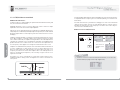
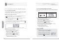
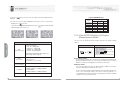
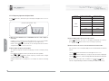
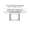
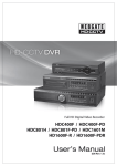
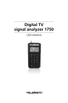
ontents
Chapter 1.
Getting
Started
1-1. Features ・・・・・・・・・・・・・・・・・・・・・・・・・・・・・・・・・・・・・・・・・・・・・・・・・・・・・・・・・・・・・・・・・・・・・・・・・・・・・・・・・・・・ 6
1-2. Safety instructions・・・・・・・・・・・・・・・・・・・・・・・・・・・・・・・・・・・・・・・・・・・・・・・・・・・・・・・・・・・・・・・・・・・・・・ 7
1-3. Unit overview ・・・・・・・・・・・・・・・・・・・・・・・・・・・・・・・・・・・・・・・・・・・・・・・・・・・・・・・・・・・・・・・・・・・・・・・・・・・・・ 9
1-4. Installation ・・・・・・・・・・・・・・・・・・・・・・・・・・・・・・・・・・・・・・・・・・・・・・・・・・・・・・・・・・・・・・・・・・・・・・・・・・・・・・・・・ 14
1-5. Charging battery ・・・・・・・・・・・・・・・・・・・・・・・・・・・・・・・・・・・・・・・・・・・・・・・・・・・・・・・・・・・・・・・・・・・・・・・・ 16
1-6. Cable specifications ・・・・・・・・・・・・・・・・・・・・・・・・・・・・・・・・・・・・・・・・・・・・・・・・・・・・・・・・・・・・・・・・・・・・ 17
Chapter 2.
Basic Operations
2-1. How to select measurement band・・・・・・・・・・・・・・・・・・・・・・・・・・・・・・・・・・・・・・・・・・・・・・・ 20
2-2. How to select measurement mode for analog channels・・・・・・・・・・・・・・・ 21
2-3. How to select measurement mode for digital channels・・・・・・・・・・・・・・・・ 22
2-4. How to enter channel number or frequency ・・・・・・・・・・・・・・・・・・・・・・・・・・・・・・・・ 23
2-5. How to select channel number or frequency ・・・・・・・・・・・・・・・・・・・・・・・・・・・・・・・ 24
2-6. How to change level measurement unit ・・・・・・・・・・・・・・・・・・・・・・・・・・・・・・・・・・・・・・ 25
2-7. How to select spectrum analyzer modes ・・・・・・・・・・・・・・・・・・・・・・・・・・・・・・・・・・・・・ 26
2-8. How to select scan modes・・・・・・・・・・・・・・・・・・・・・・・・・・・・・・・・・・・・・・・・・・・・・・・・・・・・・・・・・・・ 27
2-9. File(Saving/Reviewing/Printing/Deleting Measurement Files) ・・・・・ 28
2-10. How to select configuration modes ・・・・・・・・・・・・・・・・・・・・・・・・・・・・・・・・・・・・・・・・・・・ 30
Chapter 3.
Applications
3-1. Level measurement modes for analog channels
3-1-1. Video/Audio carrier levels measurement mode
・
・
・
・
・
・
・
・
・
・
・
・
・
・
・
・ 32
3-2-2. Carrier to Noise(C/N) measurement mode ・・・・・・・・・・・・・・・・・・・・・・・ 33
3-2-3. CTB/CSO measurement mode
・
・
・
・
・
・
・
・
・
・
・
・
・
・
・
・
・
・
・
・
・
・
・
・
・
・
・
・
・
・
・
・
・
・
・
・
・
・
・
・ 34
1
3-2. Level measurement modes for digital channels
3-8. Configuration modes
3-2-1. Channel Power measurement mode ・・・・・・・・・・・・・・・・・・・・・・・・ 36
3-8-1. Global Config mode ・・・・・・・・・・・・・・・・・・・・・・・・・・・・・・・・・・・・・・・・・・・・・・・・・・ 57
・
・
・
・
・
・
・
・
・
・
・
・
・
・
・
・ 37
3-8-2. Serial Port Config mode・・・・・・・・・・・・・・・・・・・・・・・・・・・・・・・・・・・・・・・・・・・・・ 58
3-2-3. SNR/MER, Pre-BER, Post-BER, Constellation Diagram ・・・・・・ 38
3-8-3. System Config mode ・・・・・・・・・・・・・・・・・・・・・・・・・・・・・・・・・・・・・・・・・・・・・・・・・ 59
3-2-2. Carrier to Noise(C/N) measurement mode
3-8-4. Channel/Frequency/Memory Config mode ・・・・・・・・・・・・・・・・・ 61
3-3. Line AC/DC & Battery voltages measurement mode
・
・
・
・
・
・
・
・
・
・ 41
3-8-5. Digital CH Config mode・・・・・・・・・・・・・・・・・・・・・・・・・・・・・・・・・・・・・・・・・・・・・・ 62
3-8-6. CSO Offset Config mode ・・・・・・・・・・・・・・・・・・・・・・・・・・・・・・・・・・・・・・・・・・・・ 64
3-8-7. C/N Config mode・・・・・・・・・・・・・・・・・・・・・・・・・・・・・・・・・・・・・・・・・・・・・・・・・・・・・・・ 65
3-4. Memory measurement band
3-4-1. Accessing to Memory CH Config ・・・・・・・・・・・・・・・・・・・・・・・・・・・・・・・ 42
3-8-8. Channel Plan ・・・・・・・・・・・・・・・・・・・・・・・・・・・・・・・・・・・・・・・・・・・・・・・・・・・・・・・・・・・・ 66
3-4-2. How to save channel and/or frequency ・・・・・・・・・・・・・・・・・・・・・・・ 42
3-8-9. Digital Limit Setup ・・・・・・・・・・・・・・・・・・・・・・・・・・・・・・・・・・・・・・・・・・・・・・・・・・・・ 66
3-9. How to connect to a computer ・・・・・・・・・・・・・・・・・・・・・・・・・・・・・・・・・・・・・・・・・・・・・ 67
3-5. Spectrum analyzer modes
3-5-1. Common operations ・・・・・・・・・・・・・・・・・・・・・・・・・・・・・・・・・・・・・・・・・・・・・・・・ 44
3-10. Cloning ・・・・・・・・・・・・・・・・・・・・・・・・・・・・・・・・・・・・・・・・・・・・・・・・・・・・・・・・・・・・・・・・・・・・・・・・・・・・・ 68
3-5-2. Channel spectrum analyzer mode・・・・・・・・・・・・・・・・・・・・・・・・・・・・・・ 45
3-5-3. Frequency spectrum analyzer mode ・・・・・・・・・・・・・・・・・・・・・・・・・・ 46
3-5-4. Tilt spectrum analyzer mode ・・・・・・・・・・・・・・・・・・・・・・・・・・・・・・・・・・・・・ 48
3-6. Scan modes ・・・・・・・・・・・・・・・・・・・・・・・・・・・・・・・・・・・・・・・・・・・・・・・・・・・・・・・・・・・・・・・・・・・・・・・ 50
Chapter 4.
Appendix
4-1. Specifications ・・・・・・・・・・・・・・・・・・・・・・・・・・・・・・・・・・・・・・・・・・・・・・・・・・・・・・・・・・・・・・・・・・・・・ 72
4-2. Warranty Information ・・・・・・・・・・・・・・・・・・・・・・・・・・・・・・・・・・・・・・・・・・・・・・・・・・・・・・・・・ 80
4-3. Warranty Card ・・・・・・・・・・・・・・・・・・・・・・・・・・・・・・・・・・・・・・・・・・・・・・・・・・・・・・・・・・・・・・・・・・・・ 81
3-7. File
3-7-1. How to save measurements ・・・・・・・・・・・・・・・・・・・・・・・・・・・・・・・・・・・・・ 52
3-7-2. How to review the saved measurements ・・・・・・・・・・・・・・・・・・・・ 53
3-7-3. How to delete measurement file(s) ・・・・・・・・・・・・・・・・・・・・・・・・・・・・・ 54
3-7-4. How to print the saved measurements ・・・・・・・・・・・・・・・・・・・・・・・・・55
3-7-5. How to print a current display ・・・・・・・・・・・・・・・・・・・・・・・・・・・・・・・・・・・ 56
2
3
1-1. Features
1-2. Safety instructions
1-3. Unit overview
1-4. Installation
1-5. Charging battery
1-6. Cable specifications
2) Digital channels :
Telemann Digital TV Signal Analyzers are the full-featured signal analyzers with
complete spectrum analyzers(channel/frequency/tilt spectrum analyzers), which
perform the level measurement, C/N measurement, CTB/CSO measurement for
analog channels and power measurement as well as C/N measurement for digital
channels. Scan, measurement files(saving/reviewing/deleting/printing) and
connecting to a computer or printer and etc. are also performed with accuracy and
easiness.
[ 1720/1730 VSB/QAM, 1720/1730 QAM, 1720/1730 OFDM ]
- SNR/MER(Modulation Error Rate)
- EVM(Error Vector Magnitude)
- Constellation Diagram
Accordingly, these models are the optimal units for the installation and maintenance
of analog/digital television signal reception and distribution systems, which include
any optional frequency, MATV (Master Antenna Television), CATV (Cable Television)
and MMDS (Multi-channel Multi-point Distribution Systems), working a frequency
range of 5MHz to 870MHz(or 1GHz→1730 VSB/QAM, 1730 QAM, 1730 OFDM)
The weight is less than 1kg including two rechargeable battery packs. 128 X 64 dot
matrix LCD screen shows measurement data clearly through both graphical and
numerical form.
○1720/1730 VSB/QAM are the optimal signal analyzers to test and measure both
digital TV signals(8/16VSB) and digital CATV signals(16/32/64/128/256QAM).
Especially, these models give users the capacity to measure SNR(MER), EVM,
Pre-BER, Post-BER, Constellation Diagram very easily and correctly, which are
very important measurement factors for the digital signal quality.
Chapter 1. Getting Started
Chapter 1. Getting Started
1-1. Features
- Power measurement(QAM, VSB, COFDM, QPSK signals)
- Carrier to Noise(C/N) ratio measurement
All models are very comfortable and safe as they can be carried in a bag with a
shoulder strap and can be used only opening the bag.
The contents of this manual will describe the care and operation of Telemann digital
TV signal analyzers.
1-2. Safety Instructions
○1720/1730 QAM & 1720/1730 QAM(A) are the very excellent signal analyzers of
choice for field testing of QAM digital signals on your cable TV system. They
demodulate and accurately measure the QAM signals carried through the cable
system. They provide the measurement power the field technicians need for the
latest 16/32/64/128/256QAM digital technologies and are very simple to use,
measuring SNR(MER), EVM, Pre-BER, Post-BER, Constellation Diagram.
However, 1720/1730 QAM(A) measure digital level, Pre-BER, SNR (MER) only for
digital signal.
The following contents are for the prevention of user’
s damage and property loss.
Read them thoroughly and use the unit rightly.
○1720 /1730 OFDM are the best choice for the field technicians to measure digital
terrestrial TV(DVB-T standard). They demodulate and accurately measure the
COFDM signals carried through the terrestrial TV system. They are very simple
and convenient to use and measure SNR(MER), EVM, Pre-BER, Post-BER,
Constellation Diagram for the digital TV channels.
○ Don’
t disassemble, repair and remodel the unit as you pleases.
When repair is needed, make contact with a service center.
Telemann Digital TV Signal Analyzers enable users to measure the followings. :
○ Observe the ranges of power supply and measurements specified in the users
manual.
This symbol is intended to alert users of possible dangers in operating this unit.
General
○ After being fully aware of users manual, operate and install the unit.
1) Analog channels :
- Video/Audio carrier levels measurement
- Carrier to Noise(C/N) ratio measurement
- CTB/CSO measurement
6
○ The unit and accessories should be installed, operated and maintained only
authorized personnel. Faulty installation or service may result in an accident and
make invalid warranty.
7
○ Use the unit in the temperature range from 0 to 60℃
Maintenance
Chapter 1. Getting Started
Chapter 1. Getting Started
Circumstances
○ Unplug the unit from the wall outlet before cleaning. Don’
t use liquid, wax and
aerosol cleaner. Use a dry cloth.
○ Keep the maximum humidity of unit under 80%.
○ Use a dry cloth in cleaning contacting parts. Don’
t use a wet cloth.
Installation
○ Don’
t connect any cables which are not offered by manufacturer.
It may cause fatal damage to the unit.
○ Only use the chargeable batteries, adapter, RS232C cable, and cloning cable
provided by Telemann. Using unauthorized accessories could avoid warranty.
1-3. Unit Overviews
The descriptions for each part and its function of Digital TV Signal Analyzer enable
users to understand and operate the unit well.
■Front View
○ Keep in mind that the input level of F-JJ connector is 100 VAC rms/50-60MHz.
F-JJ connector
Battery Charge
“F”
-male base connector
○ Don’
t supply the power to the unit without setting two packs of rechargeable
batteries. It may give a serious damage to inner circuit.
128 X 64 dot
matrix LCD
(with backlight)
○ Recharge the batteries after being discharged completely, not to shorten their life
span.
○ Before using adapter, check whether its power is united to the main power. Or the
inner circuit may be damaged.
Keypad
○ Use a car cigarette adapter with 13.8V. In case of a large sized car or freight car,
however, use the adapter with 24V. Or the inner circuit may be damaged.
○ Use a car cigarette adapter with 0.75A fuse. The inner circuit may be damaged.
○ When you use a car cigarette adapter, get the car started before charging the
batteries. Otherwise, the batteries may not be fully recharged or the car may be
discharged.
8
Status Indicator
(Battery Charge)
Status Indicator
(Remote Moade)
9
Chapter 1. Getting Started
Chapter 1. Getting Started
■Keypad - Each button’
s name and function
■Back View
The unit has a 21-button keypad. By pressing designated button combinations, you
can access to all the button functions of a keypad.
1) Six measurement buttons
2) Twelve Alpha-Numeric-Arrow buttons
3) One power button
4) One enter button
5) One LCD backlight/Reset button
Logo : TELEMANN
Model Number(MODEL) :
Serial Number(S/N) :
Manufacturer : Telemann Corporation
Website : http://www.telemannco.com
Origin : MADE IN KOREA
Spectrum Analyzer Mode Button [2]
Level Measurement
Button [1]
Level Measurement
Mode Button [3]
Scan Mode Button [4]
Sub-Functions
Support Button [6]
Config Mode
Button [5]
■Bottom View
Alpha-Numeric-Arrow
Buttons [10]
Power Button [7]
Adapter port
Enter Button [9]
RS232C interface or
Cloning cable port
LCD backlight/Reset Btton [8]
10
11
(1) When you want to measure video/audio carrier levels for each
channel or frequency,
(2) When you want to select the measurement band among MATV,
CATV, FREQ and MEMORY
7] POWER BUTTON
Chapter 1. Getting Started
Chapter 1. Getting Started
1] LEVEL MEASUREMENT BUTTON
When you want to turn power on or off,
8] LCD BACKLIGHT/RESET BUTTON
1) When you want to turn LCD backlight on or off,
2] SPECTRUM ANALYZER MODE BUTTON
When you wan to select channel spectrum analyzer, frequency
spectrum analyzer or tilt spectrum analyzer,
3] LEVEL MEASUREMENT MODE BUTTON
(1) When you want to select the level measurement modes such as
C/N, CTB/CSO, SNR/MER, BER, Constellation Diagram and etc.
for the purpose of measuring signal levels,
(2) In the spectrum analyzer modes, when you want to display“ㅗ”
cursor on the LCD screen,
2) When you want to initialize some parameters as below,
9] ENTER BUTTON
It is used for various functions and depended on the measurement
operations. Refer to Chap. 3 Applications.
10] ALPHA-NUMERIC-ARROW BUTTONS
These buttons perform their own functions as well as other
functions. Refer to Chap. 3 Applications.
(3) In the TILT CHANNEL LIST and MEMORY CH CONFIG, when you
want to select MATV/CATV/FREQ/BLANK(or Deletion),
(4) When you enter name in the GLOBAL CONFIG or when you
change a big English letter to a small English letter, and vice
versa in the file directory,
4] SCAN MODE BUTTON
(1) When you want to scan all active signal levels,
(2) When you want to save all active signal levels in a file,
5] CONFIG MODE BUTTON
When you want to change and set parameters in connection with all
measurement modes,
IN MIND!!!
IMPORTANT : KEEP
If you press
button for more than 2 seconds, the following
parameters will be initialized as same as factory default settings.
(1) Level unit ▷ dBμ
V
(2) The item of Audio Measure in the CH/FREQ/MEM CONFIG ▷ Direct
(3) Level indication in the scan mode ▷ LEVEL ONLY
(4) Reference level in the scan mode ▷ 60dBμ
V
(5) Frequency of FREQ measurement band ▷ 250MHz
(6) Span of frequency spectrum analyzer ▷ 11MHz
(7) Initial display ▷ MATV measurement band
(8) LCD contrast level ▷ 3
(9) English letter ▷ Big English letter
6] SUB-FUNCTIONS SUPPORT BUTTON
When you want to activate various sub-functions,
12
13
6. Connect a coaxial cable to the F-JJ connector.
1. Check out a packing status.
7. Press the power button(
○ Every unit should be passed quality test at manufacturer’
s factory before
delivery.
Chapter 1. Getting Started
Chapter 1. Getting Started
1-4. Installation
).
Then, the following display will appear on the LCD screen for a while and it will be
changed to the display of MATV measurement band soon. It is called the initial
display.
2. Unpack a packing box.
○ If a packing box was damaged during transportation, contact to the dealer or
service center promptly. In this case, keep the damaged packing box as it was,
so that we can grasp the point of problem correctly. We will try to solve it fast
and correctly.
3. Check out if the following things are included in a packing
box correctly.
When this display appears on the screen, press the power button continuously to
stop the screen.
If data transfer to a computer or printer is necessary, connect RS232 cable to a
computer or printer as below;
User
Manual
[ Portable bag
[ shoulder strap ] [ F-JJ connector ]
including the unit ]
[ adapter ]
[ Users manual ]
If cloning function is necessary, connect two units using a cloning cable as
below;
○ If anything is missed, contact to the dealer or Telemann.
4. Connect the adapter to the unit in order to charge/recharge the
batteries.
○ 2packs(8ea.) of Ni-MH rechargeable batteries(total 9.6V) are putted into the
back of the unit.
5. After charging, connect F-JJ connector to the unit.
14
15
1-6. Cable Specifcations
1. All Telemann’
s units can interrupt improper power supply in order to protect their
inner circuits from any possible damage.
There are three cables associated with the operation of Telemann’
s digital TV signal
analyzers as below;
○ Please turn the damaged unit to our A/S as the fuse should be replaced. In this
case, repairing cost is charged to buyer regardless of the warranty period.
2. It is recommended to charge battery with power being turn off. In case of emergency,
however, with its function protecting any damage from overcharge, charging
battery during operation is possible.
○ In this case, we, Telemann, are not responsible for any damage that may happen.
3. After discharging completely, it takes for more than 8-hours to fully recharge
batteries. In case of emergency, however, you can operate the unit after a 2-hour
recharge as it has the fast charging function that makes the batteries recharged up
to 60% within two hours.
Chapter 1. Getting Started
Chapter 1. Getting Started
1-5. Charging Battery
1) Coaxial Cable : option
: It is connected between F-JJ connector of the unit and the adapter of line to be
measured.
2) RS232C interface cable : option
: Data transfer cable to a computer or printer
3) Cloning Cable : option
: It is used for cloning.
○The charging time of batteries depends on the battery status.
4. The unit has a the battery voltage measurement function.
[See page 41 in Chap 3. Applications]
5. The battery charge level is shown on the bottom left of the LCD screen.
When the battery charge level becomes low(
), you should recharge the
batteries. If the battery charge level becomes exceedingly low, the unit will
automatically power off.
16
[coaxial cable]
[RS232C cable]
[cloning cable]
If any problem happens, contact to the dealer or Telemann and in case of
emergency, call at 82-32-678-8566/8567(overseas), 032-678-8566/8567
(domestic) or email to [email protected]. We will try to solve the problem
fast and correctly.
17
2-1. How to select measurement band
2-2. How to select measurement mode for analog channels
2-3. How to select measurement mode for digital channels
2-4. How to enter channel number or frequency
2-5. How to select channel number or frequency
2-6. How to change level measurement unit
2-7. How to select spectrum analyzer modes
2-8. How to select scan modes
2-9. File(Saving/Reviewing/Printing/Deleting Measurement Files)
2-10. How to select configuration modes
Theses example measurements are designed to acquaint the first user
with Telemann Digital TV signal Analyzers. They provide a foundation for
understanding how to use Telemann Digital TV signal Analyzers. For a
more complete overview of the unit and its capabilities, refer to Chap. 3
Application of this user manual.
Measurement bands divided into the followings. :
2-2. How to Select Measurement Modes
for Analog Channels
(1) MATV measurement band
: If you want to measure MATV channels, measure them in this band.
1. Press
(2) CATV measurement band
: If you want to measure CATV channels, measure them in this band.
2. Press
button to select measurement mode. Then, the selected measurement
modes will appear on the screen, however, they will appear differently whether a
channel or frequency set as digital or analog.
Chapter 2. Basic Operations
(3) FREQ(Frequency) measurement band
: If you want to measure any frequency like FM signal, measure it in this band.
(4) MEMORY measurement band
: If you want to measure any channel and/or frequency, you can store maximum
30 channels and/or frequencies in MEMORY CH CONFIG, which can be
measured in this band.
The icon,
button to select measurement band.
Chapter 2. Basic Operations
2-1. How to Select Measurement Band
on the screen means that the channel or frequency set as analog.
Press
button repeatedly, and measurement bands will appear on the
screen as below;
[Video/Audio carrier levels measurement mode]
[MATV measurement band]
[C/N measurement mode]
[CATV measurement band]
[Line AC/DC & Battery
voltages measurement mode]
[MEMORY measurement band]
[CTB/CSO measurement mode]
[FREQUENCY measurement band]
20
21
2-4. How to Enter Channel Number or
Frequency
The icon,
Press
button to select the measurement band and enter the channel number
or frequency that you want to measure. The message, Set CH No. or Set Freq will
appear together with the entered channel number or frequency on the bottom of
screen. To terminate the entry, press
button.
on the screen means that the channel or frequency set as digital.
Chapter 2. Basic Operations
★ Example : If you want to enter 175.25MHz in FREQ measurement band, press
buttons as follows;
[Power measurement mode]
[C/N measurement mode]
Chapter 2. Basic Operations
2-3. How to Select Measurement Modes
for Digital Channels
[Line AC/DC & Battery
measurement mode]
[How to enter the alphabet channels]
[SNR/MER, BER measurement mode]
NOTE!!!
1) CCIR channel plan
○ 1101 ~ 1109 / 110 ~141 → S01 ~ S09 / S10 ~ S41
○ 201~204 → T1 ~ T4
○ 301 ~ 302 → Z1 ~ Z2
○ 401/ 402 / 403 → X / Y / Z
2) EIA channel plan
○ 201 ~ 204/ 211 ~ 215 → D1 ~ D4/ D11 ~ D15
Example : Channel S01 in CCIR
channel
S01
NOTE!!!
1. SNR/MER, BER measurement mode will appear on the screen, but they will
not work actually in model 1702 and 1703.
2. In order to set the channel or frequency as analog or digital, see pages,
42/62/66 in Chap. 3 Applications.
22
You can also enter memory number in MEMOEY measurement band using the
same method mentioned above. In this case, however, you must enter channel
and/or frequency that you want to measure in the MEMORY CH CONFIG first.
(See page 42 in Chap 3 Applications.]
23
2-5. How to Select Channel Number or
Frequency
2-6. How to Change Level Measurement Unit
You can change level measurement unit as below;
In order to select the channel number or frequency, press buttons as follows.
1. In Video/Audio carrier levels measurement mode,
When
Chapter 2. Basic Operations
Press
Press
(Number will decrease)
and
buttons in order.
button is pressed repeatedly, the level measurement unit will be changed to
dBμ
V → dBmV → dBm in turn.
The level measurement unit set as dBμ
V at the factory.
2. In GLOBAL CONFIG mode
: See page 57~58 in Chap. 3 Applications.
(Number will increase)
Chapter 2. Basic Operations
: Press
NOTE!!!
1. If you press
button or
button once, channel number or frequency
will decrease or increase one by one.
And also, if you hold down these buttons continuously, channel number or
frequency will decrease or increase very fast.
2. In MEMORY measurement band, you can select the desired memory number
using the same method mentioned above.
In this case, however, you must enter channel and/or frequency that you want
to measure in the MEMORY CH CONFIG first.
(See page 42 in Chap.3 Applications)
24
25
2-7. How to Select Spectrum Analyzer Modes
2-8. How to Select Scan Modes
There are three spectrum analyzer modes as follows.
There are four scan modes as follows. : MTV SCAN mode, CTV SCAN mode, MEM
SCAN mode, TILT SCAN mode
(1) Channel spectrum analyzer mode
: It shows status of both video and audio carrier levels of all active channels in one
screen.
In order to select scan modes, press
button.
The selected scan mode will appear as below;
(3) Tilt spectrum analyzer mode
: To activate this mode, the user must save channel or frequency into the TILT
CHANNEL LIST first, in where max. 15 channels or frequencies can be entered.
It arranges the lowest frequency on the left and the highest one at the right in
the screen, regardless the orders of entering channels and/or frequencies into
the TILT CHANNEL LIST and also, display the difference between those of video
levels at the bottom of screen that is called“TILT SLOPE”as well.
In order to select spectrum analyzer modes, press
button repeatedly.
Channel spectrum analyzer mode, frequency spectrum mode and tilt spectrum
analyzer mode will appear on the screen.
[Channel Spectrum Analyzer] [Frequency Spectrum Analyzer]
[MATV measurement band]
[MTV scan mode]
[CATV measurement band]
[CTV scan mode]
[MEMORY measurement band]
[MEM scan mode]
[TILT spectrum analyzer mode]
[TILT scan mode]
Chapter 2. Basic Operations
Chapter 2. Basic Operations
(2) Frequency spectrum analyzer mode
: On the basis of the entered channel’
s frequency by the user, this mode shows
its video carrier level and enlarge/reduce the range of its span.
[Tilt Spectrum Analyzer]
NOTE!!!
1. In order to show tilt spectrum analyzer mode on the screen, you must enter
channel or frequency in the TILT CHANNEL LIST first. (See page 48 in Chap. 3
Applications)
2. When FREQ measurement band is selected, channel spectrum analyzer
mode can’
t be seen on the screen.
26
27
If you want to delete all files at once, press
button for more than
2 seconds. The warning message will appear on the screen. If you want to delete all
files surely, press
button.
2-9. File
2-9-1. How to save measurements
Chapter 2. Basic Operations
or
2-9-2. How to review/delete/print measurement files
In order to review measurement files, you have to accede the file directory first by
pressing
button in spectrum analyzer modes or scan modes
and also, press
and
buttons in order in level measurement modes.
You can print all files at once or one file. Open the file directory first. If you want to
print all files at once, press
button.
"Print All?" message is appeared on the screen and press
button.
If you want to print one file, press
or
button to select the file and then,
press
button to open the selected file.
Press
button, and "Print Now" message is appeared.
Press
button for printing.
Chapter 2. Basic Operations
In spectrum analyzer modes or scan modes, you can save measurements by pressing
button. You can make a file and it will be added into the file directory.
Then, you select the wanted file pressing
or
button and press
button.
The saved measurement data including the selected file will appear on the screen.
or
In order to delete measurement file(s), you have to open the file directory first as
mentioned above.
Then, if you want to delete one file, you select it pressing
press
and
buttons in sequence.
28
or
button and
Before printing, please check the followings!!
1. Connect your computer with printer.
2. Connect the unit to your computer using RS232C cable.
3. Install the Telemann software, TC-05 at your computer.
4. Adjust the communication parameters of your computer or printer to those of
TC-05.
29
2-10. How to Select Configuration Modes
Press
Press
button repeatedly, and configuration modes will appear on LCD screen in turn.
button and next,
button to return to a previous screen.
Chapter 2. Basic Operations
[GLOBAL CONFIG]
[SERIAL PORT CONFIG]
[CSO OFFSET CONFIG]
3-1. Level measurement modes for analog channels
3-1-1. Video/Audio carrier levels measurement
mode
3-2-2. Carrier to Noise(C/N) measurement mode
3-2-3. CTB/CSO measurement mode
3-2. Level measurement modes for digital channels
3-2-1. Channel Power measurement mode
3-2-2. Carrier to Noise(C/N) measurement mode
3-2-3. SNR/MER, Pre-BER, Post-BER,
Constellation Diagram
3-3. Line AC/DC & Battery voltages measurement mode
[SYSTEM CONFIG]
[C/N CONFIG]
[DIGITAL LIMET SETUP CONFIG]
[TILT CHANNEL LIST]
3-4. Memory measurement band
3-4-1. Accessing to Memory CH Config
3-4-2. How to save channel and/or frequency
3-5. Spectrum analyzer modes
3-5-1. Common operations
3-5-2. Channel spectrum analyzer mode
3-5-3. Frequency spectrum analyzer mode
3-5-4. Tilt spectrum analyzer mode
3-7. File
3-7-1. How to save measurements
3-7-2. How to review the saved measurements
3-7-3. How to delete measurement file(s)
3-7-4. How to print the saved measurement
3-7-5. How to print a current display
3-8. Configuration modes
3-8-1. Global Config mode
3-8-2. Serial Port Config mode
3-8-3. System Config mode
3-8-4. Channel/Frequency/Memory Config
mode
3-8-5. Digital CH Config mode
3-8-6. CSO Offset Config mode
3-8-7. C/N Config mode
3-8-8. Channel Plan
3-8-9. Digital Limit Setup
3-9. How to connect to a computer
3-10. Cloning
3-6. Scan modes
This chapter provides detailed operations of Digital TV signal Analyzers. It
includes the detailed examples the various displays of the selected modes of
operation.
[CH PLAN]
[DIGITAL CH CONFIG]
[CH/FREQ/MEM CONFIG]
30
3-1. Level Measurement for Analog Channels
3-1-2. Carrier to Noise(C/N) Measurement Mode
3-1-1. Video/Audio Carrier Levels Measurement Mode
C/N ratio can be measured when video level is over 50dB and you can set
parameters in connection with C/N ratio measurement mode in C/N CONFIG mode.
You can measure both video and audio carrier levels for the selected channel in this
video/audio level measurement mode and see the ratio between video and audio
levels as well.
Press buttons
Display
Press buttons
Displays
[C/N Ratio Measurement Mode]
Chapter 3. Applications
Ratio between Video and
Audio Carrier Levels
◆ Information shown on the displays...
ⓐ measurement band(shown as CATV on the displays)
ⓑ channel number(shown as 07 on the displays)
ⓒ analog type(shown as
on the displays)
ⓓ video/audio carrier levels measurement mode(shown as on the displays)
ⓔ battery status (shown as
on the displays)
ⓕ frequency(shown as 189.25MHz on the displays)
ⓖ video carrier level(shown as 57.7dBμ
V on the displays)
ⓗ audio carrier level(shown as 50.1dB on the upper display)
ⓘ V/A ratio(shown as △-7.6dB on the lower display)
ⓙ bar graph(The left bar graph shows video carrier level and the right one shows
audio carrier level.) : 10dBμ
V/10dBmV/10dBm unit per division
◆ Information shown on the display..
ⓐ measurement band(shown as CATV on the display)
ⓑ channel number(shown as 07 on the display)
ⓒ analog type(shown as
on the display)
ⓓ C/N ratio measurement mode(shown as
on the display)
ⓔ battery status(shown as
on the display)
ⓕ frequency(189.25MHz on the top display)
ⓖ frequency offset(shown as OFS 4.8MHz on the display)
ⓗ noise measurement bandwidth(shown as B/W 8.0MHz on the display)
ⓘ bar graph(The left bar graph shows video carrier level and the right one shows
audio carrier level.) : 10dBμ
V/10dBmV/10dBm unit per division
Chapter 3. Applications
Video/Audio Carrier Levels
Measurement Mode
NOTE!!!
In order to set parameters in connection with C/N
ratio measurement mode such as frequency
offset, noise measurement bandwidth, noise
frequency, access to the C/N CONFIG.
(See page 65. )
NOTE!!!
1. In order to see V/A ratio, press
button. It will appear at the place of ⓗ
like△ -7.6 dB as shown in the lower display.
2. V/A ratio can be set in CH/FREQ/MEM CONFIG as well.
(See page 61~62 in Chap. 3 Applications)
32
33
■ What CTB and CSO are..
In order to help user’
s understanding, we explain what CTB and CSO are briefly and
then, their measurement methods.
Amplitude distortion occurs in a system, subsystem, or device when the output
amplitude is not a linear function of the input amplitude.
Main factors for the signal distortion that is made by such amplitude distortion are
CSO(Composite Second Order) and CTB(Composite Triple Beat). Such CSO and CTB
distortions appear within a certain frequency and cause the beat interference on the
TV display.
Telemann Digital Signal Analyzers define and display the worst measurement value
accompanied with the frequency offset as CSO value.(Namely, the CSO value has
minor value.)
The CTB measurement is performed accordingly to the CSO. If all transmitted
channels have the video carrier at the same position within the channel, then the
CTB beat will show up at the same frequency as the video carrier. That’
s why the
carrier of channel should be turn off.
■ How to measure CTB/CSO values
Press buttons
Chapter 3. Applications
Composite Triple Beat(CTB) is a commonly encountered manifestation of coherent
noise. When it appears, it normally signifies that somewhere between the signal
source and the subscriber, an amplifier is being overdriven. The CTB impairment is
caused by the cumulative effect of hundreds of third order intermodulation beat
products. Graininess or a similar texture effect characterizes this impairment over
the entire picture, which appears as a tearing in the horizontal lines of the screen.
[CTB/CSO Measurement Mode]
Turn carrier off
and press enter
button.
Composite Second Order beats (CSO) are also resulted from nonlinear behavior in
electronic components. In cable systems the source is most frequently the laser
drivers for optical fiber links, and sometimes the optical fiber itself. CSO is less
frequently encountered in coaxial cable amplifiers due to the widespread use of
what are called push-pull amplifiers, which usually relegates CSO to lesser
significance than CTB.
A CSO beat is a cluster of hundreds of second order single frequency intermodulation products. Grainy texture or diagonal lines can be occurred over the
entire picture.
Displays
Chapter 3. Applications
3-1-3. CTB/CSO Measurement Mode
NOTE!!!
In order to set offsets in connection with CSO measurement, access to the CSO
OFFSET CONFIG.(See page 64~65 in Chap. 3 Applications)
35
34
35
3-2. Level measurement for digital channels
3-2-2. Carrier to Noise(C/N) Measurement Mode
3-2-1. Power Measurement Mode
In level measurement mode for digital channel, C/N ratio shows the ratio between
digital channel average power and noise power. It can be measured when video level
is over 40dB.
Telemann Digital TV Signal Analyzers measure the average power within the digital
channel bandwidth. In addition, when channel set as digital, its own frequency is
changed to the center frequency, which will display on the screen.
Press buttons
Display
■ How to measure digital channel power
1. To change digital bandwidth, access to the CH/FREQ/MEM CONFIG by pressing
button repeatedly.(See page 61~62 in Chap. 3 Applications)
Chapter 3. Applications
For example, when Channel 25 is defined as digital in the CH PLAN or CH CONFIG
and the modulation type is set as QAM64 in the DIGITAL CH CONFIG, press
button repeatedly. The following will appear on the screen.
◆ Information shown on the display..
ⓐ measurement band(shown as CATV on the display)
ⓑ channel number(shown as 25 on the display)
ⓒ digital type(shown as
on the display)
ⓓ modulation type(shown as QAM64 on the display)
ⓔ C/N ratio measurement mode(shown as C/N on the display)
ⓕ battery status(shown as
on the display)
ⓖ frequency(shown as 506.00MHz on the display)
ⓗ frequency offset(shown as OFS 4.8MHz on the display)
ⓘ noise measurement bandwidth(shown as B/W 8.0MHz on the display)
ⓙ ratio between digital channel power and noise power
(shown as 24.3dB on the display)
ⓚ bar graph(It shows video carrier level)
: 10dBμ
V/10dBmV/10dBm unit per division
Chapter 3. Applications
2. To change modulation type(ⓓ), annex type, symbol rate and spectrum inversion,
access to the DIGITAL CH CONFIG by pressing
button repeatedly.
(62~64. in Chap. 3 Applications)
[C/N ratio measurement mode]
[Example : Digital Channel Average Power Measurement - QAM64]
NOTE!!!
◆ Information shown on the display..
ⓐ measurement band(shown as CATV on the display)
ⓑ channel number(shown as 25 on the display)
ⓒ digital type(shown as
on the display)
ⓓ modulation type(shown as QAM64 on the display)
ⓔ digital bandwidth(shown as 8.0MHz one the display)
ⓕ battery status(shown as
on the display)
ⓖ frequency(shown as 506.00MHz on the display)
ⓗ video carrier level(shown as 58.4dBμ
V on the display)
ⓘ bar graph(It shows video carrier level.)
: 10dBμ
V/10dBmV/10dBm unit per division
36
1. In order to see video carrier level, press
button.
It will replace in the figures of ⓗ and ⓘ on the screen.
2. In order to set parameters in connection with
C/N CONFIG such as frequency offset and noise
measurement bandwidth, access to the C/N
CONFIG by pressing
button. (See page 60.)
37
3-2-3. SNR/MER, Pre-BER, Post-BER, Constellation Diagram
You have to set modulation type, annex type, symbol rate, spectrum inversion as
same as your measurement conditions and the channel or frequency as digital type
before measuring SNR/MER, Pre-BER, Post-BER, Constellation diagram.
Then, press
button till Pre-BER, SNR/MER measurement mode appear on the
LCD screen. The following displays are examples of Pre-BER, SNR/MER
measurement mode when modulations are selected as VSB, QAM64, COFDM,
respectively.
1
3
5
7
9
[VSB Constellation Diagram]
1
3
5
7
9
1
3
Chapter 3. Applications
[Pre-BER, SNR/MER Measurement Mode : VSB mode]
Chapter 3. Applications
[QAM Constellation Diagram]
5
7
9
[COFDM Constellation Diagram]
[Pre-BER, SNR/MER Measurement Mode : QAM64 mode]
1) In order to zoom the upper left area(①), press
2) In order to zoom the upper right area(③), press
3) In order to zoom the lower left area(⑦), press
[Pre-BER, SNR/MER Measurement Mode : COFDM mode]
4) In order to zoom the lower right area(⑨) , press
5) In order to zoom the center area[⑤], press
If you want to display constellation diagram, press
appeared on the LCD screen like the following;
38
button.
button.
button.
button.
button.
button, and this will be
39
[ Typical SNR/MER Results ]
button one more time the original constellation diagram will be
Grade
6) In order to restart Pre-BER, SNR/MER measurement as well as Constellation
diagram, press
two times.
If you want to see VSB/QAM/COFDM parameters, press
display will appear on the LCD screen.
[VSB Parameters]
[QAM Parameters]
button, and the following
[COFDM Parameters]
Digital Signal Measurement
Chapter 3. Applications
MER
(Modulation Error Rate)
Very Excellent
Excellent
Good
Acceptable
Marginal
Dangerous
* Measurement Range
- VSB : 15 ~ 37dB(±2dB)
- 64QAM : 22 ~ 37dB(±2dB)
- 256QAM : 28 ~ 37dB(±2dB)
- COFDM : up to 37dB(±2dB)
BER
EVM
(Error Vector Magnitude)
Lock Range
Data Logger
40
* 1720/1730QAM & 1720/1730QAM(A)
→10E -2 to 10 E-9
* Other Models : 10E -2 to 10 E-8
* Measurement Range : 1.5% ~ 8.0%
* 1720/1730 VSB/QAM, 1720/1730 OFDM
: 45dBμ
V(-15dBmV) ~ 120dBμ
V(+60dBmV)
* 1720/1730 QAM
: 50dBμ
V(-10dBmV) ~ 120dBμ
V(+60dBmV)
Level-MER, Level-BER
36
35
31
28
24
22
37
36
34
31
29
28
VSB
34
32
28
22
19
18
3-3. Line AC/DC & Battery Voltages
Measurement Mode
You can check line AC/DC & Battery voltages regardless of analog or digital
channel.
Press buttons
Display
line voltage
battery voltage
* Max. displayed SNR/MER is about 34dB on the
portable type analyzer.(Typical)
(Bit Error Rate)
SNR/MER
QAM64 QAM256
Chapter 3. Applications
If you press
displayed.
[Line AC/DC & Battery Voltages Measurement Mode]
■ Line AC/DC voltage
Measuring range is AC/DC 10V~110V. The unit is designed to identify input voltage
polarity and AC/DC automatically. If AC voltage is merged into DC voltage in
duplicate, the larger level is displayed. Please be aware of this feature.
■ Battery voltage
This is an extra option to measure the battery voltage in addition to the battery
level meter displayed at the bottom of LCD screen.
The level for battery voltage is displayed together with line AC/DC voltage in the
same screen. Measuring range is 8V~15V. To avoid any problem, it is
recommended to use 2packs of Ni-MH rechargeable batteries(4.8V, 2,100mAH)
composed of 4 cells attached to the unit.
41
3-4. Memory Measurement Band
■ To enter channel or frequency..
1. Press
3-4-1. Accessing to MEMORY CHAN CONFIG
Telemann unit has a unique measurement band, allowing users to save and
measure maximum 30 channels and/or frequencies. To use this function, you have
to save your desired channel or frequency in MEMORY CHAN CONFIG first and then,
measure it in MEMORY measurement band.
button.
: You can enter MTV → CTV → FREQUENCY → BLANK(DELETION) will appear
at the place of ⓒ in sequence.
2. Press your desired numeric button to enter numeric numbers.
: When you enter frequency and need a decimal point, press
button.
Displays
Press buttons
3. Press
and
or
or
or
button.
: One column or rank will move to left/right/up/down, respectively.
4. Press
[Memory Measurement Band]
and
or
button.
: Six columns or ranks will move to up/down, respectively.
Chapter 3. Applications
Chapter 3. Applications
NOTE!!!
After entering your desired channel and/or frequency in MEMORY CH
Press it for more than 2 seconds.
CONFIG, press
[MEMORY CHAN CONFIG]
button to measure the entered channel or frequency
in MEMORY measurement band.
3-4-2. How to Enter Channel and/or Frequency
◆ Information shown on the display..
ⓐ MEMORY CHAN CONFIG
ⓑ memory number(NO on the display)
ⓒ measurement band together with channel
or frequency (CHAN on the display)
ⓓ analog or digital type(TYPE on the display)
ⓔ scan activate/inactivate
(SCAN on the display)
ⓕ remote mode activate/inactivate
(AUTO on the display)
42
[MEMORY CHAN CONFIG]
43
3-5. Spectrum Analyzer Modes
3-5-1. Common Operations
As mentioned on page 26 in Chap. 2 Basic Operations, there are three spectrum
analyzer modes : Channel Spectrum Analyzer Mode, Frequency Spectrum Analyzer
Mode and Tilt Spectrum Analyzer Mode. The followings are common operations
applying to all spectrum analyzer modes.
3-5-2. Channel Spectrum Analyzer Mode
When MATV or CATV or MEMORY measurement band is selected, press
button one time, Channel Spectrum Analyzer will appear on the
screen like the following display. Please note that when FREQUENCY measurement
band is selected, it will not appear.
1. What is the level measurement unit?
Chapter 3. Applications
2. How to adjust the reference level? What is the automatic reference level
setting function?
[Channel Spectrum Analyzer Mode]
The highest one among the measured channel levels will be set as the reference
level automatically and it will be shown at the top left on the screen. This is called
“Automatic Reference Level Setting Function”
.
・ Press
or
to adjust the reference level manually.
(1) How to adjust Sweep Span?
The smallest channel is shown at the left bottom of screen and the largest one is
shown at the right bottom of screen as above. The range between the smallest
and largest channel is called“Sweep Span”
.
Press
or
button. Sweep span will be decreased or expanded.
At this time, the reference channel will be changed according to the selected
sweep span.
3. How to adjust the level unit per division?
(1) 15~120dBμ
V with the unit of 5dBμ
V or 10dBμ
V per division.
(2) Press
button to adjust the level unit per division.
4. How to see the reference line and move it?
Press
button, and the reference line will appear on the screen.
Then, press
or
button to move it to up or down.
5. How to see the vertical line and move it?
Press
button, and the vertical line will appear on the screen.
Then, press
or
button to move it to the left or light, respectively.
44
Chapter 3. Applications
dBμ
V
(2) How to adjust channel
When
or
button is pressed, channel will be decreased or increased.
And when these buttons are keep pressing, channel will be decreased or
increased very fast.
(3) How to display video/audio carrier levels on the screen
Press
button first. The cursor,“ㅗ”will appear at the bottom of screen.
Then, press
or
button. The cursor will move to the left or right and also,
video carrier level, audio carrier level and channel number will appear. V and A mean
video carrier level and audio carrier level, respectively. For example, 37, 37V and 37A
means channel 37, video carrier level for channel 37 and audio carrier level for
channel 37, respectively.
45
3-5-3. Frequency Spectrum Analyzer Mode
Frequency Sweep Span
Display Resolution
FULL
8MHz
220MHz
2MHz
110MHz
1MHz
PEAK
56MHz
500KHz
AVERAGE
22MHz
200KHz
11MHz
100KHz
6MHz
50MKHz
2MHz
20KHz
button twice, and frequency spectrum analyzer will appear on the screen as
[Frequency Sweep Span : 11M]
[PEAK detector]
[AVERAGE detector]
(1) How to select PEAK detector or AVERAGE detector? How to adjust it
manually?
Chapter 3. Applications
In order to select Peak detector or Average detector, access to the GLOBAL
CONFIG by pressing
button.(See page 57 in Chap. 3. Applications.)
However, when
button is pressed, the selected spectrum detector will be
changed manually at the current LCD screen.
(2) How to adjust Frequency Sweep Span?
The frequency range that is shown at one display is called as“Frequency Sweep
Span”
.
Press
Also, press
or
button, and the span will be reduced or expanded.
or
button, and the frequency resolution will be changed
(3) How to display video carrier level on the screen?
Press
press
button first. The cursor,“ㅗ”will appear at the bottom of screen.Then,
or
button to move it to the left or light, respectively.
Chapter 3. Applications
Press
follows.
Detector
(4) How to measure the reverse noise in CATV measurement mode?
You can measure reverse noise(Max Hold), which is transmitted from the head end
system.
1) Press
button until CATV measurement appear on the screen.
2) Press the alphanumeric buttons 2, 0, 1 one by one. Then, D01 channel is displayed.
3) Press
button once, and the following NOISE SPECTRUM mode is displayed.
according to the current selected span.
Display resolution varies according to the selected span as shown the following
table.
46
The noise spectrum range is 5.25 ~ 61.25MHz. Press
or
button.
It will be changed 5.25MHz¡√61.25MHz or 5.25MHz¡√107.25MHz, respectively.
47
(4) How to terminate the entry of channel or frequency in TILT CHANNEL
LIST?
Press
[Reverse Noise Spectrum]
button.
■ TILT SPECTRUM ANALYZER
In order to analyze tilt spectrum, the user must save the desired channel and/or
frequency in TILT CHANNEL LIST. Max 15 numbers can be entered.
■ TILT CHANNEL LIST
Press
button repeatedly, and TILT CHANNEL LIST will appear on the screen
like this display.
After terminating the entry of channel or frequency in TILT CHALLEL LIST, press
button three times continuously.
Tilt spectrum analyzer will appear on the screen as follows. Regardless of the
entry numbers in TILT CHANNEL LIST, tilt spectrum analyzer will arrange the
lowest frequency at the left of display and the highest one at the right of display
automatically and show the level difference between both frequencies, that is
called“Tilt Slope”
. It is shown the middle bottom of the screen as dT:xx.xdB. For
example, the tilt slope on the following display is 11.6dB.
Chapter 3. Applications
Chapter 3. Applications
3-5-4. Tilt Spectrum Analyzer Mode
[TILT CHANNEL LIST]
[Tilt Spectrum Analyzer Mode]
(1) How to enter channel or frequency?
Press
button, and MTV → CTV → FREQUENCY → BLANK(or DELETION) will
appear in sequence. Then, press numeric button(s) appropriate to your desired
channel or frequency.
If a decimal point is needed for the frequency entry, press
Once you press
button, the highest level and the lowest one as well as tilt
slope will appear as like the light screen. If you press
button again, the
screen will be back to the left screen, in which tilt slope is displayed only.
button.
(2) How to move the underline to up or down at once?
Press
and then, press
or
button.
(3) How to move all six lines to up or down?
Press
48
and then, press
or
button.
49
(1) Selected scan items : VIDEO AUDIO
3-6. Scan Modes
Scan Modes scan all channels that not only scan items are marked in CH PLAN/CH
CONFIG/MEMORY CH CONFIG, but the levels over the selected reference level in
scan modes as well.
There are four scan modes as below;
Video carrier level
& Audio carrier level
Video carrier level
& V/A ratio
(2) Selected scan items : LEVEL PASS (3) Selected scan items : C/N MER
[CTV SCAN MODE]
[MEM SCAN MODE]
[TILT SCAN MODE]
Video carrier level
& Pass(or Fail)
Video carrier level
& C/N(for analog channel) or
MER(for digital channel)
Chapter 3. Applications
Chapter 3. Applications
[MTV SCAN MODE]
(1) How to select Scan Modes?
Please refer to page 27 in Chap. 2 Basic Operations.
(4) Selected scan items : C/N BER
(2) How to adjust the reference level?
The reference level is shown on the right corner on the screen.
Press
or
button, and you can select your desired reference level
: 35dBμV / 45dBμV / 55dBμV / 65dBμV / 75dBμV / 85dBμV / 95dBμV / OFF
When it is selected as“OFF”
, all active channels will be scanned.
The selected reference level will be also applied when you save measurements.
(See page 48.)
Video carrier level
& C/N(for analog channel) or
BER(for digital channel)
(3) How to select the scan items?
Press
button repeatedly, and you can select one of the following scan
items.
The selected scan item will be also applied when you save measurements.
(See page 48)
50
51
3-7. File
3-7-1. How to save measurements
The Saving Measurement feature allows the user to save spectrum analysis
data(channel/frequency/tilt), scan measurements data, Pre-BER/SNR(MER),
Constellation Diagrams and Parameter displays.
Also, as described on page 47, the selected reference level and the selected scan
item in Scan Mode are also applied when users save measurements in a file.
→ Although the scan items are selected Level C/N MER or Level C/N BER, you can
see video carrier level, MER, BER when the file is printed.
(1) To save spectrum analysis and scan measurements, press
If the user wants to overwrite the file, press
button. In this case, all
measurements in the already existed file will be deleted at all.
If not, press other button.
(3) After finishing saving, you can review the saved measurements like this. It will
appear with a buzzer sound.
Button.
To save Pre-BER, SNR/MER, Constellation diagram and parameter display,
however, press
and
buttons while taking the measurement.
Chapter 3. Applications
Chapter 3. Applications
The following display will appear on the screen.
3-7-2. How to review the saved measurements
(2) Once a file name and date are entered, press
operation. Measurements will be saved as below;
button to execute the
(1) To review saved measurements, press
button and
button when level
measurement band or level measurement mode is selected and also,
button
only when the spectrum analyzer modes or the scan mode is selected. The file
Directory including all measurement files is displayed as follows.
◆ File name extension
ⓐ log : scan measurement file
ⓑ csp : channel spectrum file
ⓒ fsp : frequency spectrum file
ⓓ til : tilt spectrum file
ⓔ dgt : digital measurement file
IMPORTANT!!
For example, the user can make many files with the same file
name. In this case, however, their file name extensions should be different. If
the file name and its extension are same, the following message will appear
on the screen as below;
52
[File Directory]
53
In order to see TIME, press
button, and it will appear like this.
If you really want to delete the selected file, press
button.
To return to the previous display, which shows file name, press it again.
(2) Use
or
/
button to select the file to be reviewed.
(3) To delete all measurement files listed on the FILE DIRECTORY at one time, keep
pressing
button for more than two seconds.
The warning message will appear as follows;
Chapter 3. Applications
Then, press
or
button once again to up or down page.
If pressed continuously, page will move to up or down very fast.
(3) In order to return to the file Directory, press
Chapter 3. Applications
Once selected, press
button.
The display or measurements saved in the selected file will appear like the
following display.
If you really want to delete all files, press
button.
Once all files are deleted with a buzzer sound, the empty FILE DIRECTORY will
appear.
To cancel, press other button, and the display will return to the original FILE
DIRECTORY.
button.
3-7-4. How to Print all files at one time or one file
3-7-3. How to Delete Measurement File(s)?
(1) Open the FILE DIRECTORY as above-mentioned.
(1) Open "FILE DIRECTORY".(see pages, 54-55).
(2) If you want to print all files at one time, press
button.
(2) To delete a measurement file, use
or
/
button to select the file
to be deleted.
Once selected, press
button. The message will appear at the top of display
as follows.
54
55
Once "Print All?" message appears as shown as the following left screen, press
button. If you want to print one file, press
or
button to select your desired
file. Once "Print Now?" message appears as shown as the following right screen,
press
button.
All files or the selected file will be printed while indicator of remote mode is flashing.
To cancel, press other button, and the display will return to the original FILE
DIRECTORY.
Before printing, please check the followings!!
1. Connect your computer with printer.
2. Connect the unit to your computer using RS232C cable.
(See page 13 in Chap. 1 Getting Started)
3. Install the Telemann software, TC-05 at your computer.
4. Adjust the communication parameters of your computer or printer to
those of TC-05.
3-8. Configuration Modes
3-7-5. How to Print a Current Display in real time
Chapter 3. Applications
The user can print the display, which is shown on the LCD screen currently, while
taking measurement in level measurement mode, and spectrum analysis.
(1) After selecting your wanted operation by pressing
and
And press
or
button, press
buttons in sequence to print the current display.
Chapter 3. Applications
To access the CONFIGURATION modes, press
button. Whenever it is pressed
repeatedly, GLOBAL CONFIG, SERAIL PORT CONFIG, SYSTEM CONFIG,
CH/FREQ/MEM CONFIG, DIGITAL CH CONFIG, CSO OFFSET CONFIG, C/N CONFIG,
CHANNEL PLAN, DIGITAL LIMIT SETUP(only digital signal type) will appear in turn
as described on page 30 in Chap. 2 Basic Operations.
To adjust parameters, press the numeric entry buttons or arrow buttons. Also, to
move the underline to up or down, press
button.
Let’
s see CONFIGURATION modes one by one in detail.
only for spectrum analysis measurements. The message, Print
Now? will then appear like the following display.
3-8-1. GLOBAL CONFIG
The parameters for Auto Timeout, Spect Detect, Scan Level, Level Units and LCD
Contrast listed on the following GLOBAL CONFIG can be adjusted.
(2) If you want to print it, press
button.
The current display will be printed while the indicator of remote mode is flashing.
If you don't want, press other button, and the message will disappear.
[GLOBAL CONFIG]
56
57
(1) Auto Time-out(shown as Auto Timeout on the display)
Auto Time-out feature turns off the unit automatically when it has remained
inactive for a certain period of time to save battery life. The time out period is
programmable to ; 5min, 10min, 30min, Off.
The unit can be manually turned off at any time by pressing the Power button.
Use the numeric entry buttons or arrow buttons to set the time-out period.
However, this Auto Timeout is not activated when charging the unit.
(1) Baud Rate
It is selected among 1200, 9600, 19200, 38400.(Default : 9600)
(2) Data Bit
It is selected between 7 and 8.(Default : 8)
(3) Parity Bit
It is selected among None, Zero, Odd, Even.(Default : Even)
(2) Spectrum Detector(shown as Spect Detect on the display)
The user can select one spectrum detector among PEAK and AVERAGE. The
selected spectrum detector will be applied to only Frequency Spectrum Analyzer
Mode.(See pages 46~47.)
(4) Stop Bit
It is selected between 1 and 2.(Default : 2)
(5) Cloning
The user can select the measurement level indication for all active channels in
scan mode. When it is selected as“Only”
“PASS”
,
“C/N
,
MER”
“C/N
,
BER”
, video
& audio carrier levels, video carrier level & Pass(or Fail), video carrier level &
C/N(for analog channel) or MER(for digital channel), video carrier level & C/N(for
analog channel) or BER(for digital channel) in SCAN modes, respectively.
Chapter 3. Applications
(4) Level Units
Use the numeric entry buttons or arrow buttons to select the desired level
units.(dBmV, dBm, dBμ
V)
The unit transferring data is defined as Master and the other one receiving data
as Slave. For more information about Cloning function, see pages 68~69.
NOTE!!!
Before connecting the unit to a computer, check serial ports for all
communication systems and adjust parameters in SERIAL PORT
CONFIG to them.
Chapter 3. Applications
(3) Scan Measurement Level (shown as @Scan Level on the display)
(5) LCD Contrast Level(shown as LCD Contrast on the display)
Adjust the contrast level of the LCD for optimum viewing by the operator. The
level is varied on a scale from 1 to 8.
Use arrow buttons(
or
) to adjust the contrast level.
3-8-2. SERIAL PORT CONFIG
3-8-3. SYSTEM CONFIG
The parameters for Channel Plan, Cable Loss and Name listed on the following
SYSTEM CONFIG can be adjusted.
The parameters for Baud Rate, Data Bit, Parity Bit and Stop Bit concerning with the
communication with a computer or printer as well as Cloning function listed on the
following SERIAL PORT CONFIG can be adjusted.
[SYSTEM CONFIG]
[SERIAL PORT CONFIG]
58
59
(1) Channel Plan
8 channel plans are already stored in the unit.(CCIR, EIA and etc.)
Press the numeric entry buttons or arrow buttons to select the desired channel
plan and, then press the enter button to activate the selected channel plan. Even
though the channel plan is changed to other one, the measurement data in the
previous channel plan will be remained in the unit.
ⓔ Most numeric buttons have alphabetic characters printed on them. Repeated
pressing of an alphanumeric button sequences through the values printed on the
button.
For example, when
button is pressed repeatedly, the following alphanumeric
values will be displayed on the screen in order.
D → E → F → 2 or d → e → f → 2
(2) Cable Loss
Cable Loss feature is to automatically compensate the measuring errors
occurred when the measuring cable has some loss or when you do measuring
by connecting an impedance matching device to the input terminal.
ⓕ In order to display same alphabetic or numeric value in sequence, press the
desired alpha-numeric button and next, the Enter button. Then, press the alphanumeric button again.
Loss compensation function’
s principle is as follows:
Chapter 3. Applications
Where Fa and A are the frequency and the compensation value for 110MHz,
while Fb and B are the frequency and the compensation value for 510MHz and Fx
is the measuring frequency. The compensation value is automatically calculated
depending on the measuring frequency as the above.
The changeable value is maximum 20dB, use the numeric buttons and press the
enter button to setup per frequency.
For example, if you want to enter“NN”
, please press the following buttons in
order.
→
→
→
→
Chapter 3. Applications
(B - A)
Compensation L = ---------------------------- log( Fx / Fa ) + A
log(Fb / Fa)
3-8-4. CH/FREQ/MEM CONFIG
The parameters for Signal Type, Scan Activate, Auto Report, Audio Measure, Digital
B/W listed on the following MATV CH/CATV CH/FREQ/MEM CONFIG can be
adjusted.
(3) Name
The unit allows the user to enter the operator’
s name. The name will appear on
the LCD screen when turning the unit on or in the header section of the print
report.
ⓐ Use the Left/Right arrow buttons(
or
) to adjust/insert a character or
make an empty space between two characters.
ⓑ Use the Down arrow button(
ⓒ Use
versa.
) to delete the desired characters.
button to shift English capital letters to English small letters and vice
ⓓ The insertion or adjustment of characters must be terminated by pressing the
ENTER button(
).
60
61
(1) Signal Type
(1) Modulation
When MATV, CATV or MEMORY measurement band is selected, the signal type of
currently selected channel or memorized channel showing on the LCD screen can be
adjusted to analog or digital.
On the other hand, when FREQUNCY measurement band is selected, the signal type
can be also adjusted to analog or digital, but this adjustment will apply to the signal
type of all frequencies.
※Users can set digital modulations up to 3 different types.
(Example) Digita1-QAM64, Digital2-QAM128, Digital3-QAM256
※Users can set digital signal parameters for each channel or frequency at TC-05
software as well.
(2) Scan Activation On/Off (shown as Scan Activate on the display)
When MATV, CATV or MEMORY measurement band is selected, Scan activation or
inactivation for the current selected channel or memorized channel can be adjusted.
On the other hand, when FREQUNCY measurement is selected, Scan activation or
inactivation can be also adjusted, but this adjustment will apply to all frequencies.
(3) Auto Report On/Off(shown as AUTO REPORT on the display)
This feature is option.
Modulation type is selectable for the digital channel measurement.
: VSB, QPSK, QAM256, QAM128, QAM64, QAM32, QAM16, COFDM
(2) Annex Type
Annex Type is selectable. : A, B, C, D
(3) Symbol Rate
Symbol Rate is selectable.: 0.100M baud ~ 20.000M baud
(4) Pilot Signal
When modulation type is VSB, pilot signal is selectable from -20MHz to +20MHz.
(5) Inv Spectrum
This function does not affect model 1702/1703 but model 1720/1730 VSB/QAM,
1720/1730QAM, 1720/1730QAM(A) or 1720/1730OFDM. When these units
measure SNR/MER, BER and Constellation diagram, please check whether the
received digital spectrum waveform is normal or inverse. If SNR/MER, BER and
constellation diagram are not measured, user should adjust spectrum inversion.
Normally, the spectrum waveform of the received digital carrier is normal.
User can adjust the digital central frequency.(-750KHz/-500KHz/-250KHz/000KHz+250KHz/+
500KHz/+750KHz). For example, if S31 channel in CCIR channel plan is defined as the digital
signal, its central frequency will be displayed as 386.00MHz. However, if this correct frequen
cy is 386.75MHz, user has to select +750MHz of digital offset and 386.00MHz will be changed to
386.75MHz correctly.
(5) Digital Bandwidth(shown as Digital B/W on the display)
Select the digital bandwidth from 1 to 25MHz.or AUTO.
(If you set it as "AUTO", 17series calculate digital bandwidth automatically according
to the selected channel plan.)
3-8-5. DIGITAL CH CONFIG
The parameters for Modulation, Annex Type, Symbol Rate and Pilot Signal and Spectrum
Inversion listed on the following DIGITAL CH CONFIG can be modified.
Chapter 3. Applications
Chapter 3. Applications
(4) Digital Offset(shown as Digital Offset on the display)
Model 1720/1730 VSB/QAM
VSB/QAM(ANNEX-B) Signal Parameters
Description
Parameters
Values
VSB Modulation
Modulation
VSB
QAM Modulation
Modulation
64QAM, 256QAM
System
(According to country)
Annex ITU-T
B
Symbol Rate
Symbol Rate
* QAM64 :5.057
* QAM256 : 5.361
* VSB : 5.381
Pilot Signal
(only VSB mode)
Pilot Signal
±20MHz
Spectrum Inversion
Inv Spectrum
Normal, Inverse
(Selectable)
[DIGITAL CH CONFIG]
62
63
Model 1720/1730QAM & 1720/1730QAM(A)
QAM(ANNEX-A/B/C) Signal Parameters
Description
Parameters
Values
QAM Modulation
Modulation
16, 32, 64, 128, 256
System
(According to country)
Annex ITU-T
A, B , C
Symbol Rate
Symbol Rate
1000~7000K baud
(0.100 ~ 20.000M baud
setting available)
Spectrum Inversion
Inv Spectrum
Auto or Manual
(Normal, Inverse)
: Default - AUTO
[CSO OFFSET CONFIG]
3-8-7. C/N CONFIG
The parameters for Frequency Offset, Bandwidth, Noise Frequency related with C/N
measurement can be adjusted in the following C/N COFIG.
Chapter 3. Applications
Frequency Range
Carrier
Modulation
Guard Interval
Code Rate
Spectral Inversion
FEC
VHFⅢ, UHFⅣ,Ⅴ
2k/8k
QPSK, 16QAM, 64QAM
1/4, 1/8, 1/16, 1/32
1/2, 2/3, 3/4, 5/6, 7/8
Auto or Manual(Normal, Inverse)
: Default - AUTO
Reed-Solomon(204, 188) and Viterbi
3-8-6. CSO OFFSET CONFIG
The parameters for CSO offsets can be adjusted in the following CSO OFFSET
CONFIG. CSO offset value is selectable from → 2.5MHz to +2.5 MHz.
64
Chapter 3. Applications
Model 1720/1730 OFDM
COFDM Signal Parameters
[C/N CONFIG]
(1) Frequency Offset(shown as Freq Offset on the display)
Value of noise frequency offset is adjustable from → 12.5MHz to +12.5MHz.
(2) Bandwidth
Noise bandwidth is adjustable from 0.1MHz to 20.00MHz.
(3) Noise Frequency(shown as Noise Freq on the display)
When noise frequency is set as △F, the noise level is measured depending on
the selected frequency offset. When you enter 5MHz to 870MHz(or 1,000MHz →
model 1703, 1730 VSB/QAM, 1730 QAM, 1730QAM(A), 1730 OFDM), it is measured
depending on the entered frequency regardless of the selected frequency offset.
After pressing
button, press
button to set noise frequency as △F.
(3) Level min, Level max
If the measured video carrier level is included in the limit value from the level min
and level max, it is passed and in this case, Pass is displayed in Scan Mode.
Otherwise, Fail is displayed in Scan Mode.
65
3-8-8. CHANNEL PLAN(CH PLAN)
Channel plan is divided into two kinds.: One is MATV CHANNEL PLAN and the other
is CATV CHANNEL PLAN.
After selecting the desired measurement band between MATV and CATV, press
button more than two seconds continuously or
button once and next, press
button.
MATV CHANNEL PLAN or CATV CHANNEL PLAN will appear on the screen.
[DIGITAL LIMIT SETUP]
(1) Constellation
The number of data points per symbol used to product the constellation diagram,
settable from 100, 200, 400, 800/sym(factory default:100/sym)
(2) Post BER time(shown as Post BER time on the display)
◆ Buttons
Chapter 3. Applications
ⓐ Use
or
button for item changing upward.
Holding for more than 2 seconds, will speed up item changes.
ⓑ Use
or
button for item changing downward.
Holding for more than 2 seconds, will speed up item changes.
ⓒ Use
or
button for six items changing once upward.
Holding for more than 2 seconds, will speed up their changes.
ⓓ Use
button to change the signal type to analog type or digital type.
ⓔ Use
button to activate or deactivate channel scan.
ⓕ Use
button to activate or deactivate auto report.(option)
ⓖ The adjustment for signal type or scan must be terminated by pressing
button.
You can input minimum measuring value for SNR/MER using numeric keys.
: 10sec. 30sec. 1min. 5min. 10min. 30min. 60min. Off(continuous)
(4) Pre BER minimum (shown as Pre BER min on the display)
You can input minimum measuring value for Pre BER minimum using numeric
keys.
(5) Post BER minimum (shown as Post BER min on the display)
You can input minimum measuring value for Post BER minimum using numeric
keys.
3-9. How to connect to a computer
3-8-9. DIGITAL LIMIT SETUP
The unit allows the user to upload or download channel plan as well as other data
from Telemann software, TC-05. For more information, please see TC-05 software
manual.
In the digital signal measurement, press
button repeatedly till the DIGITAL LIMIT
SETUP CONFIG appears on the LCD screen as below;
1. Install Telemann software, TC-05 at your computer.
To change parameters, press the numeric entry buttons or arrow buttons to move
the underline, press
button.
66
(3) SNR/MER minimum (shown as SNR/MER min on the display)
Chapter 3. Applications
[CATV CH PLAN]
You can select measuring time for Post BER.
: 10sec. 30sec. 1min. 5min. 10min. 30min. 60min. Off(continuous)
2. Adjust the communication parameters of the unit to those of your computer
system.(See pages 58~59, SERAIL PORT CONFIG)
67
3. Connect the unit to your computer using RS232C cable.
2. Connect Master unit to Salve unit using a cloning cable.
4. Turn the power on of the unit.
5. Press
,
or r
button and next,
button and then,
and
buttons in order. Or press
button only.
The following display will appear on the screen.
3. Turn the power of two units on.
4. Press
Orpress
,
or
button and
button and then,
and
buttons in sequence.
button only.
6. Once you press
Chapter 3. Applications
Chapter 3. Applications
The following display will appear on the screen of two units.
button, the display will change like the following display. At
the same time, light of remote mode indicator will flash up.
5. First, press
button in the Master unit and press the same button in the Salve
unit. The light of remote mode indicator will flash up and two units will start
cloning like the following displays.(But, the measurement files listed in the FILE
DIRECTORY are not transmitted.)
3-10. Cloning
1. Set up the unit to transmit data as“Master”and the other one to receive the
transmitted data as“Slave”
. In addition, set up same parameters for baud rate,
data bit, parity bit and stop bit of two units.
(See pages 58~59, SERIAL PORT CONFIG)
68
6. Cloning terminates with a buzzer sound.
69
4-1. Specifications
4-2. Warranty Information
4-3. Warranty Card
4-1. Specifications
○ Ratio of video carrier level to audio carrier level(V/A)
: measurement range - 0 ~ 60dB
1. Frequency
○ Carrier to Noise Ratio Measurement(C/N)
○ Tuning Range
1) Model 1702, 1720 VSB/QAM, 1720 QAM, 1720 QAM(A), 1720 OFDM
: 5.00MHz ~ 870MHz
2) Model 1703, 1730 VSB/QAM, 1730 QAM, 1730 QAM(A), 1730 OFDM
: 5.00MHz ~ 1GHz
○ Accuracy : ±10ppm
○ Tuning Resolution : 10KHz
1) Ratio between carrier level and the channel’
s noise level
2) When video carrier level is over 50dB, C/N can be measured.
○ CTB/CSO Measurement
- CTB : Ratio of the peak level of the video carrier to that of the distortion products
of third order beat
- CSO : Ratio of the peak level of the video carrier to that of the distortion products
of second order beat.(CSO offset values : -2.5MHz ~ +2.5MHz)
○ Input Sensitivity : 15dBμ
V[-45dBmV]
(1) Telemann Digital Signal Analyzers
2. Analog Level Measurement
○ Digital channel power measurement
: Power measurement in the channel bandwidth by integration method
(QAM, VSB, COFDM, QPSK signals)
○ Frequency Range
○ Carrier to Noise Ratio Measurement(C/N)
1) Model 1702, 1720 VSB/QAM, 1720 QAM, 1720 QAM(A), 1720 OFDM
: 5.00MHz ~ 870MHz
2) Model 1703, 1730 VSB/QAM, 1730 QAM, 1730 QAM(A), 1730 OFDM
: 5.00MHz ~ 1GHz
1) Ratio between the digital channel power and the noise level
2) When video carrier level is over 40dB, C/N can be measured.
(2) Model 1720/1730 VSB(ATSC) & QAM(ANNEX-B)
Chapter 4. Appendix
○ Accuracy : ±1.5dB(0˚C ~ 50˚C)
○ Frequency Range : 54~863MHz
○ Resolution : 0.1dB
○ Measurement Units : dBμ
V, dBmV, dBm
○ Unit : dBμ
V, dBmV, dBm
○ Frequency Resolution : 62.5KHz
○ Input Impedance : 75Ω
○ Power Measurement Resolution : 0.1dB
○ IF Bandwidth : 280KHz / 150KHz
○ Power Measurement Accuracy : ±1.5dB(0 ~ 50˚C)
○ Level Measurement Dynamic Range
: 15dBμ
V (-45dBmV) ~ 120dBμ
V(+60dBmV)
○ Lock Range : 45dBμ
V(-15dBmV) ~ 120dBμ
V(+60dBmV)
○ Video carrier level & audio carrier level measurement
72
3. Digital Signal Level Measurement
Chapter 4. Appendix
○ Channel Plan
: 8 channel plans(CCIR, EIA and etc.) - Each one consists of MATV and CATV
channel plans and can store 250 channels. Each MATV and CATV channel plan
can store maximum 170 channels.
○ SNR/MER Measurement
- VSB Range : 15 ~ 37dB(±2.0dB)
- 64QAM Range : 22 ~ 37dB(±2.0dB)
73
- 256QAM Range : 28 ~ 37dB(±2.0dB)
- Min. Measurement Value Setting : 10 ~ 40dB
○ Symbol Rate
: VSB - 5.381, 64QAM-5.057, 256QAM-5.361
○ Pre-BER, Post-BER Measurement
- Range : 10E-2 ~ 10E-8
- Post-BER Measurement Time Setting & Real Error Counter
: Real Errors for Post-BER are countered according to the measurement setting
time. ; 10sec./30sec./1min./5min,/10min./30min./60min/Off(Continuous)
- Min. Measurement Value Setting for Pre-BER, Post-BER
: 0.0E-4 ~ 9.9E-8
○ EVM Measurement Range : 1.5 ~ 8%
○ Pilot Signal Value Setting(VSB mode) : ±20MHz
○ Pre-BER, Post-BER Measurement
- Range : 10E-2 ~ 10E-9
- Post-BER Measurement Time Setting & Real Error Counter
: Real Errors for Post-BER are countered according to the measurement
setting time.; 10sec./30sec./1min./5min,/10min./30min./60min/Off(Continuous)
- Min. Measurement Value Setting for Pre-BER, Post-BER
: 0.0E-4 ~ 9.9E-8
○ EVM Measurement Range : 1.5 ~ 8.0%
○ Constellation Diagram Analysis
: 16QAM, 32QAM, 64QAM, 128QAM, 256QAM - 1/4 Zoom
○ Spectrum Inversion : Auto(default) or Manual(Normal or Inverse)'
▶Model 1720/1730QAM(A) measure digital channel power, MER and Pre-BER only
and not measure Post-BER, EVM , Constellation.
○ Constellation Diagram Analysis
: VSB, 64QAM, 256QAM - 1/4 Zoom
(4) Model 1720/1730 OFDM
○ Spectrum Inversion : Normal/Inverse(selectable)
○ Frequency Range : VHF Ⅲ , UHF ⅣⅤ
○ Scan/Data Logger/Saving/Printing
: Video Level-SNR(MER), Video Level-BER
○ Measurement Units : dBμ
V, dBmV, dBm
○ Frequency Resolution : 166KHz
○ Power Measurement Resolution : 0.1dB
(3) Model 1720/1730 QAM & QAM(A) (ANNEX-A,B,C)
○ Power Measurement Accuracy : ±1.5dB(0 ~ 50˚C)
○ Frequency Range : 47~862MHz
○ Measurement Dynamic Range
: 15dBμ
V (-45dBmV) ~ 120dBμ
V(+60dBmV)
○ Frequency Resolution : 62.5KHz
Chapter 4. Appendix
○ Power Measurement Resolution : 0.1dB
○ Power Measurement Accuracy : ±1.5dB(0 ~ 50˚C)
○ Lock Range : 50dBμ
V(-10dBmV) ~ 120dBμ
V(+60dBmV)
○ SNR/MER Measurement
- Range : 22~34dB for 64QAM(¡fl2.0dB)
- Min. Measurement Value Setting : 10 ~ 40dB
○ Roll-off(@) factor of Nyquist Filter : 0.13 or 0.15
○ Symbol Rate : 1000 ~ 7000K baud (0.10 ~ 20M baud setting adjustable)
74
○ Carrier : 2k/8k
○ Modulation : QPSK, 16QAM, 64QAM
○ Guard Interval : 1/4, 1/8, 1/16, 1/32
○ Code Rate : 1/2, 2/3, 3/4, 5/6, 7/8
○ Spectrum Inversion : Normal/Inverse(selectable)
○ FEC : Reed-Solomon(204, 188) and Viterbi
Chapter 4. Appendix
○ Measurement Units : dBμ
V, dBmV, dBm
○ SNR/MER Measurement
- Range : up to 37dB(±2dB)
- Min. Measurement Value Setting : 10 ~ 40dB
○ Pre-BER, Post-BER Measurement
75
- Range : 10E-2 ~ 10E-8
Detector
- Post-BER Measurement Time Setting & Real Error Counter
: Real Errors for Post-BER is countered according to the measurement setting
time. ; 10sec./30sec./1min./5min,/10min./30min./60min/Off(Continuous)
- Min. Measurement Value Setting for Pre-BER, Post-BER
: 0.0E-4 ~ 9.9E-8
○ EVM Measurement Range : 1.5 ~ 8%
PEAK
AVERAGE
○ Constellation diagram Analysis : QPSK, 16QAM, 64QAM - 1/4 Zoom
4. Channel Spectrum Analyzer (ANALOG/DIGITAL CHANNELS)
Span
Display Resolution
FULL
8MHz
220MHz
2MHz
110MHz
1MHz
56MHz
500KHz
22MHz
200KHz
11MHz
100KHz
6MHz
50KHz
2MHz
20KHz
○ Measurement Range : 15dBμ
V (45dBmV) ~ 120dBμ
V(+60dBmV)
: Reference level division - 5/10dB unit setting available
6. TILT SPECTRUM ANALYSIS (ANALOG/DIGITAL CHANNELS)
○ Span : Max. 110channels can be displayed at one screen.
○ Frequency Range
○ Indication
: Analog Channel(Video carrier level/Audio carrier level)
Digital Channel(Level Power)
5. Frequency Spectrum Analysis (Analog/Digital Channels)
1) Model 1702, 1720 VSB/QAM, 1720 QAM, 1720 QAM(A), 1720 OFDM
: 5.00MHz ~ 870MHz
2) Model 1703, 1730 VSB/QAM, 1730 QAM, 1730 QAM(A), 1730 OFDM
: 5.00MHz ~ 1GHz
○ Indication(Bar Graph) : Tilt Slope, Video Level
○ Measurement Range : 15dBμ
V (45dBmV) ~ 120dBμ
V(+60dBmV)
: Reference level division - 5/10dB unit setting available
○ Max. Measurement Numbers : Max. 15
○ Detection Method : PEAK, AVERAGE
○ Auto Arrangement depending on frequencies
Chapter 4. Appendix
○ Indication
: Analog Channel(Video carrier level/Audio carrier level)
Digital Channel(Level Power)
7. Line AC/DC Voltage Measurement
○ Reverse noise spectrum : 5 ~ 107.25MHz
○ Resolution : ±1%(±1digit)
○ Span and Resolution
○ Indication : AC/DC maximum 4 figures
Chapter 4. Appendix
○ Bandwidth : 280KHz/150KHz
○ Range : ±10 ~ 110V
8. Battery Voltage Measurement
○ Range : 8V ~15V
76
77
10. Scan Mode
13. Circumstances
○ Active Level Scan : MATV band, CATV band, Tilt channel, Memory band
○ Useable Temperature : 0˚C ~ 60˚C
○ Scan item selection
1) VIDEO AUDIO : Video carrier level - Audio carrier level or V/A ratio
2) VIDEO PASS : Video carrier level - Pass(or Fail)
3) VIDEO C/N MER :
Video carrier level - C/N ratio(for analog channel) or MER(for digital channel)
4) VIDEO C/N BER :
Video carrier level - C/N ratio(for analog channel) or BER(for digital channel)
○ Humidity : @80%
11. File
○ Number of Storable File : 32(changeable according to data volume)
○ Number of Storable Channel or Frequency per file : maximum 170
○ Data Logger
1) Model 1702/1703
: Scan measurement data, Spectrum analysis data
2) Model 1720/1730 VSB/QAM, 1720/1730 QAM, 1720/1730 QAM(A), 1720/1730 OFDM
: Scan measurement data, Spectrum analysis data, SNR(MER), BER, Constellation
diagram, Parameter display
14. Mechanical Features
○ Dimension : 218mm W X 105mm H X 58mm D
○ Weight
- 850g(including batteries)
: Model 1702/1703
- 920g(including batteries)
: Model 1720/1730 VSB/QAM, 1720/1730 QAM, 1720/1730 QAM(A), 1720/1730 OFDM
○ Graphic LCD display with Backlight : 128 X 64 dot matrix
○ Casing Structure : shock-proof plastic(ABS)
15. Standard Accessories
○ Carrying bag
○ Shoulder strap
○ Battery : 9.6V 2100mAH(AA size, Ni-MH 1.2V X 8)
○ F-JJ connector
○ Users manual
Chapter 4. Appendix
○ Battery Indication : Graphic indication on the display ○ Duration
: Approx. 5 hours in Analog Signal Measurement, 3hours in Digital Signal
Measurement
○ Auto Time-out
: Power turns off the unit automatically when it has remained inactive for a period of
time to conserve battery life. The time out period is programmable to ;
5min, 10min, 30min, Off(continuous).
16. Optional Accessories
○ RC232C interface cable : It transmits data to computer or printer.
○ Cloning Cable
○ Car cigarette lighter adapter cable
Chapter 4. Appendix
12. Power Supply
○ Coaxial Cable
○ Main Adapter
: 220V:15V 500mA 60Hz(Adapter can be offered according to each country’
s conditions)
78
79
4-3. Warranty Card
4-2. Warranty Information
Thanks for taking the time to fill out your warranty card. Please fill in the requested
information below and your new product will be properly registered.
Telemann Corporation(hereafter called“Telemann”
) warrants all products against
defects in material and workmanship under normal use and provides for one year
from the date of purchase by the first buyer. Please note that this does not include
consumable items such as batteries.
Warranty Card
The liability of Telemann(or its appointed maintenance agent) is limited to the cost of
repair and/or replacement of the product under warranty.
In order to keep this warranty effective, the product must be handled and used as
prescribed in the operating manuals accompanying this warranty.
Product : Digital TV Signal Analzer
The warranty does not cover any damage caused by improper storage, improper
installation, unauthorized modification, accident, misuse, abuse, inadequate
maintenance or negligence. It is also invalidated if unauthorized person carry out any
alterations or repair.
Serial No. :
Model No. :
Date of Purchase (MM/DD/YY) :
/
/
Buyer Name :
In the event that you should require service assistance, please contact the dealer
from where the product was initially purchased.
If this is not possible, for example, if you moved home, please contact the Telemann
Service Team on 82 32 678 8566/7. Please have your full Telemann model number
and serial number, date and place, purchase and a brief description of the
fault/query ready when contacting our service team.
If the product is outside the warranty period, you should contact the dealer or
Telemann service team for a chargeable repair.
Address :
Phone Number :
Dealer Name :
Address :
Phone Number :
Chapter 4. Appendix
If the product is covered by an extended warranty, you should contact the dealer
from whom this extended warranty was purchased(usually the same dealer from
which the product was originally purchased).
Telemann Corporation
C-601, Daewoo Techno-Park, 187-7, Dodang-dong
Wonmi-gu, Bucheon-city, Gyeounggi-do, 420-806, R.O. Korea
Tel : 82-32-678-8566/8567 Fax : 82-32-678-8568
E-mail : [email protected]
Website : www.telemannco.com
80