1
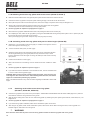
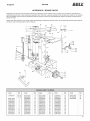
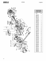
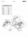
English SPV26 MANUAL FOR USE AND MAINTENANCE SPV26 GB © 1996 BELL - FORM. D22000076 - ver.2 1 SPV26 English TABLE OF CONTENTS INTRODUCTION ....................................................................................................................................................................................... 3 1 DESCRIPTION OF THE MACHINE ......................................................................................................................................................... 3 1.1 Symbols used ............................................................................................................................................................................... 4 2 TECHNICAL DATA ................................................................................................................................................................................... 5 3 SAFETY .................................................................................................................................................................................................... 3.1 General safety regulations ........................................................................................................................................................... 3.1.A For machines with electric motor ................................................................................................................................................. 3.1.B For machines with fuel engine ..................................................................................................................................................... 3.1.C For machines with connection to the hydraulic system of the tractor (IT) .................................................................................. 3.1.D For machines with pump on the tractor power take-off (GI) ........................................................................................................ 3.1.E For machines driven by cardan shaft (GC) .................................................................................................................................. 6 6 7 7 7 7 7 4 OPERATING THE MACHINE FOR THE FIRST TIME ............................................................................................................................ 4.1.A For machines with electric motor ................................................................................................................................................. 4.1.B For machines with fuel engine ..................................................................................................................................................... 4.1.C For machines with connection to the hydraulic system of the tractor (IT) .................................................................................. 4.1.D For machines with pump on the tractor power take-off (GI) ........................................................................................................ 4.1.E For machines with pump on the tractor power take-off (GC) ...................................................................................................... 4.2 Lighting ......................................................................................................................................................................................... 8 8 8 8 9 9 9 5 USE 5.1.A 5.1.B 5.1.C 5.2 5.3 5.4 5.5 5.6 6 ROUTINE MAINTENANCE ....................................................................................................................................................................... 13 6.1 How to clean the oil filter .............................................................................................................................................................. 13 6.2 How to change the hydraulic oil ................................................................................................................................................... 13 6.3 Sharpening the wedge ................................................................................................................................................................. 14 7 TROUBLESHOOTING .............................................................................................................................................................................. 14 7.1 Resetting of the thermal cut-out of the electric motor ................................................................................................................. 14 ...................................................................................................................................................................................................... 10 Switching on/off of the log splitter with electric motor (SPV26-E SPV26-T) .............................................................................. 10 Switching on/off of the log splitter with petrol or diesel engine (SPV26-BS) .............................................................................. 10 Switching on/off of the tractor-driven log splitter (SPV26-IT, SPV26-GC, SPV26-GI) ............................................................... 10 How to use log splitter .................................................................................................................................................................. 11 Movable work surface .................................................................................................................................................................. 11 How to adjust blade stroke ........................................................................................................................................................... 11 How to transport the log splitter ................................................................................................................................................... 12 Assembly and use of the 4-way wedge ....................................................................................................................................... 12 DISMANTLING OF THE LOG SPLITTER ................................................................................................................................................ 14 GUARANTEE ............................................................................................................................................................................................ 15 APPENDIX A - WIRING AND HYDRAULIC DIAGRAMS ........................................................................................................................ 16 APPENDIX B - SPARE PARTS ................................................................................................................................................................ 17 I WARNING When the machine is delivered, check for any missing parts and for any damage during transport. Any complaints must be forwarded immediately to the carrier and to the retailer. Any subsequent complaints will not be accepted. 2 SPV26 English INTRODUCTION BELL® log splitters have been designed and manufactured in compliance with the most recent European safety regulations with particular reference to the EN609 and UNI60204 standards. The ZHB control systems have been designed and engineered so that the operator is forced to work in the safety area without any possibility of inserting hands or arms in dangerous areas. Before transporting, installing or operating the machine, read all parts of this manual, paying particular attention to the specific safety regulations. Operators who are unable to understand any of the languages in which this manual is written are responsible for asking the retailer to provide a manual in their own language. The operator must also train any other person authorised to use the machine. Failure to comply in any way with these instructions, improper use of the machine, extraordinary maintenance operations not carried out by skilled, authorised personnel, removal of data plates or markings of any type, removal or tampering with the guards and safety mechanisms of the machine or any other action not expressly authorised that may impair the active and passive safety systems of the machine shall relieve the manufacturer of all and any liability and may result in serious injury and damage. If the machine is tampered with in any way by unauthorised personnel, the guarantee is automatically null and void. This manual is an integral part of the machine and must accompany it even in the case of transfer of ownership. DESCRIPTION OF THE MACHINE The SPV26 vertical, transportable log splitter is equipped with its own electric motor or petrol or diesel engine or with an external connection for powering by a tractor. The various parts of the machine are shown in fig. 1. Carrying handle Splitting length adjustment ZHB control levers Current socket Fig. 1 Machine parts Wedge Telescopic mast Work surface Main switch Control valve Oil tank Oil plug Motor (electric motor in the figure) Wheels for minor movements NOTE: Only the SPV26 log splitter with electric motor is shown in fig. 1. The configuration of the other models with different drive system varies. PERMITTED AND MANDATORY WORK AREA 3 SPV26 1.1 - Symbols used Standard graphic symbols are used on all machines in order to ensure complete safety of all parts of the log splitter. As these symbols are very important, read the information below attentively. it is obligatory to read the machines use and maintenance manual in full before using the machine. Warning: direction of rotation of the wedge. Never touch the wedge or the supporting arm when in movement. in normal conditions of use, our machines may expose the operator daily to noise levels lower than or equal to 85 dB(a). it is therefore obligatory to wear ear defenders. Danger of cutting or crushing of the hand: never touch hazardous areas while the wedge is moving. it is obligatory to wear safety footwear at all times to provide protection against the risk of logs accidentally falling on feet. Warning: never remove a log trapped in the wedge with your hands. it is obligatory at all times to wear gloves which protect the hands against chips and splinters which may be produced during work. Warning: voltage as indicated on the rating plate it is obligatory at all times to wear a helmet which protects the hands against chips and splinters which may be produced during work. Danger of burns: very hot surface. Do not touch. it is obligatory at all times to wear goggles or a visor which protects the hands against chips and splinters which may be produced during work. it is forbidden to remove or tamper with the protection devices and safety devices. it is forbidden to carry out any maintenance work or to renew parts on the machine when it is running. it is forbidden to smoke near the machine and in the work area. it is forbidden to stand in the range of action of the machine. apart from the operator, no other person or animal may be present within a radius of 5 metres from the machine. Dumping of used oil in the environment is forbidden. The oil must be disposed of according to current legislation in the country where this operation is carried out. 4 Direction of rotation of the motor. If the motor runs in the wrong direction, follow the instructions given in paragraph 4.1 on page 8. make certain that the gearbox shaft rotates in an anticlockwise direction and does not exceed 540 rpm. make certain that the gearbox shaft rotates in a clockwise direction and does not exceed 540 rpm. English SPV26 English 2 - TECHNICAL DATA 7(&+1,&$/'$7$639 ( 7 %6 ,7 *, *& Lenght (mm) 620 620 620 730 730 790 Widht (mm) 730 730 730 730 730 730 Height (mm) 1760 1760 1760 1760 1760 1760 Weight (Kg) 152 152 147 126 108 156 Max. working pressure (bar) 180 180 180 180 180 180 Max. force (tons.) 8 8 8 8 8 8 Log capacity (mm) 1050 1050 1050 1050 1050 1050 8,3 8,3 8,3 8,3 8,3 8,3 hydraulic oil tank capacity (Lt.) 6 6 6 6 6 6 Huydraulic oil total capacity (Lt.) 9 9 9 9 9 9 230V 50Hz Single-ph. 230V 50Hz 3-ph. 400V 50Hz 3-ph. Premium grade fuel From tractor hydraulic system 15,6A 230V 3-ph.: 16,1A 400V 3-ph.: 9,3A ----- ----- ----- ----- 3Hp - 2,2KW 4Hp - 3KW 5Hp ----- ----- ----- Pump capacity (cc/round) Supply Absorption Power Pump on Pump for cardan power take-off shaft Noise £ 85 dB(A) measured at the height of the operators ear in the working position with the log splitter in operation · · The ears must be suitably protected (ear defenders). If the log splitter is connected to a tractor, machine noise is amply covered by that of the tractor. Recommended oils We recommend use of the following oils for the hydraulic cylinder: SHELL TELLUS T22 ARAL VITAM GF22 SP ENERGOL HCP22 MOBIL DTE11 or equivalent DO NOT USE OTHER GRADE OILS. Fig.2 Maximum size of the log to be split For the type of oil to be used with the SPV26-BS model with petrol or diesel engine, refer to the engine manufacturers recommendations given in the related booklet. 5 SPV26 English 3 - SAFETY The information given in the chapter is extremely important for safety purposes. It describes possible hazards tied to use of the machine and instructions for correct use of this to avoid injury or damage. WARNING: The BELL Mod. SPV26 log splitter has been designed and manufactured to split logs of the sizes recommended on page 5 only. Use of the machine for any other purpose shall be considered improper and the manufacturer shall not be liable for any injuries or damage to be ascribed to improper use of the machine. The operator must work in the position shown in fig. 1 only and operate the machine drive control with both hands without using other makeshift systems and without tampering with the ZHB control. When the machine is working, persons and animals must be kept at a distance of at least 5 meters from the machine. NEVER ATTEMPT TO TAMPER WITH THE PROTECTIONS OF THE LOG SPLITTER OR TO OPERATE THE MACHINE WITHOUT THESE. FAILURE TO COMPLY WITH THE INSTRUCTIONS GIVEN IN THIS CHAPTER MAY RESULT IN SERIOUS INJURY OR DAMAGE TO PERSONS, THINGS AND TO THE MACHINE. 3.1 - General safety regulations · · · The machine must always be used by one operator only. Nobody must be allowed to use the log splitter unless they have read the instruction manual and have been instructed in the regulations to follow for correct and safe use. The machine must be used by adults only. Use of the log splitter by apprentices of not less than 16 years of age must be supervised by an adult authorised to use the machine. · Never wear loose, unbuttoned clothing which may become trapped in moving parts. · Do not move the log splitter while the motor is running. · · · · Do not work on sloping or slippery ground. position the machine in a flat area free from objects which may impede the freedom of movement of the operator. Check that the logs to be split are free from nails or wire, which may fly up or damage the machine. the ends of the logs must be cut square. branches must be cut off flush with the trunk. Never try to split logs larger than those indicated in fig. 2. This could be dangerous and may damage the machine. Break wood in the direction of the grain. do not place wood across the log splitter and leave it in that position for splitting; it may be dangerous and may seriously damage the machine. · Never attempt to cut two logs at once; one may fly up and hit you. · If the log moves away from the blade, retract the ram or the blade and turn the log through 90°. · Do not attempt to load the log in the log splitter while the ram is in motion. you could get trapped and injured. · · · · Keep your hands well away from any splits and cracks which open in the log; these may close suddenly and crush or amputate your fingers. Do not force the log splitter for more than 30 seconds by keeping the cylinder under pressure at the end of its stroke, or by persisting when a log does not split or gets stuck on the blade. Oil under pressure overheats very rapidly, damaging the pump. Never leave the machine unattended while it is running. If you leave the machine, even for a short time, remove the power supply or any possible cause of accidental start-up. The log splitter must never be used by an operator who is under the influence of alcohol, drugs, medicines, or who is tired. A clear mind is essential for safety. · Never try to release a jammed log while the machine is running. The machine must be switched off during this operation. · Never request the assistance of another person to help you remove a jammed log. 6 English SPV26 3.1.A - For machines with electric motor... · · · do not use machines with electric motor if natural gas, petrol fumes or other inflammable vapours are present. check that the electric circuit is adequately protected and that it corresponds with the power, voltage and frequency of the motor; check that there is a ground connection, and a regulation differential switch upstream. Use cables with a section of 2.5 mm2. Avoid use of free and inadequately insulated connections. Connections must be made with protected material suitable for outdoor use. · Make sure that the machine and the cable never come in contact with water. · to prevent accidental start-up, ensure that the switch is off before plugging in the power cable. · · treat the power cable with care. do not attempt to move the machine by pulling the cable. do not yank the cable to unplug it; keep the cable away from excessive heat, oil and sharp objects. never leave the machine unattended with the power supply on. also disconnect the power cable when not in use, when carrying out maintenance work, when changing attachment or moving the machine. 3.1.B - For machines with fuel engine... · take the necessary precautions against fire when working in dry areas. · do not smoke while working or refuelling. · · never refuel the log splitter while it is running. switch the engine off and leave it to cool. fill with fuel taking care that the tank does not overflow. wipe off any traces of petrol before starting up. Handle fuel with care. Never touch the engine or the exhaust pipe as they become very hot and may cause burns. I WARNING DO NOT START THE ENGINE IN AN ENCLOSED SPACE; EXHAUST FUMES ARE LETHAL. 3.1.C - For machines with connection to the hydraulic system of the tractor (IT) · Never connect the log splitter with the tractor moving. · Use only fast-disconnect hydraulic fittings, of the correct size and always check that they are correctly fastened and tight. 3.1.D - For machines with pump on the tractor power take-off (GI) · Never connect the log splitter with the tractor moving. · Always check that the gearbox is correctly inserted in the tractor PTO. · · · Fasten the gearbox to the tractor with suitable chains. A short chain may break with consequent injury to persons and damage to the machinery. Never touch the power take-off when the engine of the tractor is running. This can be very dangerous. Interrupt work immediately and stop the tractor in the case of any leaks of oil from the pipes or gearbox. The tubes are under pressure and any cracks or breaks may be extremely dangerous. 3.1.E - For machines driven by cardan shaft (GC) · Never connect the log splitter with the tractor moving. · Make sure that the machine is properly fixed to the 3 points of the tractor. · Make sure that the cardan shaft is fully inserted in the power take-off and has clicked in place. · Never touch the cardan shaft with the engine running. 7 SPV26 English 4 - OPERATING THE MACHINE FOR THE FIRST TIME Never use the log splitter if it is not in perfect order or if it needs servicing. Before starting work, check correct functioning of all the safety devices (ZHB, switch-off button on electric machines). Before starting work, check the level of the hydraulic oil in the tank and top up if necessary with one of the oils indicated on page 5. The level of the oil must be between the two notches on the rod of the oil plug. Fig.3 Before starting work, switch on the log splitter and let the oil warm up for a few minutes. Oil level After 200 hours of use, clean the oil filter as explained on page 13 paragraph 6.1 before starting the machine. 4.1.A - For machines with electric motor... If the motor does not run in the correct direction, invert two of the phases in the socket. Remove the plug from the log splitter. Insert a slotted screwdriver with a suitably sized wedge in the slot located in the connection inlet close to the electric motor as shown in figure 4. Exerting a slight pressure, turn the white wheel by 180°. This operation physically inverts the poles on the three-phase motor. Check that the motor runs in the correct direction as indicated by the arrow. I Never open the box containing the switch, or open the terminal block on the motor. if it is necessary to do so, have these operations carried out by your electrician. If the fuses blow or the protection valve trips, this means that you are overloading the motor or the electrical installation is not correctly rated. Consult your electrician. Fig.4 Inversion of the poles in the threephase motor 4.1.B - For machines with petrol or diesel engine... Before operating the log splitter, carefully read the users manual for the engine fitted. study the maintenance regulations and guarantee supplied. Check the oil level in the engine block. top up if necessary. WARNING: working without oil causes irreparable damage. When the engine is new, it is important, at first start-up, to let it turn over without performing any work for at least twenty minutes. this runningin period ensures maximum performance and smooth operation of the whole system. 4.1.C - For machines with connection to the hydraulic system of the tractor (IT) · · · · · · · 8 Make sure the tractor is off, that the parking brake is on and if necessary that the wheels are chocked. Before starting work, always check that none of the hydraulic tubes is damaged. Connect the oil delivery tube (marked with a special flat white clip) of the log splitter and the discharge tube (no marking) to the hydraulic system of the tractor. Make certain that all unions are tight and that there is no leakage of oil. Apply a pressure not exceeding 220 bar to the hydraulic circuit of the log splitter. Perform a few cycles without wood before starting work so as to vent any air present in the hydraulic circuit. When disconnecting the machine from the hydraulic system of the tractor, take care not to spill any oil, and to replace the plugs on the two tube unions. SPV26 English 4.1.D - For machines with pump on the tractor power take-off (GI) · · · · · · Make sure the tractor is off, that the parking brake is on and if necessary that the wheels are chocked. Insert the gearbox (fig. 5) directly in the tractor power take-off. Fasten the two flanges of the gearbox to the two points of the tractor using appropriately sized chains (fig. 6) making sure they are firmly fastened. During use of the log splitter, a very high turning force is applied at this point (more than 200 Kg) Incorrect fastening could cause serious injury and damage. Before starting work, check the hydraulic tubes for any damage and make sure there is oil in the box of the gearbox. Working without oil may cause irreparable damage. Fig.5 Inlet for power take-off. Make certain that the power take-off runs in the direction indicated on the gearbox. Position the accelerator at a suitable rpm for your tractor so that the engine provides sufficient power for correct functioning of the log splitter and check that the power take-off does not exceed 540 rpm as shown on the data plate (see page 4, par. 1.1 SYMBOLS USED I WARNING Follow the few very important rules indicated above to avoid problems that could cause injury or damage. 4.1.E - For machines driven by cardan shaft (GC) · · · · · Make sure the tractor is off, that the parking brake is on and if necessary that the wheels are chocked. Connect the log splitter to the three points of the tractor. Connect the cardan shaft to the gearbox (fig.7 to the power take-off of the tractor. The cardan shaft must be of suitable length and complete with protective cover. Check that it clicks into place. After connecting the log splitter, start the tractor and check that the cardan shaft turns in the direction indicated on the data plate on the gearbox (see par. 1.1 SYMBOLS USED on page 4). Fig.6 Connection of the power take-off to contrast rotation. Position the accelerator at a suitable rpm for your tractor so that the engine provides sufficient power for correct functioning of the log splitter and check that the power take-off does not exceed 540 rpm as shown on the data plate (see page 4, par. 1.1 SYMBOLS USED I WARNING I WARNING Follow the few very important rules indicated above to avoid problems that could cause injury or damage. Never touch the cardan shaft or any other rotating parts. This is extremely dangerous and may cause injury or damage. Fig.7 Connection of the cardan shaft 4.2 - Lighting Lighting must be provided in the entire work area of the log splitter to ensure perfect visibility when operating the machine and during maintenance and adjustments. Even when working outdoors, there must be sufficient light to work safely. Working at times when insufficient light may result in poor visibility of the machine and its components (dawn, dusk, night) is forbidden. 9 SPV26 English 5 - USE 5.1 A Switching on/off of the log splitter with electric motor (SPV26-E, SPV26-T) · · · · · · · Make sure that the switch/cutout of the general power system and the switch of the machine are OFF. Connect the electric log splitter to the power system inserting the plug in the socket on the electric motor. Never pass the power cable over the telescopic mast, close to the wedge or anywhere where it may be damaged or cut. Set the main on/off switch and then press the switch in the green area to start the log splitter. The telescopic mast will move automatically to the fully open position. Use the log splitter as explained in paragraph 5.2 on page 11. Never leave the log splitter unattended without first of all pressing the switch in the red area (off). On completing the work, switch off the log splitter by turning the switch/differential of the general power system to the 0 position (off) and then remove the plug from the socket on the machine. Never yank the plug using the cable. Grasp the body of the plug and pull it firmly. 5.1.B - Switching on/off of the log splitter with petrol or diesel engine (SPV26-BS) · · · · · · · Switching on: Turn the throttle control knob (upper) to CHOKE if the engine is cold or to RUN if the engine is still warm (fig. 8) Turn the accelerator knob (lower) to IDLE (fig.8) Grasp the engine start-up knob and holding it tightly pull it firmly. Repeat this operation until the engine starts (fig.9). During this phase, be very careful not to slip or cause injuries or distortions. Once the engine is running, the telescopic mast moves to the fully open position. Position the accelerator to FAST (fig.8) After a few minutes from cold starting, move the throttle control from CHOKE to RUN (fig.8) Fig.8 Accelerator positions Use the log splitter as explained in par.5.2 on page 11 If you leave the machine unattended or have finished the work, turn the accelerator knob to OFF to switch off the log splitter (fig.8). WARNING: When working and after switching off the log splitter, never touch any part of the engine as this could cause burns. After switching off the machine, wait until the engine has cooled before performing any operation. Refer to the attached manual for any other information regarding the BRIGGS & STRATTON engine. Fig.9 5.1.C · · · · · Petrol or diesel engine start-up Switching on/off of the tractor-driven log splitter (SPV26-IT, SPV26-GC, SPV26-GI) Connect the log splitter to the power source (see chapter 4 OPERATING THE MACHINE FOR THE FIRST TIME pages 8 or 9) and then check that the machine is firmly positioned on the ground. Start the tractor making sure it does not move. Start the log splitter by activating the power system (power take-off, cardan shaft, etc.). The wedge will lift. Use the log splitter as explained in paragraph 5.2 on page 11. If you leave the log splitter unattended, switch off the transmission system of the tractor. After using the log splitter, switch off the transmission system, switch off the tractor. Before moving the tractor, lift the log splitter to a sufficient height so that it does not hit the ground. I WARNING Never move the tractor with the power source of the log splitter activated or with the log splitter still on the ground. 10 SPV26 English 5.2 · · How to use log splitter Place the log on the work surface as shown in fig.10 making sure it is centered under the wedge. The two faces of the log must be parallel to each other and to the work surface to guarantee safe operation. Working in the mandatory position only (fig. 1 page 3), grasp the log with the levers of the ZHB control so that the jaws penetrate slightly into the bark and then lower the levers (fig.11/a); the wedge will start to cut into the log. Note: As soon as the wedge starts to split the log, widen the arms of the ZHB control slightly (fig.11/b) continuing to press the levers down so that the force applied does not damage the jaws. · · If the log does not split quickly or if the wedge stops, do not keep the machine under force. Then hydraulic oil overheats very quickly with damage to the pump. It is advisable to return the mast to the idle position and to make another attempt after rotating the log. Repeat the operation with the pieces obtained so as to split the log into several parts. Note: If you let go of even just one of the levers, the machine will stop in the position reached. If you let go of both levers, the telescopic mast will move to the fully open position. Fig.10 Fig.11/a Two-hand control Positioning of the log on the log splitter Fig.11/b Two-hand control 5.3 - Movable work surface The movable work surface (1 in fig.12) allows the log capacity adjustment in relation to the log lenght. The plane placed in A position allows to split logs until 72 cm. lenght. With the plane placed in B position the logs lenght increases until 105 cm., but only until the wedge stroke. Fig.12 Movable work surface 5.4 - How to adjust blade stroke To save time, a system has been designed that makes it possible to adjust wedge travel so that this can be set for short logs. In this way, the wedge travels for the distance required only. After checking the length of the longest logs to be split, regulate wedge travel as follows: · · · · Start the log splitter and bring the wedge to the position required. Release one of machine control levers so that the wedge stops in the selected position. Back off knob 1 in fig. 13 with the other hand. Pull the rod (2) up until it locks in place. Draw up the knob (1) again making sure it is tight. The log splitter will now reposition at the point selected. Fig.13 Blade travel adjustment 11 SPV26 English 5.5 - How to transport the log splitter The Mod. SPV26 log splitter must be transported with the wedge mast fully retracted in the body. Use the carrying handle on the top part of the mast (fig. 15) for safe, trouble-free transport of the log splitter. · · Rest one foot on the base of the log splitter. Pull the handle, tilting the machine towards you to facilitate transport (fig. 14). To rest the machine on the ground, put one foot on the base and lower the machine carefully. Fig.14 How to lift the log splitter Fig.15 How to transport the log splitter 5.6 - Assembly and use of the 4-way wedge (optional K91000000) The SPV26 model vertical log splitter can be equipped on request with a 4-way wedge to split a trunk into four logs with a single stroke. The 4-way wedge (A in fig. 16) must be assembled directly on the standard 2-way wedge (B). Position the 4-way wedge so that it is in contact with pin (C) and fasten it in place by tightening the butterfly screw (D) which must engage in hole (E) in the 2-way wedge (fig. 17). This wedge is used in the same way as the 2-way wedge taking care, however, not to split very hard wood or wood with a large number of knots as the use of 2 wedges instead of 1 causes greater stress on the wedge. Fig.16 Assembly of the 4-way wedge Fig.17 12 Engagement of the lock screw English SPV26 6 - ROUTINE MAINTENANCE This chapter describes routine maintenance, i.e. operations carried out by the operator, on the SPV26 log splitter to keep this in perfect working order and therefore reliable for continuous, long-term use. All routine maintenance operations must be carried out with the machine off and in the case of log splitters with electric motor with the power cable disconnected. Any other maintenance operation not specifically envisaged in this manual must be carried out by authorised personnel only in that hazardous situations may arise for which the operator is not prepared. In the case in which extraordinary maintenance or part replacement operations are not carried out by authorised personnel, the guarantee shall be immediately null and void and the manufacturer shall be relieved of any responsibility for injury to persons or animals or damage. 6.1 - How to clean the oil filter To keep the machine in perfect working order, the oil filter of the hydraulic system must be thoroughly cleaned every 300 hours of operation. · · · · · Loosen the hose clamp (1 in fig.18) and take off the hose from the lead of the filter support. Unscrew the three screws (2) by using an allen wrench then extract the filter group giving care to the gasket (2 in fig.19). Remove the filter (4) from its support (1) using an exagonal wrench, holding on the point 3. Wash the filter with petrol and, if possible, blow it with compressed air. Screw again the filter (4) on the support (1). Inserting the filter group in its seat, placed in the oil tank, paying attention to the correct position of the gasket (2). Lock the filter group with the three previously taken off screws. Joint the hose then lock it by the clamp. Fig.18 Extraction of the oil filter 6.2 - How to change the hydraulic oil The spent oil must be replaced with new oil of the type indicated on page 5 every 600 hours of operation. To change the oil, proceed as follows. · · · · · Make sure that the mast of the machine is fully retracted (wedge closed). Fig.19 Disassembly of the oil filter. 3 Raise the log splitter slightly and rest it on two chocks (2 in fig.20). Place a receptacle (fig.20) able to hold around 10 Lt. of oil under the oil drainage plug located to the rear of the machine. Unscrew the drainage plug (pos. 1 figures 20 and 21) with a suitable wrench and let all the oil in the tank drain into the receptacle. 1 2 Once the tank is empty, clean the inlet, the copper washer and the drainage plug with petrol and then replace the drainage plug, drawing this up tightly. Remember to insert the washer (fig.21). Fig.20 Position of the oil recovery tray The oil tank holds around 9 Lt. of oil. · · · · · Remove the oil plug (3 in fig.20) and fill the tank with the correct oil (see page 5 for oils to be used), pouring in around 6 Lt. Switch on the log splitter and activate the telescopic mast for 1/3 of its complete travel. Lower the wedge completely and add the remaining oil. Run the machine for two complete cycles to bleed any air from the hydraulic circuit. Use the oil rod (fig. 3 page 8) to check the right quantity of oil. Clean the inlet of the oil plug and replace the plug. 1 I WARNING: Fig.21 Removal of the plug NEVER MIX OIL WITH GENERAL WASTE! USED OIL MUST BE DISPOSED OF ACCORDING TO CURRENT REGULATIONS IN THE COUNTRY WHERE THE MACHINE IS USED. 13 SPV26 English 6.3 - Sharpening the wedge After long periods of operation and when required, sharpen the wedge of the log splitter using a fine-toothed file and taking care to remove any burrs or crushed parts of the metal. NOTE: For routine maintenance of the petrol or diesel engine (for model SPV26-BS), refer to the related attached booklet. 7- TROUBLESHOOTING Problems that may arise when using the log splitter and recommended remedies are given in the table below. In the case of operations carried out by unauthorised personnel, the guarantee will be immediately null and void and the manufacturer will be relieved of any responsibility for injury to persons and animals and damage. Problem Log fails to split Probable cause Corrective action Hydraulicpressure too low Contact your dealer Oil leack Locate the leack using a piece of card or wood. Contact your dealer Wedge do not cut Sharped the wedge, check for burrs or nicks, file if necessary Incorrect positioning of the log Change the position of the log in relation to the wedge Log exceeds permitted dimensions Try to cut a small part or use other means to reduce the size of the log Air in the circuit Check oil level.Top up if necessary If problem remain contact your dealer Rod advances jerkily or with strong vibrations Unions not properly tight Tighten unions Oil leak from the unions, pump or cylinder Seals worn Contact your dealer 7.1 - Resetting of the thermal cut-out of the electric motor In the case of machines with electric motor, a protection device applied to the motor and integrated in the main on/off switch is tripped in the case of overloads, sudden increases in voltage or accidental faults in the electrical system. In this case, before calling your authorised service centre, wait a few minutes and then try to reset the main on/off switch. If the problem does not re-occur, the log splitter can be used normally. If the cut-out is tripped again, do not try to reset it and contact your ahthorised service centre. DISMANTLING OF THE LOG SPLITTER The log splitter must be dismantled complying with all safety regulations, designed to prevent injury and damage. All parts of the log splitter must be scrapped and disposed of according to current legislation where the machine is dismantled. Pay particular attention when eliminating hydraulic oil which must not be disposed of in the environment in that it is highly pollutant and must be disposed of according to legal prescriptions. 14 English SPV26 GUARANTEE The company BELL, referred to hereinafter as BELL, guarantees to the purchaser of every new BELL original product, purchased from a BELL authorized dealer, that the product shall remain free from any defects in materials or workmanship for a period of 360 days (12 months) from the original date of purchase or the date of first hire. Spare parts installed on the product covered by this guarantee are guaranteed for 90 days (3 months) from the date of their repair or renewal. Such parts must be supplied free of charge to the user by a BELL dealer or distributor during normal working hours. BELL reserves the right to inspect any product or part which has been substituted as defective. Substituted parts must therefore be kept available for 12 months. It is expressly understood that BELL shall be under no obligation to provide labour or accept transport expenses. BELL shall accept no responsibility for any damage, defect or costs deriving from repairs and/or modifications of a BELL product, effected by any person other than an authorized BELL representative. This guarantee does not apply to commercial components covered by their own guarantee, such as internal combustion engines, diesel engines, etc.. This guarantee covers only defects arising during proper use of the machine. BELL shall accept no responsibility whatsoever if BELL components break while under guarantee for reasons such as: 1) 2) Misuse, negligence, improper handling, abuse or accident. Failure to carry out reasonable or necessary maintenance as prescribed in this manual (renewal of worn components such as slides, hydraulic oil, engine oil, gearbox oil; blade not sharpened, etc.) 3) The use of parts or accessories not manufactured, supplied or approved by BELL. BELL does not provide further explicit or implied guarantees, other than those set forth herein. No representative or dealer is authorized to assume other responsibilities with regard to BELL products. The duration of the implicit guarantees recognized by the law, including the commercial guarantees and conventions for particular purposes are limited in duration to the validity and duration of the explicit guarantee granted below. BELL shall upon no account act as guarantor for loss of profit, whether direct or indirect, specific or deriving from any damage. To validate this guarantee, the seller must complete and return within ten (10) days of the date of sale, or the date of hire, the guarantee registration card supplied with each unit sold. If you require spare parts or repair work it will be useful the followins informations: MODEL ............................................................................................................. SERIAL NUMBER ............................................................................................ DATE OF PURCHASE ..................................................................................... 15 SPV26 English APPENDIX A - WIRING AND HYDRAULIC DIAGRAMS I WARNING The following is reserved solely for the authorised personnel of the retailer. The manufacturer declines any responsibility for damage or injury of any kind ensuing to persons, animals or objects due to improper or unauthorised use of this documentation. HYDRAULIC DIAGRAM SINGLE-PHASE ELECTRIC DIAGRAM 16 1 Cylinder 2 Control valve 3 Max. pressure valve 4 Motor 5 Pump (2cm3/round) 6 Tank THREE-PHASE ELECTRIC DIAGRAM SPV26 English ZHB CONTROL Code D05410190 E27150090 E26760012 E26310151 D05410310 E26451200 E26075104 E26561344 E26760014 D05410300 B41080060 E26840014 B07000020 B73200020 B82760020 E26401106 B71100100 B71010350 E28560020 B71010260 B71010270 E26770160 B71010240 D05000550 E51436044 B71010230 D05000540 E28560200 E26150096 E26513038 D05000560 E26075107 B73200010 E26075106 B41000300 E26114068 E26075102 22 Ref. 1 2 3 4 5 6 7 8 9 10 11 12 13 14 15 16 17 18 19 20 21 22 23 24 25 26 27 28 29 30 31 32 33 34 35 36 37 http://www.bell.it via De Pisis, 5 - 42100 Reggio Emilia - Italy Tel.+39 0522 505911 - Fax +39 0522 514204 Email: [email protected] a Certified Company according to Quality System DIN EN ISO 9001:2000 Zertifikat 15 100 31581 Dichiarazione di conformità - Conformity declaration - Konformitätserklärung - Déclaration de conformité Verklaring van overeenstemming - Försäkran om överenstämmelse - Overensstemmelseserklæring Erklæring - Vaatimustenmukaisuusilmoitus - Declaración de conformidad - Declaração de conformidade via F. de Pisis, 5 - Reggio Emilia - Italy dichiara che la macchina - declares that the machine - bestätigt hiermit dass die von Ihr hergestellte Maschine - déclare que la machine - verklaart dat de machine - intygar härmed att maskin - erklærer herved at maskinen - bekræfter hermed som firma at have fremstillet denne maskine täten vakuutamme, että laitemme - declara que la máquina - declara que a máquina SPV26 è conforme ai Requisiti Essenziali di Sicurezza e di Tutela della Salute secondo la Direttiva 98/37/CEE e la Norma Armonizzata EN 609-1 (03/99) is in compliance with the essential Security and Health Protection requirements according to the 98/37/EEC Directive and to the harmonised Norm EN 609-1 (03/99) den wesentlichen Sicherheits- und Gesundheitsschutz Erfordernissen entspricht, gemäss der Bestimmung 98/37/EG, und der harmonisierten Norm EN 609-1 (03/99) est conforme au qualités de Sécurité et Protection de la Santé demandées selon la Directive 98/37/CEE, ainsi que selon la Norme harmonisée EN 609-1 (03/99) overeenstemt met de fundamentele veiligheids- en gezondheidseisen zoals die zijn vastgelegd in Richtlijn 98/37/EEG en de geharmoniseerde norm EN 609-1 (03/99) är i överensstämmelse med säkerhets- och hälsokraven enligt EU-direktivet 98/37 och standarden EN 609-1 (03/99). er i overensstemmelse med sikkerhetskravene og helsevernets forskrifter ifølge EU-direktivet 98/37 og standarden EN 609-1 (03/99) svarer til de grundlæggende sikkerheds- og sundhedskrav i henhold til EU-direktivet 98/37/EF og standarden EN 609-1 (03/99) on direktiivin 98/37/EY ja standardin EN 609-1 (03/99) olennaisten turvallisuus- ja terveysmääräysten mukainen. responde a los Requisitos Esenciales de Seguridad y de Tutela de la Salud, en conformidad con la Directiva 98/37/CEE y la norma armonizada EN 609-1 (03/99) é em conformidade com os Requisitos Essenciais de Segurança e de Tutela da Saúde de acordo com a Directriz 98/37/CEE e a Norma Harmonizada EN 609-1 (03/99) Reggio Emilia Il presidente - The president - Der Präsident - Le président - De directeur Verkställande Direktör - Presidenten - Præsident - Pääjohtaja El Presidente - O Presidente 20/11/02 Olmes Ognibene