1
Storport Miniport Driver
Version 1.30
for Windows Server 2003
User Manual
Copyright© 2007 Emulex Corporation. All rights reserved worldwide. No part of this document may be reproduced
by any means nor translated to any electronic medium without the written consent of Emulex Corporation.
Information furnished by Emulex Corporation is believed to be accurate and reliable. However, no responsibility is
assumed by Emulex Corporation for its use; or for any infringements of patents or other rights of third parties which
may result from its use. No license is granted by implication or otherwise under any patent or patent rights of Emulex
Corporation.
Emulex, AutoPilot Installer, BlockGuard, cLAN, FabricStream, FibreSpy, Giganet, HBAnyware, InSpeed, IntraLink,
LightPulse, MultiPulse, SAN Insite, SBOD and Vixel are registered trademarks, and AutoPilot Manager, EZPilot,
SLI and VMPilot are trademarks, of Emulex Corporation. All other brand or product names referenced herein are
trademarks or registered trademarks of their respective companies or organizations.
Emulex provides this manual "as is" without any warranty of any kind, either expressed or implied, including but not
limited to the implied warranties of merchantability or fitness for a particular purpose. Emulex Corporation may
make improvements and changes to the product described in this manual at any time and without any notice. Emulex
Corporation assumes no responsibility for its use, nor for any infringements of patents or other rights of third parties
that may result. Periodic changes are made to information contained herein; although these changes will be
incorporated into new editions of this manual, Emulex Corporation disclaims any undertaking to give notice of such
changes.
Storport Miniport Driver User Manual
Page ii
Table of Contents
Installation .................................................................................................................. 1
Introduction.............................................................................................................. 1
Important Considerations......................................................................................... 1
Changing Driver Types ...................................................................................... 1
Microsoft Storport Driver Update ....................................................................... 1
AutoPilot Installer Terminates with Legacy HBAs Installed ................................ 2
AutoPilot Installer Management Mode Setup..................................................... 2
Storport Miniport Driver Information ......................................................................... 2
Prerequisites ..................................................................................................... 2
Compatibility...................................................................................................... 2
New in This Release ......................................................................................... 3
Known Issues .................................................................................................... 3
Distribution Executable File Overview ..................................................................... 3
Running the Distribution Executable File ........................................................... 3
AutoPilot Installer..................................................................................................... 4
Introduction ....................................................................................................... 4
Prerequisites ............................................................................................... 4
AutoPilot Installer Features ......................................................................... 4
Configuration Questions.............................................................................. 4
Installation Planning .......................................................................................... 5
AutoPilot Installation Procedures ............................................................................. 6
Hardware-First Installation................................................................................. 6
If the Installation Fails ................................................................................. 7
Software-First Installation .................................................................................. 8
Installing the HBAnyware Security Configurator ...................................................... 9
Installing the HBAnyware Utility Web Launch Feature ........................................... 10
Updating the HBAnyware Utility Web Launch URL ................................................ 12
Unattended Installation .......................................................................................... 13
AutoPilot Configuration File Format................................................................. 13
Mandatory Configuration File Changes ........................................................... 14
Deleting Questions in the APInstall.cfg File ..................................................... 14
Optional Configuration File Changes............................................................... 15
Setting Up Driver Parameters.......................................................................... 18
Setting Up System Parameters ....................................................................... 18
AutoPilot Installer Error Codes Reference Table ............................................. 18
Invoking AutoPilot Installer .............................................................................. 19
Batch File Example ......................................................................................... 19
Manually Installing or Updating the Storport Miniport Driver .................................. 22
Overview ......................................................................................................... 22
Removing the Adjunct Driver Registry Key...................................................... 22
Manually Installing the Emulex PLUS (ElxPlus) Driver for the First Time ........ 22
Prerequisites ............................................................................................. 22
Manually Updating the Emulex PLUS (ElxPlus) Driver .................................... 23
Prerequisites ............................................................................................. 23
Manually Installing or Updating the Storport Miniport Driver ............................ 23
Manually Installing the Driver Utilities .............................................................. 24
Prerequisites ............................................................................................. 24
Uninstalling the Utility Package (the HBAnyware utility, Web Launch and the
lputilnt utility) ................................................................................................... 25
Storport Miniport Driver User Manual
Page iii
Table of Contents
Uninstalling HBAnyware Web Launch ............................................................. 26
Uninstalling the Emulex Drivers....................................................................... 27
Configuration ........................................................................................................... 28
Introduction............................................................................................................ 28
Starting the HBAnyware Utility with Web Launch............................................. 29
Starting HBAnyware from the Desktop ............................................................ 29
Changing Management Mode ................................................................... 30
Starting the HBAnyware Security Configurator.......................................... 31
Starting HBAnyware from the Command Line ................................................. 32
HBAnyware Window Element Definitions ........................................................ 33
The Menu Bar ........................................................................................... 33
The Toolbar ............................................................................................... 33
The Toolbar Buttons .................................................................................. 33
Discovery-Tree .......................................................................................... 34
Property Tabs ............................................................................................ 35
Status Bar ................................................................................................. 35
Using the HBAnyware Command-Line Interface ............................................. 35
The CLI Client Command Reference ........................................................ 37
Starting the LightPulse Utility (lputilnt) ............................................................. 53
lputilnt Category Summaries ........................................................................... 53
Discovering HBAs.................................................................................................. 54
Discovering HBAs using the HBAnyware Utility............................................... 54
Configuring Discovery Settings ................................................................. 54
Discovering HBAs Using lputilnt ...................................................................... 55
Resetting the HBA ................................................................................................. 56
Resetting the HBA with HBAnyware ................................................................ 56
Resetting the HBA with lputilnt ........................................................................ 56
Sorting HBA Information ........................................................................................ 57
Sorting HBAs with HBAnyware........................................................................ 57
Sorting by Host Name ............................................................................... 57
Sorting by Fabric Address ......................................................................... 57
Sorting Local HBAs Only with HBAnyware ...................................................... 57
Sorting Local HBAs with lputilnt....................................................................... 58
Downloading PCI Configuration Files with lputilnt ........................................... 58
Viewing HBA Information Using HBAnyware ......................................................... 58
Viewing Discovered Information ...................................................................... 58
Viewing Host Information................................................................................. 59
The Host Information Tab .......................................................................... 59
The Host Driver Parameters Tab ............................................................... 60
Viewing General HBA Information ................................................................... 61
View Detailed HBA Information ....................................................................... 62
Port Attributes Field Definitions ................................................................. 63
Loop Map Table Definitions ....................................................................... 63
Viewing Fabric Attributes................................................................................. 64
Discovery Information Field Definitions ..................................................... 64
Viewing Target Information .............................................................................. 65
Viewing LUN Information ................................................................................. 66
Viewing Port Statistics ..................................................................................... 67
Port Statistics Field Definitions .................................................................. 67
Viewing Firmware Information ......................................................................... 69
Storport Miniport Driver User Manual
Page iv
Table of Contents
Viewing Target Mapping .................................................................................. 70
Viewing Driver Parameters .............................................................................. 71
Viewing Driver Parameters for an HBA ..................................................... 71
Viewing Driver Parameters for All HBAs in a Host .................................... 72
Setting Driver Parameters ..................................................................................... 74
Activation Requirements.................................................................................. 74
Setting Host Parameters Using HBAnyware.................................................... 74
Setting Driver Parameters for a Host ........................................................ 75
Restoring All Parameters to their Earlier Values........................................ 75
Resetting Host Parameters ....................................................................... 75
Setting HBA Driver Parameters Using HBAnyware ......................................... 76
Restoring All Parameters to Their Earlier Values ...................................... 77
Resetting HBA Parameters ....................................................................... 77
Saving HBA Driver Parameters to a File ................................................... 77
Setting an HBA Parameter Value to the Host Parameter Value................. 77
Setting Parameters Using lputilnt .................................................................... 78
Resetting HBA Values ............................................................................... 79
Driver Parameter Reference Table .................................................................. 80
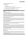
Server Performance .............................................................................................. 86
I/O Coalescing................................................................................................. 86
Performance Testing ....................................................................................... 87
Performance Testing Examples................................................................. 87
Setting Topology .................................................................................................... 88
Topology Reference Table ............................................................................... 88
Setting Topology with HBAnyware................................................................... 89
Setting Topology with lputilnt ........................................................................... 89
Mapping and Masking............................................................................................ 89
Automapping SCSI Devices ............................................................................ 89
Automapping SCSI Devices with HBAnyware ........................................... 89
Automapping SCSI Devices with lputilnt ................................................... 90
Target and LUN Mapping and Masking Using lputilnt ...................................... 90
Overviews ................................................................................................. 90
Mapping and Masking Window Defaults .......................................................... 91
Setting Mapping and Masking ......................................................................... 91
Globally Automapping All Targets ............................................................. 91
Globally Mapping All LUNs........................................................................ 92
Globally Unmasking or Masking All LUNs ................................................. 92
Automapping LUNs for a Target ................................................................ 92
Setting Up Persistent Binding .......................................................................... 93
Setting Up Persistent Binding with HBAnyware......................................... 93
Setting Up Persistent Binding with lputilnt ................................................. 95
Updating Firmware or Boot Code .......................................................................... 97
Updating Firmware or Boot Code with HBAnyware ......................................... 97
Updating Firmware or Boot Code (Batch Mode) with HBAnyware ................. 100
Updating Firmware or Boot Code with lputilnt................................................ 102
Performing Basic Diagnostic Tests with HBAnyware ........................................... 103
Running a Quick Test .................................................................................... 103
Running a POST Test.................................................................................... 104
Using Beaconing ........................................................................................... 105
Starting a Diagnostic Dump ........................................................................... 105
Displaying PCI Registers and Wakeup Information ....................................... 106
Storport Miniport Driver User Manual
Page v
Table of Contents
Running Advanced Diagnostic Tests with HBAnyware......................................... 107
Running Loopback Tests ............................................................................... 108
Running End-to-End (ECHO) Tests ............................................................... 109
Saving the Log File .............................................................................................. 110
Out-of-Band SAN Management ........................................................................... 112
Windows Vista Platforms: Adding the RMServer Program to the Firewall 112
Adding a Single Host ..................................................................................... 116
Adding a Range of Hosts............................................................................... 116
Removing Hosts ............................................................................................ 117
HBAnyware Security............................................................................................ 118
Introduction ................................................................................................... 118
Starting the HBAnyware Security Configurator .............................................. 118
Running the Security Configurator for the First Time/Create the ACG........... 119
Designating a Master Security Client ............................................................ 120
Setting Up and Maintaining Access Control Groups ...................................... 120
Introduction ............................................................................................. 120
Selecting/Deselecting Access Control Group Tab on the MSC ............... 120
Viewing the Access Control Group Tab on a Non-MSC........................... 121
ACG Icons............................................................................................... 122
Running the Configurator for the First Time/Creating the ACG ............... 122
Adding a Server to the ACG.................................................................... 122
Deleting a Server from the ACG.............................................................. 123
Removing Security from All Servers in the ACG ..................................... 123
Generating New Security Keys ............................................................... 123
Restoring the ACG to Its Last Saved Configuration ................................ 123
Accessing a Switch ................................................................................. 124
Setting Up and Maintaining Access Sub-Groups ........................................... 124
Introduction ............................................................................................. 124
ASG Icons ............................................................................................... 125
Creating an ASG ..................................................................................... 125
Reserved Indices - Examples.................................................................. 126
Adding a Server to an ASG ..................................................................... 127
Deleting an ASG ..................................................................................... 127
Restoring an ASG to Its Last Saved Configuration.................................. 127
Editing an ASG ....................................................................................... 127
About Offline ASGs ................................................................................. 129
Backup Masters............................................................................................. 129
Introduction ............................................................................................. 129
Backup Master Eligible Systems ............................................................. 130
Backup Master Tab and Controls ............................................................ 130
Creating a Backup Master....................................................................... 131
Reassigning a Backup Master as the New MSC from the Old MSC........ 131
Reassigning the New MSC from the Backup Master............................... 132
Troubleshooting..................................................................................................... 133
Introduction.......................................................................................................... 133
Event Tracing (Windows Server 2003, SP1 only) .......................................... 133
Event Trace Messages .................................................................................. 134
ELS Log Messages (0100 - 0130)........................................................... 134
Discovery Log Messages (0202 - 0262) .................................................. 136
Mailbox Log Messages (0310 - 0326) ..................................................... 138
INIT Log Messages (0400 - 0463)........................................................... 138
Storport Miniport Driver User Manual
Page vi
Table of Contents
FCP Log Messages (0701 - 0749) .......................................................... 140
Link Log Messages (1302 - 1306) ........................................................... 142
Tag Messages (1400 - 1401)................................................................... 143
NPIV Messages (1800 - 1899) ................................................................ 143
Error Log ....................................................................................................... 144
Viewing the Error Log.............................................................................. 144
Severity Scheme ..................................................................................... 144
Related Driver Parameter: LogError........................................................ 144
Format of an Error Log Entry .................................................................. 145
Troubleshooting Topics ........................................................................................ 149
General Situations......................................................................................... 149
Security Configurator Situations - Access Control Group (ACG) ................... 150
Security Configurator Situations - Access Sub-Groups (ASG)....................... 151
Security Configurator Situations - Backup Masters ....................................... 152
Security Configurator Situations - Error Messages ........................................ 153
Security Configurator Situations - Master Security Client (MSC) ................... 154
Non-Hierarchical and Hierarchical ASG ........................................................ 156
Storport Miniport Driver User Manual
Page vii
Installation
Introduction
AutoPilot Installer® for Emulex® Storport Miniport drivers provides installation options that range from a
simple installation with a few mouse clicks to custom unattended installations that use predefined script
files. AutoPilot Installer is included with Emulex drivers and utilities in Windows executable files that you
can download from the Emulex Web site. Run the distribution executable file to extract all of the software
needed for an installation, then complete the installation using AutoPilot Installer. AutoPilot Installer
allows you to install a driver by any of the following methods:
Hardware-first installation. The host bus adapter (HBA) has already been installed before you
download the Emulex drivers and utilities.
Software-first installation. This installation method allows you to download drivers and utilities from the
Emulex Web site and to install them using AutoPilot Installer prior to the installation of any HBAs. You do
not need to specify the model of the HBA you plan to install. The appropriate drivers and utilities
automatically load when you install HBAs at a later time.
Unattended installation. This installation method allows you to set up AutoPilot Installer to run
unattended from customized scripts. Unattended installation works for both hardware-first and softwarefirst installations. An unattended installation:
•
Enables you to set up one location that contains the distribution executable file. All of the
servers install or update the driver and utilities from that location.
•
Operates from the command line.
•
Operates in silent mode.
•
Creates an extensive report file.
•
Reports any errors.
Replicated installation. This installation method allows you to preload drivers and utilities on a system.
Possible applications include installing a driver and utilities in advance on a system before adding HBAs,
and performing system installations that execute AutoPilot Installer in unattended mode.
Important Considerations
Changing Driver Types
•
If you currently use a driver type different from the one you will install with AutoPilot Installer you
will lose your customized driver parameters, persistent bindings, LUN masking and LUN
mapping when you change driver types. The AutoPilot Installer default parameters will usually
be the best options for the new driver type. You may want to note your current settings before
you install the new driver type. After you have installed the new driver type, you can then update
your customized driver parameters.
Microsoft Storport Driver Update
•
See the Emulex Web site for required updates to the Microsoft Storport driver and Microsoft
HBA API library file.
Storport Miniport Driver User Manual
Page 1
AutoPilot Installer Terminates with Legacy HBAs Installed
•
If any Emulex LP6000 or LP7000 HBAs are installed on the server, the AutoPilot Installer
installation will terminate. It will be necessary to remove the LP6000 and LP7000 HBAs in order to
complete the installation.
AutoPilot Installer Management Mode Setup
•
Parameters in the APInstall.cfg file determine if you can manage HBAs remotely (local and
others) and if you change the remote management options once the utility is installed.
Note: See “Setting Up Management Mode for Attended and Unattended
Installations” on page 17 in the Unattended Installation topic for more
information. These management mode parameters govern both attended
and unattended installations.
Storport Miniport Driver Information
Prerequisites
•
•
One of the following operating systems:
•
Windows Server 2003 running on an x86, x64 or Itanium 64-bit platform
•
Windows Vista running on an x86 or x64 platform
See the Emulex Web site for required updates to the Microsoft Storport driver.
Compatibility
•
The Emulex Storport Miniport driver is compatible with the following FC HBAs:
•
LPe11002, LPe11000 and LPe1150 (minimum firmware version 2.50a6; version 2.70a5 is
required for SLI-3 functionality)
•
LP11002, LP11000 and LP1150 (minimum firmware version 2.10a10; version 2.70a5 is
required for SLI-3 functionality)
•
LP10000ExDC and LP1050Ex (minimum firmware version 1.90a4)
•
LP10000DC and LP10000 (minimum firmware version 190a4)
•
LP1005DC-CM2 (minimum firmware 1.90a5)
•
LP1050 and LP1050DC (minimum firmware version 1.90a4)
•
LP9802DC, LP9802 and LP982 (minimum firmware version 1.90a4)
•
LP9402DC, LP9002DC, LP9002L, LP9000 & LP952L (minimum firmware version 3.92a2)
•
LP8000, LP8000DC and LP850
•
If your HBA has a Dragonfly chip version 2.00 or greater, recommended firmware version 3.93a0.
•
If your HBA has a Dragonfly chip below version 2.00, recommended firmware version
3.30a7.
Note: Refer to LP8000 and LP8000DC Firmware Downloads page on the Emulex Web site
to determine the Dragonfly chip version in use.
•
x86 BootBIOS (minimum x86 BootBIOS version 1.70a3)
•
EFIBoot Version 3.11a4 or higher (64-bit only).
Storport Miniport Driver User Manual
Page 2
New in This Release
•
Emulex Storport Miniport driver support for Microsoft Windows Vista.
•
HBAnyware utility version 3.2 with Out-of-Band (OOB) management capability and diagnostics
including loopback and diagnostics dump. The HBAnyware utility, version 3.2 enables you to
start the HBAnyware utility directly from your Web browser. See page 29 for more information
about the HBAnyware utility with Web Launch.
Known Issues
The following issues have been reported at the time of publication. These issues may not yet have been
verified or confirmed and may apply to another product, such as hardware.
•
Adding an HBA to a system while the HBAnyware utility is running causes the HBAnyware utility
to freeze. To add an HBA while the system is running (commonly called a hot plug), you must
exit the HBAnyware GUI client, insert the HBA, and then re-launch the HBAnyware utility.
•
Some Web browsers will continuously try to reload the HBAnyware utility online help making it
unusable. In this case, disable the Web browser's JavaScript capabilities. Refer to the Web
browser's help for more information.
Distribution Executable File Overview
The distribution executable file self-extracts and copies the following onto your system:
•
AutoPilot Installer
•
Storport Miniport driver
•
ElxPlus driver
•
HBAnyware utility
•
HBAnyware Security Configurator
•
LightPulse utility (lputilnt)
After the distribution executable file runs and the files are extracted, you have two options:
•
Run AutoPilot Installer immediately
•
Run AutoPilot Installer later
Running the Distribution Executable File
To run the distribution executable file:
1. Download the distribution executable file from the Emulex Web site to your system.
2. Double-click the distribution executable file. A window is displayed with driver version
information and Emulex contact information.
3. Click Next to access the Installation Folder window or click Cancel to close the window.
4. The default installation location is displayed. Browse to a different location, if desired. Click
Install to continue the installation.
5. The Progress window is displayed. As each task completes, the corresponding box is
automatically selected.
6. After all tasks complete, a confirmation window is displayed. The Start AutoPilot Installer box is
automatically selected. To start AutoPilot Installer later, clear this box.
7. Click Finish to close the distribution executable file.
Storport Miniport Driver User Manual
Page 3
AutoPilot Installer
Introduction
The Emulex AutoPilot Installer is a Fibre Channel (FC) HBA installation wizard for Windows. The
AutoPilot Installer installs (or updates) Emulex drivers and utilities and configures HBAs, drivers and
utilities.
Prerequisites
•
One of the following operating systems must be installed:
•
Windows Server 2003 running on an x86, x64 or Itanium 64-bit platform - See the
Emulex Web site for required updates to the Microsoft Storport driver
•
Windows Vista running on an x86 or x64 platform.
AutoPilot Installer Features
•
Command line functionality - invokes AutoPilot Installer from the command line using
customized installation scripts
•
Driver and utility updates - installs and updates drivers and utilities
•
Multiple HBA installation capability - installs drivers on multiple HBAs, alleviates the need to
manually install the same driver on all HBAs in the system
•
Driver diagnostics - determines whether the driver is properly operating
•
Silent installation mode - suppresses all screen output (necessary for unattended
installation)
•
Management Mode Setup - Parameters in the APInstall.cfg file determine if you can manage
HBAs remotely (local and others) and if you change the remote management options once
the utility is installed.
Note: See “Setting Up Management Mode for Attended and Unattended
Installations” on page 17 in the Unattended Installation topic for more
information. Management mode parameters govern both attended and
unattended installations.
Configuration Questions
Vendor-specific versions of the Emulex driver installation program may include one or more windows
with questions that you must answer before continuing the installation process.
Storport Miniport Driver User Manual
Page 4
Installation Planning
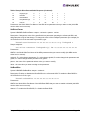
Table 1 describes the types of installations that you can perform under certain conditions. Use this
information to determine which method to use for your situation.
Table 1: Types of Installations
Attended Installations
Condition
HardwareFirst
Installation
No HBA in a single system
SoftwareFirst
Installation
X
Unattended Installations
Unattended
Installation
Replicated
Installation
X
X
New HBA in a single system
X
X
X
Existing HBAs and drivers installed,
updated driver available
X
X
X
X
X
X
X
Multiple systems, no HBAs installed
Multiple systems, new HBAs installed
X
X
Storport Miniport Driver User Manual
Page 5
AutoPilot Installation Procedures
Hardware-First Installation
Prerequisites
•
The Distribution Executable file has been downloaded from the Emulex Web site and extracted
to a directory on your local drive.
Note: To update the Storport Miniport driver, begin the following procedure at step 2.
Procedure
To perform a hardware-first installation:
1. Install a new Emulex HBA and power-on the system. If the Windows Found New Hardware
wizard is displayed, click Cancel to exit. AutoPilot Installer performs this function.
Note: If there are multiple HBAs in the system, the Windows Found New Hardware wizard
appears for each HBA. Click Cancel to exit the wizard for each HBA.
2. If you have already extracted the driver and utility files, run the APInstaller.exe file. If you have
not extracted the driver and utility files, run the distribution executable file (see “Running the
Distribution Executable File” on page 3) and leave the Start AutoPilot Installer box selected.
Click Finish.
3. Click Next. Installation continues.
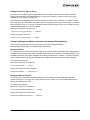
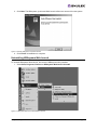
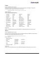
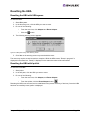
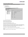
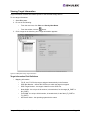
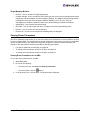
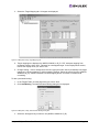
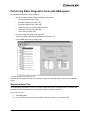
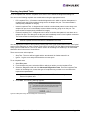
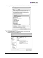
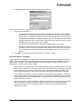
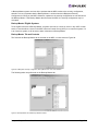
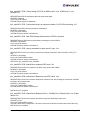
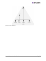
4. Select a management mode. See Figure 1 for three types of host/HBA management.
5. To prevent the management mode from being changed after installation, clear the “Allow users
to change management mode after installing the utility" check box .
Figure 1: AutoPilot Installer Management Mode Setup
Note: The display of the AutoPilot Installer Setup window is optional and based on settings
in the APInstall.cfg file. See “Setting Up Management Mode for Attended and
Unattended Installations” on page 17 for more information.
Storport Miniport Driver User Manual
Page 6
6. Click Next. Installation automatically completes, except in the following situations:
•
If you are changing driver types, the Available Drivers window appears. This window allows
you to select a new driver type. Select the driver type from the drop-down list and click Next.
•
If you are installing an older driver version, the Available Drivers window is displayed. Select
the existing driver version from the drop-down list and click Next.
•
If you are installing a vendor-specific version of the Emulex driver installation program, this
program may include one or more windows with questions that you must answer before
continuing the installation process. In this case, answer each question and click Next on
each window to continue.
7. View the progress of the installation. Once the installation is successful, a congratulations
window appears.
8. View or print a report, if desired.
•
•
View Installation Report - your text editor (typically Notepad) shows a report with current
HBA inventory and configuration information and task results. The text file is named in the
following format: report_MM-DD-YY-#.txt
•
MM = month
•
DD = day
•
YY = year
•
# = report number
Print Installation Report - your default print window is displayed.
9. Click Finish to close AutoPilot Installer. If your system requires a reboot, you are prompted to do
so when you click Finish.
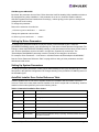
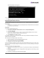
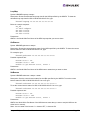
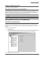
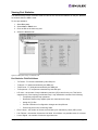
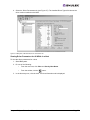
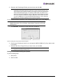
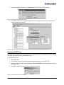
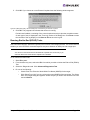
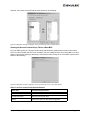
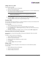
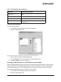
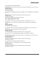
If the Installation Fails
If the installation fails, the Diagnostics window appears. To view the reason an HBA failed, select
the HBA row. The reason and suggested corrective action are displayed below the list.
Figure 2: AutoPilot Installer, Diagnostics Window (Example)
Perform the suggested corrective action and run APInstaller.exe again.
Storport Miniport Driver User Manual
Page 7
Software-First Installation
Prerequisites
•
The Distribution Executable file has been downloaded from the Emulex Web site and extracted
to a directory on your local drive.
Procedure
To perform a software-first installation:
1. If you have already extracted the driver and utility files, run the APInstaller.exe file.
If you have not extracted the driver and utility files, run the distribution executable file (see
page 3), and leave the Start AutoPilot Installer box selected. Click Finish.
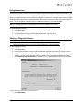
The following message appears:
Figure 3: AutoPilot Installer Message (Software-First Installation)
2. Click OK.
3. The welcome window appears.
4. Click Next. Installation automatically completes.
5. View the progress of the installation. Once the installation is successful, a congratulations
window appears.
6. View or print a report, if desired.
View Installation Report - your text editor (typically Notepad) displays a report with task results.
The text file is named in the following format: report_MM-DD-YY-#.txt
•
MM = month
•
DD = day
•
YY = year
•
# = report number
Print Installation Report - your default print window is displayed.
7. Click Finish to close AutoPilot Installer. If the system needs to reboot, you are prompted to do so
when you click Finish.
Storport Miniport Driver User Manual
Page 8
Installing the HBAnyware Security Configurator
After the HBAnyware utility and remote server are installed on a group of systems, the HBAnyware utility
can remotely access and manage the HBAs on any systems in the group. This may not be desirable
because any system with remote access can perform actions such as resetting boards or downloading
firmware.
The HBAnyware Security Configurator controls which HBAnyware systems can remotely access and
manage HBAs on other systems in an FC network. HBAnyware security is system-based, not userbased. As a result, anyone who can access a system with HBAnyware client access to remote HBAs
can manage those HBAs.
Prerequisites
•
The Storport Miniport driver is installed.
•
The HBAnyware and lputilnt utilities are installed.
Procedure
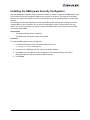
To install the HBAnyware Security Configurator:
1. Locate the SSCsetup.exe file. The default path for this file is:
C:\Program Files\HBAnyware
2. Double-click the SSCsetup.exe file. A welcome window appears.
3. Click Next. The Setup Status window is displayed. After setup completes, the Emulex
HBAnyware Security Setup Completed window appears.
4. Click Finish.
Storport Miniport Driver User Manual
Page 9
Installing the HBAnyware Utility Web Launch Feature
Prerequisites
•
The Storport Miniport driver is installed.
•
The HBAnyware utility is installed.
•
Microsoft Internet Information Services ( IIS) Server is installed. See the Microsoft Web site for
information on downloads and installation.
•
Java Runtime Environment (JRE) is installed. See the www.java.com Web site for information
on downloads and installation.
Procedure
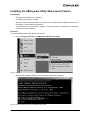
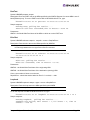
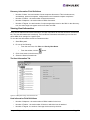
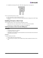
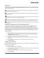
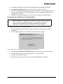
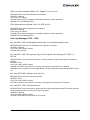
To install the HBAnyware Utility Web launch feature:
1. Click on Programs, Emulex and HBAnyware WebLaunch Install:
Figure 4: HBAnyware Web Launch Installation Shortcut
Web Launch installation begins and the following dialog screen appears:
Figure 5: HBAnyware Web Launch, Initial Installation Dialog Screen
Storport Miniport Driver User Manual
Page 10
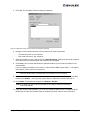
2. Configure the Web server IP address for HBAnyware Web Launch.
a. To configure using the current IP address, type Y.
Figure 6: HBAnyware Web Launch, Installation Dialog Screen After Web Server Listening is Verified
•
To enter your own IP address, type N and enter a new IP address (Figure 7).
Figure 7: HBAnyware Web Launch, Installation Dialog Screen to Enter Another IP Address
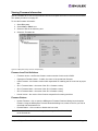
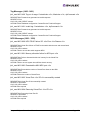
3. Configure the Web server HTTP port for HBAnyware Web Launch.
a. To use the default HTTP <80>, type Y. See Figure 6.
b. To enter a different HTTP port number, type N and enter the HTTP port number.
Figure 8: HBAnyware Web Launch, Web Server Not Listiening on the Normal Default HTTP Port
Storport Miniport Driver User Manual
Page 11
Updating the HBAnyware Utility Web Launch URL
Prerequisites
•
The Storport Miniport driver is installed.
•
The HBAnyware utility is installed.
•
HBAnyware Web Launch is installed.
Procedure
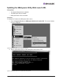
To change the IP address for HBAnyware Web Launch:
1. Click on Programs, Emulex and HBAnyware WebLaunch Update URL. The console window
in Figure 10 appears
Figure 9: HBAnyware Web Launch Update URL Shortcut
2. Type the URL address that you want HBAnyware Web Launch to use.
Figure 10: HBAnyware Web Launch, Update URL Dialog Screen
Storport Miniport Driver User Manual
Page 12
Unattended Installation
Unattended installation is invoked from the command line. The apinstall command uses installation and
driver settings stored in a configuration file (APInstall.cfg). The default APInstall.cfg file is located in the
AutoPilot Installer folder in the Emulex folder in the Program Files directory. Make a copy of the
APInstall.cfg file before you make modifications. The APInstall.cfg file should be used as a starting point
for scripting an unattended installation.
Mandatory configuration file changes:
•
Enabling silent mode
•
Setting up allowable driver types
•
Setting up driver locations
Optional configuration file changes:
•
Changing the utility installation location
•
Setting up an automatic system restart during an unattended Installation
•
Setting up the installation report title and location
•
Setting up an installation without utilities
•
Preventing software-first installations
•
Setting up the existing driver parameter values to be retained or overwritten
•
Setting up the re-installation of an existing driver version
•
Setting up management mode for attended and unattended installation
•
Setting up a Driver Type to Force
Prerequisites
•
The Distribution Executable file has been downloaded from the Emulex Web site and extracted
to a directory on your local drive.
•
It is highly recommended that you make a copy of the APInstall.cfg file and rename it for your
customization.
AutoPilot Configuration File Format
The APInstall.cfg file is organized into commented sections, grouped according to related commands.
•
Lines that begin with a semicolon are comments. To enable sample comment lines, remove the
semicolon.
•
There are five main sections. Three are required and two are optional. Driver parameters must
be set up in the [STORPORT.PARAMS] section. Each section begins with a heading.
•
[AUTOPILOT.ID] - this required section contains revision and label information.
•
[AUTOPILOT.CONFIG] - this required section contains settings that control and configure
the AutoPilot Installer’s operation.
•
[STORPORT.CONFIGURATION] - this optional section may contain questions that must be
answered during the installation process. This section applies to attended installations only.
•
[STORPORT.PARAMS] - this required section can specify driver parameters. Parameters
are read exactly as they are entered and are written to the registry.
•
[SYSTEM.PARAMS] - this section may be created to specify system parameters.
Storport Miniport Driver User Manual
Page 13
Mandatory Configuration File Changes
Locate the Mandatory Configuration File Changes heading in the [AUTOPILOT.CONFIG] section of the
APInstall.cfg file.
Enabling Silent Mode
You may enable silent mode to run an unattended installation. To enable silent mode, remove the
semicolon before:
;SilentInstallEnable = "TRUE"
Setting Up Allowable Driver Types
Four configuration file settings determine what driver types the AutoPilot Installer can install. Remove
the semicolon before:
;win2000DriverPreference
;win2003DriverPreference
;win2000AllowableDrivers
;win2003AllowableDrivers
=
=
=
=
"STORPORT"
"STORPORT"
"STORPORT"
"STORPORT"
Note: All four of these settings must specify the same driver type.
Note: Vista/Longhorn systems automatically use the 'win2003DriverPreference' and
'win2003AllowedDrivers' parameters.
Setting Up Driver Location
In silent mode you need to specify the location of the driver to be installed. Locate the following line in
the APInstall.cfg file:
;LocalDriverLocation = "C:\Path\toThe\Storport\Package"
Remove the semicolon before this line and modify this path to reflect the location of the driver. The driver
location can be a local disk or a network shared drive. It can also be a relative path to the apinstall.cfg
file. The location must be specific to the x86, x64 or IA64 folder to install the correct driver for the server
platform.
Full path example for an x86 driver (all on one line):
LocalDriverLocation = “C:\Program Files\Emulex\AutoPilot
Installer\Drivers\Storport\x86”
Relative path example for x64 driver:
LocalDriverLocation = “Drivers\Storport\x64”
Deleting Questions in the APInstall.cfg File
A [STORPORT.CONFIGURATION] section may exist in the APInstall.cfg file. If this section does exist, it
may contain a [QUESTIONS] section with vendor-specific installation questions. You must remove the
entire [STORPORT.CONFIGURATION] section or comment it out for a silent installation.
Storport Miniport Driver User Manual
Page 14
Optional Configuration File Changes
Locate the Optional Configuration File Changes heading in the [AUTOPILOT.CONFIG] section of the
APInstall.cfg file. This heading follows Mandatory Configuration File Changes.
Changing Utility Installation Location
AutoPilot Installer normally installs utilities from a Utilities subdirectory located in the same directory as
AutoPilot Installer. To modify the location, locate the following in the APInstall.cfg file (all in one line):
; UtilitiesLocation = "C:\Program Files\Emulex\Autopilot
Installer\Windows\Utilities"
Remove the semicolon before this line and modify this directory path to specify an alternate location,
such as a network shared drive.
Setting Up an Automatic System Restart During an Unattended Installation
AutoPilot Installer does not automatically perform system restarts for the following reasons:
•
Restarts often require a login as part of Windows start-up process. If the system is restarted, the
installation process stops until a login is performed.
•
AutoPilot Installer does not know if it is safe to restart the system. Restarts while applications are
active can result in the loss of data.
To configure Windows to start up without requiring a login, remove the semicolon from this line:
; SilentRebootEnable = "FALSE"
Change this parameter to true:
SilentRebootEnable = "TRUE"
Setting Up Installation Report Title and Location
You can change the Installation report name and the location to which it is written. This information must
be specified in one command. In the following example x is the system drive. Remove the semicolon
before:
; ReportLocation = "x: \autopilot\reports\installs\October16-06.txt"
Default File Name
This default file name format is ”report_mm-dd-yy.txt” and uses ‘mm’ for the month, ‘dd’ for the date, and
‘yy’ for the year.
Default Report Location
By default, the report is written to the system drive. In the following example x is the system drive. Your
system drive may be different. You can modify this line to change the report location and/or file name.
" ReportLocation
=
"x: \autopilot\reports\installs\October16-06.txt"
Note: Both the report location and file name must be specified.
Storport Miniport Driver User Manual
Page 15
Setting Up an Installation Without Utilities
You can set up the unattended installation to install the driver without installing the utilities package. The
default for this setting is false which means that the utilities are automatically installed with an
unattended installation. To set up an installation without utilities, remove the semicolon before:
; SkipUtilityInstall = "FALSE”
Change this parameter to true:
SkipUtilityInstall = "TRUE”
Preventing Software-First Installations
AutoPilot Installer defaults to automatically installing the driver whether or not any HBAs are discovered.
Setting this parameter to true allows AutoPilot Installer to run on every server in your SAN, but only
update the ones that actually have HBAs. To prevent software-first installations, remove the semicolon
before:
; NoSoftwareFirstInstalls = "False”
Change this parameter to true:
NoSoftwareFirstInstalls = "TRUE”
Setting Up Existing Driver Parameters Retention or Override
The ForceRegUpdate driver parameter setting determines if existing driver parameters are retained or
changed when you update the driver. This parameter defaults to false and means all existing driver
parameter settings are retained. Setting the ForceRegUpdate parameter to true causes removal of all
existing driver parameters from the registry and replaces them with the parameters specified in the
APInstall.cfg file. The ForceRegUpdate parameter does not affect any existing persistent bindings.
To set up an installation to remove the existing driver parameters from the registry and replace them with
parameters specified in the APInstall.cfg file, remove the semicolon before:
;ForceRegUpdate = "FALSE"
Note: You can also use this setting for attended installations with the AutoPilot Installer
wizard if you modify the APInstall.cfg file in the AutoPilot Installer folder.
Change this parameter to true:
ForceRegUpdate = "TRUE"
Setting Up Re-Installation of an Existing Driver Version
By default, AutoPilot Installer will only update a driver if the new driver version is different from the
installed driver version. If necessary, you can use the ForceDriverUpdate setting to re-install the same
driver version. To force a re-installation of the same driver type and version, remove the semicolon from
this line:
; ForceDriverUpdate = "FALSE"
Change this parameter to true:
ForceDriverUpdate = "TRUE"
Note: This setting can only be used for unattended installations.
Storport Miniport Driver User Manual
Page 16
Setting Up a Driver Type to Force
By default the ForceDriverTypeChange parameter is set to false. When set to the default, AutoPilot
Installer will install drivers on HBAs that have no other driver installed, or whose current driver type
matches that of the driver being installed.
If this parameter is changed to true, AutoPilot Installer will cause silent installations to update or install
the current driver on each HBA in the system, without any regard to driver type. For example, you would
want this option left on or set to true to silently install the Storport Miniport driver on any HBAs currently
running SCSIport Miniport or FC Port drivers.
Remove the semicolon from this line:
;ForceDriverTypeChange = "FALSE"
Change this parameter to true:
ForceDriverTypeChange = "TRUE"
Setting Up Management Mode for Attended and Unattended Installations
There are three parameters that control management mode: ManagementMode,
ManagmentModeChangable and HideManagementModeGUI.
ManagementMode
‘Full’ indicates that the utility manages the HBAs on this host and other hosts that allow it. Management
of HBAs on this host from other hosts is allowed. Other values are ‘LocalOnly’ - the utility manages only
the HBA on this host. No remote management of HBAs is allowed and ‘LocalPlus’ - the utility manages
only the HBAs on this host, however management of HBAs on this host from other hosts is allowed.
To change this parameter:
Remove the semicolon from this line:
;ManagementMode = "FULL"
Change this parameter value. Example:
ManagementMode = "LOCALONLY"
ManagementModeChangable
True allows you to change the ManagementMode from the HBAnyware Utility Management Mode
window (see Figure 17 on page 30). If this parameter is set to false, you must reinstall HBAnyware to
change the management mode.
To change this parameter:
Remove the semicolon from this line:
;ManagementModeChangable = "TRUE"
Change this parameter value to false:
ManagementModeChangable = "FALSE"
Storport Miniport Driver User Manual
Page 17
HideManagementModeGUI
By default, this parameter is set to false. False allows the AutoPilot Installer Utility Installation window to
be displayed during utility installation. If this parameter is set to true, AutoPilot Installer reads the
APInstall.cfg parameters and installs them accordingly - without giving you the option to change how
management mode is setup.
To change this parameter:
Remove the semicolon from this line:
;HideManagementModeGUI = "FALSE"
Change this parameter value to false:
HideManagementModeGUI = "TRUE"
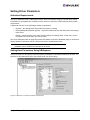
Setting Up Driver Parameters
To change driver parameter defaults, modify this section of the APInstall.cfg file. Locate the
[STORPORT.PARAMS] section in the APInstall.cfg file. This section follows Optional Configuration File
Changes. Under the[STORPORT.PARAMS] heading, list the parameters and new values for the driver to
use. All driver parameters need to be listed in a single line, separated by a semicolon. The
"EmulexOption=0x00000000" parameter must be included for the changes to be effective.
For example, Driver Parameter = “LinkTimeout = 45;NodeTimeout=60;EmulexOption=0x00000000;”
See the “Driver Parameter Reference Table” on page 80 for a listing of driver parameters and their
defaults and valid values.
Setting Up System Parameters
To change the system parameters, create a [SYSTEM.PARAMS] section in the APInstall.cfg file. Create
this section in the Optional Configuration File Changes heading in the [AUTOPILOT.CONFIG] section of
the APInstall.cfg file.
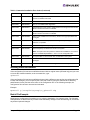
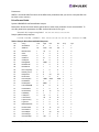
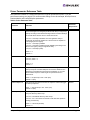
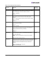
AutoPilot Installer Error Codes Reference Table
AutoPilot Installer sets an exit code to indicate whether an installation was successful or an error
occurred. These error codes allow AutoPilot Installer to be used in scripts with error handling. AutoPilot
Installer’s silent mode specifically returns the following values:
Table 2: Unattended Installation Error Codes
Error Code
Hex
Description
0
0x00000000
No errors.
2399141889
0x8F000001
No appropriate driver found.
2399141890
0x8F000002
The AutoPilot configuration file is not found.
2399141891
0x8F000003
Disabled HBAs detected in the system.
2399141892
0x8F000004
The selected driver is 64-bit and this system is 32-bit.
2399141893
0x8F000005
The selected driver is 32-bit and this system is 64-bit.
2399141894
0x8F000006
Other hardware installation activity is pending. AutoPilot Installer cannot run
until this is resolved.
Storport Miniport Driver User Manual
Page 18
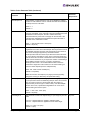
Table 2: Unattended Installation Error Codes (Continued)
Error Code
Hex
Description
2399141895
0x8F000007
(GUI Mode only) User cancelled execution because user did not wish to
perform a software-first install.
2399141896
0x8F000008
No drivers found.
2399141897
0x8F000009
One or more HBAs failed diagnostics.
2399141904
0x8F000010
(GUI Mode only) User chose to install drivers even though a recommended
QFE or Service Pack was not installed.
2399141920
0x8F000020
(GUI Mode only) User chose to stop installation because a recommended
QFE or Service Pack was not installed.
2399141899
0x8F00000B
Silent mode installation did not find any drivers of the type specified in the
config file.
2399141900
0x8F00000C
A silent reboot was attempted, but according to the operating system a
reboot is not possible.
2399141901
0x8F00000D
(GUI Mode only) A driver package download was cancelled.
2399141902
0x8F00000E
(Non-Enterprise) No HBAs were found in the system.
Note: To stop this error and perform a software first installation, be sure that
the line “enableEnterpriseMode = “True”” is in the configuration file.
2399141903
0x8F00000F
A required QFE or Service Pack was not detected on the system.
2399141836
0x8F000030
AutoPilot Installer was not invoked from an account with Administrator-level
privileges.
2399141952
0x8F000040
AutoPilot Installer has detected unsupported HBAs on the system.
Invoking AutoPilot Installer
If the configuration file has been modified and saved with its original name (APInstall.cfg) and you want
to invoke the AutoPilot Installer, at the command line, type:
apinstall
If the configuration file has been modified and saved with a different name and/or the configuration file
location has changed, you must specify the entire path location (using the standard drive:\directory
path\filename format) and the entire name of the configuration file. In the following example, the
configuration file has been renamed and relocated:
Example:
ApInstall g:\autopilot\mysetup\cs_apinstall.cfg
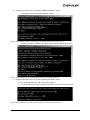
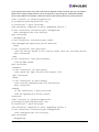
Batch File Example
Modifying the configuration file enables you to script the installation of a system's driver. The following
example batch file assumes that you have made mandatory changes to the APInstall.cfg file, as well as
any desired optional changes.
Storport Miniport Driver User Manual
Page 19
If your systems have been set up with a service that supports remote execution, then you can create a
batch file to remotely update drivers for all of the systems on the storage net. If Microsoft's RCMD
service was installed, for example, a batch file similar to the following would run remote execution:
rcmd \\server1 g:\autopilot\ApInstall
g:\autopilot\mysetup\apinstall.cfg
if errorlevel 1 goto server1ok
echo AutoPilot reported an error upgrading Server 1.
if not errorlevel 2147483650 goto unsupported
echo Configuration file missing.
goto server1ok
:unsupported
if not errorlevel 2147483649 goto older
echo Unsupported operating system detected.
:older
if not errorlevel 2001 goto none
echo The driver found is the same or older than the existing driver.
goto server1ok
:none
if not errorlevel 1248 goto noreport
echo No HBA found.
goto server1ok
:noreport
if not errorlevel 110 goto nocfg
echo Could not open installation report file.
goto server1ok
:nocfg
if not errorlevel 87 goto badcfg
echo Invalid configuration file parameters.
goto server1ok
:badcfg
if not errorlevel 2 goto server1ok
echo No appropriate driver found.
server1ok
rcmd \\server2 g:\autopilot\ApInstall
g:\autopilot\mysetup\apinstall.cfg
if errorlevel 1 goto server2ok
echo AutoPilot reported an error upgrading Server 2.
if not errorlevel 2147483650 goto unsupported
echo Configuration file missing.
goto server2ok
:unsupported
Storport Miniport Driver User Manual
Page 20
if not errorlevel 2147483649 goto older
echo Unsupported operating system detected.
:older2
if not errorlevel 2001 goto none2
echo The driver found is the same or older than the existing driver.
goto server2ok
:none2
if not errorlevel 1248 goto noreport2
echo No HBA found.
goto server2ok
:noreport
if not errorlevel 110 goto nocfg2
echo Could not open installation report file.
goto server2ok
:nocfg2
if not errorlevel 87 goto badcfg2
echo Invalid configuration file parameters.
goto server2ok
:badcfg2
if not errorlevel 2 goto server2ok
echo No appropriate driver found.
server2ok
Storport Miniport Driver User Manual
Page 21
Manually Installing or Updating the Storport Miniport Driver
Overview
You can install or update the Storport Miniport driver and utilities manually without using AutoPilot
Installer.
The Emulex PLUS (ElxPlus) driver supports the HBAnyware utility, persistent binding and LUN mapping
and masking. The ElxPlus driver replaces the adjunct driver. The ElxPlus driver must be installed before
you install the Storport Miniport driver.
If you currently use Storport Miniport 1.11a3 or earlier, the adjunct driver registry key must be removed
using the deladjct.reg file before you install the ElxPlus driver.The Storport Miniport driver, ElxPlus driver
and deladjct.reg file were extracted when you ran the Distribution Executable File.
Removing the Adjunct Driver Registry Key
If you are using Storport Miniport version 1.11a3 or earlier, you must remove the adjunct driver registry
key. See “Uninstalling the Emulex Drivers” on page 27.
Manually Installing the Emulex PLUS (ElxPlus) Driver for the First Time
Prerequisites
•
The Distribution Executable file has been downloaded from the Emulex Web site and extracted
to a directory on your local drive.
Note: Only one instance of the Emulex PLUS driver should be installed, even if you have
multiple HBAs or HBA ports installed in your system.
To install the ElxPlus driver from the desktop:
1. Select Start, Control Panel and Add Hardware. The Add Hardware Wizard window appears.
Click Next.
2. Select “Yes, I have already connected the hardware”. Click Next.
3. Select, “Add a new hardware device”. Click Next.
4. Select "Install the hardware that I manually select from a list (Advanced)". Click Next.
5. Select “Show All Devices”. Click Next.
6. Click Have Disk... Direct the Device Wizard to the location of elxplus.inf. If you have
downloaded the Storport Miniport files to the default directory, the path will be:
•
C:\Program Files\Emulex\AutoPilot Installer\Drivers\Storport\x86 for the 32-bit driver version
or
•
C:\Program Files\Emulex\AutoPilot Installer\Drivers\Storport\x64 for the x64-bit driver
version
or
•
C:\Program Files\Emulex\AutoPilot Installer\Drivers\Storport\IA64 for the Itanium 64-bit
driver version
7. Click OK.
8. Select "Emulex PLUS". Click Next and click Next again to install the driver.
Storport Miniport Driver User Manual
Page 22
9. Click Finish. The initial ElxPlus driver installation is complete. Continue with manual installation
of the Storport Miniport Driver. See page 23 for this procedure.
Manually Updating the Emulex PLUS (ElxPlus) Driver
Prerequisites
•
The Distribution Executable file has been downloaded from the Emulex Web site and extracted
to a directory on your local drive.
Note: Only one instance of the Emulex PLUS driver should be installed, even if you have
multiple HBAs or HBA ports installed in your system.
To update an existing ElxPlus driver from the desktop:
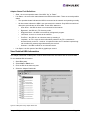
1. Select Start, Administrative Tools and Computer Management.
2. Click Device Manager (left pane).
3. Click the plus sign (+) next to the Emulex PLUS class (right pane) to show the ElxPlus driver
entry.
4. Right-click the ElxPlus driver entry and select Update Driver... from the menu.
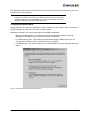
5. Select “No, not this time”. Click Next on the “Welcome to the Hardware Update Wizard” window.
Click Next.
6. Select "Install from a list or specific location (Advanced)". Click Next.
7. Select “Don’t Search. I will choose the driver to install”.
8. Click Have Disk... Direct the Device Wizard to the location of driver’s distribution kit. If you have
downloaded the Storport Miniport files to the default directory, the path will be:
•
C:\Program Files\Emulex\AutoPilot Installer\Drivers\Storport\x86 for the 32-bit driver version
or
•
C:\Program Files\Emulex\AutoPilot Installer\Drivers\Storport\x64 for the x64-bit driver
version
or
•
C:\Program Files\Emulex\AutoPilot Installer\Drivers\Storport\IA64 for the Itanium 64-bit
driver version
9. Click OK. Select "Emulex PLUS".
10. Click Next to install the driver.
11. Click Finish. The ElxPlus driver update is complete. Continue with manual installation of the
Storport Miniport Driver.
Manually Installing or Updating the Storport Miniport Driver
To update or install the Storport Miniport driver from the desktop:
1. Select Start, Control Panel and System.
2. Select the Hardware tab.
3. Click Device Manager.
4. Open the "SCSI and RAID Controllers" item.
Storport Miniport Driver User Manual
Page 23
5. Double-click the desired Emulex HBA.
Note: The driver will affect only the selected HBA. If there are other HBAs in the system,
you must repeat this process for each HBA. All DC models will be displayed in
Device Manager as two HBAs, therefore each HBA must be updated.
6. Select the Driver tab.
7. Click Update Driver. The Update Driver wizard starts.
8. Select “No, not this time”. Click Next on the “Welcome to the Hardware Update Wizard” window.
9. Select “Install from a list or specific location (Advanced)". Click Next.
10. Select "Don't search. I will choose the driver to install". Click Next.
11. Click Have Disk... Direct the Device Wizard to the location of oemsetup.inf. If you have
downloaded the Storport Miniport files to the default directory, the path will be:
•
C:\Program Files\Emulex\AutoPilot Installer\Drivers\Storport\x86 for the 32-bit driver version
or
•
C:\Program Files\Emulex\AutoPilot Installer\Drivers\Storport\x64 for the x64-bit driver
version
or
•
C:\Program Files\Emulex\AutoPilot Installer\Drivers\Storport\IA64 for the Itanium 64-bit
driver version
12. Click OK. Select "Emulex LightPulse LPX000, PCI Slot X, Storport Miniport Driver" (your HBA
model will be displayed here).
13. Click Next.
14. Click Finish.
The driver installation is complete. The driver should start up automatically. If the HBA is connected to a
FC switch, hub or data storage device, a blinking yellow light on the back of the HBA will indicate a link
up condition.
Manually Installing the Driver Utilities
Running this executable installs the HBAnyware and lputilnt utilities.
Prerequisites
•
The ElxPlus driver is installed.
•
The Storport Miniport driver is installed.
•
The Distribution Executable file has been downloaded from the Emulex Web site and extracted
to a directory on your local drive. If you have downloaded the Storport Miniport files to the default
directory, the path will be: C\\Program Files\Emulex\AutoPilot Installer\Utilities\.
To install the utility:
1. Run setupapps.exe.
2. Follow the instructions on the setup windows.
3. Click Finish in the last console window to exit Setup. The utility installation has completed.The
HBAnyware utility automatically starts running.
Storport Miniport Driver User Manual
Page 24
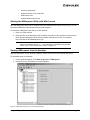
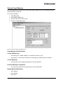
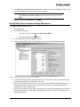
Uninstalling the Utility Package (the HBAnyware utility, Web Launch and
the lputilnt utility)
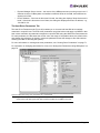
To uninstall the HBAnyware utility, the lputilnt utility and HBAnyware Web Launch (if it is installed):
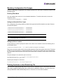
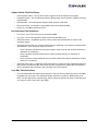
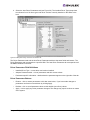
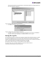
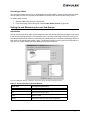
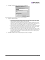
1. Click Start, Settings and Control Panel. The Add/Remove Programs window appears. Select
the Install/Uninstall tab. A window similar to Figure 11appears:
Figure 11: Add Remove Programs Window
2. Select the Emulex Fibre Channel item and click Change/Remove. A window similar to
Figure 12 appears:
Figure 12: Emulex HBAnyware Welcome Window
Storport Miniport Driver User Manual
Page 25
3. Click Next. The HBAnyware, lputilnt and Web Launch utilities are removed from the system.
Figure 13: Emulex HBAnyware Completion Window
4. Click Finish. Uninstallation is complete.
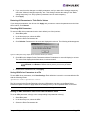
Uninstalling HBAnyware Web Launch
To uninstall HBAnyware Web Launch, but leave the HBAnyware utility installed:
1. Select Start, Programs, Emulex and HBAnyware WebLaunch Uninstall.
Figure 14: HBAnyware Web Launch Uninstallation Shortcut
Storport Miniport Driver User Manual
Page 26
The following dialog screen appears:
Figure 15: HBAnyware Web Launch, Uninstallation Dialog Screen
2. HBAnyware Web Launch is removed. Press any key to continue.
Uninstalling the Emulex Drivers
The Emulex Storport Miniport and PLUS (ElxPlus) drivers are uninstalled using the Device Manager.
Prerequisites
•
The Distribution Executable file has been downloaded from the Emulex Web site and extracted
to a directory on your local drive.
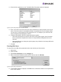
Procedures
To uninstall the Emulex Storport driver:
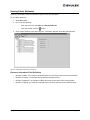
1. Select Start, All Programs, Administrative Tools and Computer Management.
2. Click Device Manager.
3. Double-click the HBA from which you want to remove the Storport Miniport driver. A devicespecific console window is displayed. Select the Driver tab.
4. Click Uninstall and click OK to uninstall.
To uninstall the ElxPlus driver (uninstall the ElxPlus driver only if all HBAs and installations of Emulex
miniport drivers are uninstalled).
After running Device Manager (steps 1 and 2 above):
1. Click the plus sign (+) next to the Emulex PLUS driver class.
2. Right-click the Emulex driver and click Uninstall.
3. Click OK in the Confirm Device Removal Window.
If you are uninstalling or updating an earlier version of the Storport Miniport driver (prior to version 1.20),
you need to remove the registry settings for the adjunct driver prior to manually installing a new Storport
Miniport driver.
To remove the adjunct driver registry settings:
1. Browse to the Storport Miniport driver version 1.20 (or later) driver kit that you downloaded and
extracted.
2. Double-click on the deladjct.reg file. A Registry Editor window appears to confirm that you want
to execute deladjct.reg.
3. Click Yes. The elxadjct key is removed from the registry.
Storport Miniport Driver User Manual
Page 27
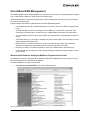
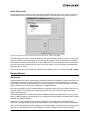
Configuration
Introduction
The Emulex®Storport Miniport driver has many options that you can modify to provide for different
behavior. You can change these options using the HBAnyware® utility or the LightPulse™® utility
(lputilnt).
The new HBAnyware Web Launch feature enables you to download and launch the HBAnyware user
interface by specifying the URL of a server that is hosting the HBAnyware Web Launch software. The
client machine from which the request is made does not need the HBAnyware package or an installed
Emulex HBA. You only need a standard web browser or some other application capable of making HTTP
requests. The Java runtime will be automatically downloaded if it is not already present.
•
Use the HBAnyware utility to do any of the following:
•
Discover local and remote hosts, host bus adapters (HBAs), targets and LUNs
•
Reset HBAs
•
Set up persistent binding
•
Set HBA driver parameters
•
Set driver parameters simultaneously to multiple HBAs using Batch Update
•
Set global driver parameters to HBAs
•
Update firmware on the single HBA or multiple HBAs using Batch Update
•
Enable boot code
•
Run diagnostic tests on HBAs
•
Manage out-of-band HBAs
•
Manage local and in-band remote HBAs
•
Launch the HBAnyware utility directly from your Web browser
•
Update EFIBoot (64-bit only)
Note: HBAnyware can only discover and manage remote HBAs on hosts running
HBAnyware’s elxhbamgr. For in-band management, remote capabilities of
HBAnyware are subject to fabric zoning configuration. Remote hosts you want to
discover and manage by HBAnyware must be in the same zone.
•
Use lputilnt to do any of following on local HBAs only:
•
Download Peripheral Component Interconnect (PCI) configuration data files
•
Assign an Arbitrated Loop Physical Address (AL_PA)
•
Perform global and target mapping and masking
•
Globally automap all logical unit numbers (LUNs)
•
Globally unmask all LUNs
•
Set up persistent binding
•
Hot swap a device
•
Set topology options
•
Map device identifiers (IDs)
•
Break SCSI reservations
Storport Miniport Driver User Manual
Page 28
•
Set driver parameters
•
Update firmware on the local HBA
•
Enable boot code
•
Update EFIBoot (64-bit only)
Starting the HBAnyware Utility with Web Launch
After the HBAnyware Web Launch software has been installed and the Web Launch server, you can
launch the HBAnyware utility directly with your Web browser.
To launch the HBAnyware utility with your Web browser:
1. Open your Web browser.
2. Enter the URL of an HBAnyware.jnlp file. Make sure that the URL specifies a remote server
which has the HBAnyware Web Launch software installed and running. For example:
http://138.239.20.30.5000/hbanyware.jnlp
Note: If the browser window displays “Emulex Corporation HBAnyware Demo of
HBAnyware WebStart web n.n.n.n ...” when attempting to start HBAnyware with Web
Launch, refer to the “Troubleshooting” section on page 149.
Starting HBAnyware from the Desktop
After the HBAnyware server has been installed, access the utility from the desktop Start menu.
To start HBAnyware for Windows:
1. On the Windows desktop, click Start, Programs and HBAnyware.
2. Initially discovery information for the host appears:
Figure 16: HBAnyware Utility, Discovery Information (Example)
Storport Miniport Driver User Manual
Page 29
The HBAnyware utility contains five basic elements: the menu bar, the toolbar, the discovery-tree, the
property tabs and the status bar.
Note: The element that you select in the discovery-tree determines whether a menu item or
toolbar icon is active. For example, if you select the local host or other system host,
the Reset Adapter item on the Adapter menu becomes unavailable. The Reset
Adapter toolbar button becomes unavailable as well.
Changing Management Mode
During installation you selected a management mode, however you can change it if the “Allow users to
change management mode from the utility" box was checked.
HBAnyware enables you to choose three types of host/HBA management:
•
Strictly Local Management - This setting only allows management of HBAs on this host.
Management of HBAs on this host from other hosts is not allowed.
•
Local Management Plus - This setting only allows management of HBAs on this host, but
management of HBAs on this host from another host is possible.
•
Full Management - This setting enables you to manage HBAs on this host and other hosts that
allow it.
Figure 17: HBAnyware Utility, Management Mode Window
Storport Miniport Driver User Manual
Page 30
Starting the HBAnyware Security Configurator
Note: Before you start the Security Configurator, you must make sure that all of the systems
that are part of, or will be part of, the security configuration are online on the FC network
so that they receive updates or changes made to the security configuration.
Any system already part of the security installation might not run with the proper security
attributes if updates to the security configuration are made while it is offline. Any system
that is part of the security installation and that is offline when the Security Configurator
starts will not be available for security configuration changes even if it is brought online
while the Security Configurator is running.
To start the HBAnyware Security Configurator for Windows Server 2003 or Windows 2000 Server:
1. On the desktop, click Start, Programs and HBAnyware Security Configurator. The
HBAnyware Security Configurator Discovery window appears:
Figure 18: HBAnyware Security Configurator Discovery Window
2. After discovery is completed, the HBAnyware Security Configurator appears.
Figure 19: HBAnyware Security Configurator, Access Control Group Tab
Storport Miniport Driver User Manual
Page 31
Starting HBAnyware from the Command Line
You can launch HBAnyware from the command line. For more information on the command-line
interface, see “Using the HBAnyware Command-Line Interface” on page 35.
To launch HBAnyware from the command line:
1. Type "HBAnyware" and press <ENTER>. This starts HBAnyware in in-band access. You can
also start the utility in out-of-band access by adding an argument in the form "h=<host>". The
<host> argument may be either the internet protocol (IP) address of the host or its system name.
The call will use a default IP port of 23333, but you can override this by optionally appending a
colon (:) and the IP port.
Note: Remember that not all HBAs for a specific host can run in-band. Therefore, if you run
out-of-band, that host may display HBAs that do not appear when running in-band.
Note: HBAnyware can only discover and manage remote HBAs on hosts running
HBAnyware's elxhbamgr. For in-band management, remote capabilities of
HBAnyware are subject to fabric zoning configuration. Remote hosts you want to
discover and manage by HBAnyware must be in the same zone.
Examples of Modifications
HBAnyware h=138.239.82.2
HBAnyware will show HBAs in the host with the IP address 138.239.82.2.
HBAnyware h=Util01
HBAnyware will show HBAs in the host named Util01.
HBAnyware h=138.239.82.2:4295
HBAnyware will show HBAs in the host with the IP address 138.239.82.2 using IP Port 4295.
HBAnyware h=Util01:4295
HBAnyware will show HBAs in the host named Util01 using IP port 4295.
Run this modified command line to launch HBAnyware for a single, remote host in local mode.
Storport Miniport Driver User Manual
Page 32
HBAnyware Window Element Definitions
Figure 20: HBAnyware Utility Window with Element Call Outs
The Menu Bar
The menu bar contains command menus that enable you to perform a variety of tasks such as exiting
HBAnyware, resetting HBAs and sorting items in the discovery-tree. Many of the menu bar commands
are also available from the toolbar.
The Toolbar
The toolbar contains buttons that enable you to refresh the discovery-tree, reset the selected HBA and
sort the discovery-tree. The toolbar is visible by default. Many of the toolbar functions are also available
from the menu bar.
Use the Toolbar item in the View menu to hide/view the toolbar. If the menu item is checked, the toolbar
is visible.
The Toolbar Buttons
Click Rediscover to refresh the discovery-tree display.
Click Reset to reset the selected HBA.
Storport Miniport Driver User Manual
Page 33
Sort Toolbar Buttons
Sort discovered HBAs by host name, fabric addresses or local HBAs. By default, HBAs are
sorted by host name, with local HBAs appearing first.
Show only local or remote HBAs. See page 57 for details on sorting icons.
Sort by host name (default)
Sort by fabric address
Local HBAs only
Help
Discovery-Tree
The discovery-tree (left pane) shows icons that represent discovered network storage area network
(SAN) elements (local host name, system host names and all HBAs active on each host). Targets and
LUNs, when present, are also displayed.
Figure 21: HBAnyware Utility, Discovery-Tree
Discovery-Tree Icons
Discovery-tree icons represent the following:
The local host.
Other hosts connected to the system.
A green HBA icon with black descriptive text represents an online HBA.
Storport Miniport Driver User Manual
Page 34
A gray HBA icon with red descriptive text represents an HBA that is offline or otherwise temporarily inaccessible. Several situations could cause an offline or inaccessible HBA:
•
The HBA on a local host is not connected to the network but is still available for local access.
•
The HBA on a local host has malfunctioned and is inaccessible to the local host as well as
the network.
•
The HBA on a local host is busy performing a local download and therefore temporarily
inaccessible to the local host as well as the network.
The Target icon represents connections to individual storage devices.
The LUN icon represents connections to individual LUNs.
Property Tabs
The property tabs display configuration, statistical and status information for network elements. The set
of available tabs is context-sensitive, depending on the type of network element or HBA currently
selected in the discovery-tree.
Status Bar
As you navigate through the menu bar or the toolbar, help messages appear on the status bar near the
bottom of the HBAnyware window.
The status bar is visible by default. Use the Status Bar item in the View menu to hide the status bar. If
checked, the status bar is visible.
Using the HBAnyware Command-Line Interface
The CLI (command-line interface) Client component of HBAnyware provides access to the capabilities of
the Remote Management library from a console command prompt. Use this component in scripted
operations from within shell scripts, batch files, or the specific platform equivalent.
Note: HBAnyware can only discover and manage remote HBAs on hosts running
HBAnyware's elxhbamgr.
For in-band management, remote capabilities of HBAnyware are subject to fabric
zoning configuration. Remote hosts you want to discover and manage by HBAnyware
must be in the same zone.
HbaCmd can be run in out-of-band mode if you make the first argument 'h=<host>'. For example:
c:\>hbacmd h=cp-hp5670 listhbas
c:\>hbacmd h=138.239.91.121 listhbas
The CLI Client
The CLI Client is a console application named HBACMD.EXE. Each time you run this application from
the command line, a single operation is performed.
The first parameter of this command is the requested operation. When the specified operation
completes, the command prompt is displayed. Most operations retrieve information about an entity on
the SAN and show that information on the console.
Storport Miniport Driver User Manual
Page 35
Most of the CLI Client commands require one or more additional parameters that specify the nature of
the command. A parameter used by many HBACMD commands specifies the World Wide Port Name
(WWPN) of the HBA target of the command. For example, the following command displays the port
attributes for the HBA with the specified WWPN:
c:\>hbacmd portattrib 10:00:00:00:c9:20:20:20
Syntax Rules
The syntax rules for HBACMD are as follows:
•
All CLI Client commands and their arguments are case insensitive.
•
The requested operation must contain at least three characters, or as many as needed to
distinguish it from any other operation.
•
Whenever a WWPN is specified, individual fields are separated by colons (:) or spaces ( ). When
using space separators, the entire WWPN must be enclosed in quotes (").
Out-of-Band Access
Out-of-band (OOB) access enables you to access HBAs by their IP-address or by the name of the host
on which they reside. Since HBAs may exist on a host but not be a part of a FC network, they will not
appear during normal in-band discovery. Thus, OOB access enlarges the number of HBAs that you can
query or modify.
Note: A local host cannot be accessed out-of-band.
OOB access via HBACMD uses an additional parameter on the command line. The parameter must be
the first parameter in the list, coming immediately after HBACMD. The remaining parameters are those
documented for each operation.
Note: You can also access an in-band HBA by its OOB address.
The format of the OOB parameter is:
h={<IPAddress> | <host-name>}
Some examples are:
h=128.239.91.88
h=cp-compaq8000
The following lists all HBAs running on the host with a specified IP address:
hbacmd h=128.239.91.88 listHBAs
If you don’t know the IP address, but you know the host name, enter:
hbacmd h=cp-compaq8000 listHBAs
If the host is unreachable, the command will return an error.
Storport Miniport Driver User Manual
Page 36
The CLI Client Command Reference
Version
Syntax: HBACMD Version
Description: Shows the current version of the HBAnyware CLI Client application. To view the current
version, type:
hbacmd version
Sample response:
HBAnyware Command Line Interface: Version 3.0
Parameters: None.
ListHBAs
Syntax: HBACMD ListHBAs
Description: Shows a list of the discovered manageable Emulex HBAs and some of their attributes. The
list will contain one 6-attribute group for each discovered HBA. Example of an attribute group list:
Manageable HBA List
Port WWN:
10:00:00:00:c9:20:08:cc
Node WWN:
20:00:00:00:c9:20:08:cc
Fabric Name:10:00:00:60:69:90:0b:f6
Flags:
0000f900Host Name: CP-EMULEX-DECPC
Mfg:
Emulex Corporation
Parameters: None.
SaveConfig
Syntax: HBACMD SaveConfig <wwpn> <filename> <ctrlword>
Description: Saves the contents of the driver parameter list to a file for the specified HBA. The ASCII file
lists parameter definitions delimited by a comma. Each definition is of the form:
<parameter-name>=<parameter-value>
Save either the values of the global set or those specific to the referenced HBA. The file created by this
command stores itself in the Emulex Repository directory.
Example:
hbacmd SaveConfig elxstor-5-1.20A0.dpv 10:00:00:00:c9:2e:51:2e N
Sample response:
HBACMD_SaveConfig: Success writing driver parameters to file
C:\Program Files\HBAnyware\Emulex Repository\elxstor-5-1.20A.dpv
Parameters:
WWPN - the World Wide Port Name of the HBA (this HBA can be either local or remote).
filename - the file name that will contain the driver parameter list upon successful completion of this
command.
ctrlword - G = save the global parameter set, N = save the local (HBA-specific) parameter set.
Storport Miniport Driver User Manual
Page 37
HBAAttrib
Syntax: HBACMD HBAAttrib <wwpn>
Description: Shows a list of all HBA attributes for the HBA with the specified WWPN. To view the
attributes for the HBA, type:
hbacmd hbaattrib 10:00:00:00:c9:20:08:cc
Sample response:
HBA Attributes for 10:00:00:00:c9:20:08:cc
Host Name
: CP-EMULEX-DECPC
Manufacturer
: Emulex Corporation
Serial Number : 0000c92008cc
Model
: LP9000
Model Desc
: Emulex LightPulse LP9000 1 Gigabit PCI Fibre
Channel Adapter
Node WWN
: 20 00 00 00 c9 20 08 cc
Node Symname
: Emulex LP9000 FV3.92A2 DV5-5.20A0
HW Version
: 1002806D
Opt ROM Version:
FW Version
: 3.92A2
Vender Spec ID : 10DF
Number of Ports: 1
Driver Name
: lpxnds
Device ID
: F900
HBA Type
: LP9000
Operational FW : SLI-2 Overlay
SLI1 FW
: LP9K SLI-1 Overlay 3.92a2
SLI2 FW
: LP9K SLI-2 Overlay 3.92a2
IEEE Address
: 00 00 c9 20 08 cc
Boot BIOS
: Disabled
Driver Version : 5-5.20A0; HBAAPI v2.2.a, 10-19-04
Kernel Version : 1.30a5
Parameters:
WWPN - the World Wide Port Name of the HBA (this HBA can be either local or remote).
PortAttrib
Syntax: HBACMD PortAttrib <wwpn>
Description: Shows a list of all port attributes for the port with the specified WWPN. To view the port
attributes for the HBA, type:
hbacmd portattrib 10:00:00:00:c9:20:08:cc
Sample response:
Port
Node
Port
Port
Port
Port
Port
Port
Port
Attributes for
WWN
WWN
Symname
FCID
Type
State
Service Type
Supported FC4
10:00:00:00:c9:20:08:cc
: 20 00 00 00 c9 20 08 cc
: 10 00 00 00 c9 20 08 cc
:
: 6A0200
: Fabric
: Operational
: 4
: 00 00 01 00 00 00 00 01
00 00 00 00 00 00 00 00
00 00 00 00 00 00 00 00
Storport Miniport Driver User Manual
Page 38
Port Active FC4
Port Supported
Port Speed
Max Frame Size
OS Device Name
Num Discovered
Fabric Name
00 00 00 00 00 00 00 00
: 00 00 01 00 00 00 00 01
00 00 00 00 00 00 00 00
00 00 00 00 00 00 00 00
00 00 00 00 00 00 00 00
Speed: 1 GBit/sec.
: 1 GBit/sec.
: 2048
: \\.\Scsi2:
Ports: 18
: 10 00 00 60 69 30 1e 4f
Parameters:
WWPN - the World Wide Port Name of the HBA (this HBA can be either local or remote).
PortStat
Syntax: HBACMD PortStat <wwpn>
Description: Shows all port statistics for the HBA with the specified WWPN. To view port statistics for
the HBA, type:
hbacmd portstat 10:00:00:00:c9:20:08:cc
Sample response:
Port Statistics for 10:00:00:00:c9:20:08:cc
Exchange Count
:
Responder Exchange Count:
TX Seq Count
:
RX Seq Count
:
TX Frame Count
:
RX Frame Count
:
TX Word Count
:
RX Word Count
:
TX KB Count
:
RX KB Count
:
LIP Count
:
NOS Count
:
Error Frame Count
:
Dumped Frame Count
:
Link Failure Count
:
Loss of Sync Count
:
Loss of Signal Count
:
Prim Seq Prot Err Count :
Invalid TX Word Count
:
nvalid RX Frame CRC Cnt :
Link Transition Count
:
Active RPI Count
:
Active XRI Count
:
Rx Port Busy Count
:
Rx Fabric Busy Count
:
Primary Sequence Timeout:
Elastic Buffer Overrun :
Arbitration Timout
:
1496534
37505
1588007
1561255
1588695
1561892
19821312
66368000
77427
259250
1
n/a
0
n/a
0
9
0
0
0
0
0
0
0
0
0
0
0
0
Parameters:
WWPN - the World Wide Port Name of the HBA (this HBA can be either local or remote).
Storport Miniport Driver User Manual
Page 39
ServerAttrib
Syntax: HBACMD ServerAttrib <WWPN>
Description: Shows a list of attributes of the server running locally to the specified HBA. To view the
server attributes for the HBA, type:
hbacmd serverattrib 10:00:00:00:c9:20:08:cc
Sample response:
Server Attributes for 10:00:00:00:c9:20:08:cc
Host Name
: CP-EMULEX-DECPC
FW Resource Path: C:\Program Files\HBAnyware\Emulex Repository
DR Resource Path: C:\Program Files\HBAnyware\Emulex Repository
HBAnyware Server Version: 3.0
Parameters:
WWPN - the World Wide Port Name of any HBA local to the designated server (the HBA itself can be
either local or remote).
TargetMapping
Syntax: HBACMD TargetMapping <wpm>
Description: Shows a list of mapped targets and the LUNs attached to each for the port with the
specified WWPN. To view the target mapping for 10:00:00:00:c9:20:08:0c, type:
hbacmd targetmapping 10:00:00:00:c9:20:08:cc
Sample response:
Target Mapping for 10:00:00:00:c9:20:08:cc
FCP ID: 10FEF
SCSI Bus Number: 1
SCSI Target Num: 0
Node WWN: 50:06:04:8A:CC:C8:99:00
Port WWN: 50:06:04:8A:CC:C8:99:00
OS Device Name : \\.\Scsi2:1:0:0
FCP LUN 00: 0000 0000 0000 0000
SCSI OS Lun: 0
Vendor ID: EMC
Product ID: SYMMETRIX
Product Version: 5669
SCSI Capacity: 4315 MB
Block Size: 512 Bytes
FCP ID: 10101
SCSI Bus Number: 1
SCSI Target Num: 1
Node WWN: 20:00:00:D0:B2:00:30:40
Port WWN: 20:00:00:D0:B2:00:30:40
OS Device Name: \\.\Scsi2:1:1:0
FCP LUN 00
0000 0000 0000 0000
SCSI OS Lun: 0
Vendor ID: XIOTECH
Product ID: STORAGE
Storport Miniport Driver User Manual
Page 40
Product Version:
1.00
SCSI Capacity: 2009 MB
Block Size: 512 Bytes
FCP LUN 01: 0001 0000 0000 0000
SCSI OS Lun: 1
Vendor ID:
XIOTECH
Product ID: STORAGE
Product Version: 1.00
SCSI Capacity: 2009 MB
Block Size: 512 Bytes
Parameters:
WWPN - the World Wide Port Name of the HBA (this HBA can be either local or remote).
Reset
Syntax: HBACMD Reset <wwpn>
Description: Resets the HBA with the specified WWPN. An HBA reset may require several seconds to
complete, especially for remote devices. This command will return for additional input only after the reset
has finished. To reset an HBA whose WWPN is 10:00:00:00:c9:e:51:2e, type:
hbacmd reset 10:00:00:00:c9:2e:51:2e
Sample response:
Reset HBA 10:00:00:00:c9:2e:51:2e
Parameters:
WWPN - the World Wide Port Name of the HBA (this HBA can be either local or remote).
Download
Syntax: HBACMD Download <wwpn> <filename>
Description: Loads the specified firmware image to the HBA with the specified WWPN. To load the
firmware image located in hdc190a4.dwc to an HBA with WWPN 10:00:00:00:c9:2e:51:2e, type:
hbacmd download 10:00:00:00:c9:2e:51:2e hdc190a4.dwc
Sample response for a successful download:
Downloading hdc190a4.dwc to hba 10:00:00:00:c9:2e:51:2e
Download Complete.
Parameters:
WWPN - the World Wide Port Name of the HBA that is the target of the firmware download (this HBA
can be either local or remote).
FileName - the file name of the firmware image you want to load (this can be any file accessible to the
CLI client application).
Storport Miniport Driver User Manual
Page 41
PersistentBinding
Syntax: HBACMD PersistentBinding <wwpn> <source>
Description: Queries the presence of any persistent binding for the specified WWPN. The <source>
queries either the configured or live state of any present binding. To view the configured persistent
binding for an HBA whose WWPN is 10:00:00:00:c9:20:0d:36, type:
hbacmd persistentbinding 10:00:00:00:c9:20:0d:36 C
Sample response:
Persistent Binding for 10:00:00:00:c9:20:0d:36
Bind Type
:
FCP ID
:
SCSI Bus Number:
SCSI Target Num:
Node WWN
:
Port WWN
:
OS Device Name :
WWPN
10101
0
0
20:00:00:D0:B2:00:30:40
20:00:00:D0:B2:00:30:40
\\.\Scsi:4:0
Bind Type
: WWPN
FCP ID
: 10FEF
SCSI Bus Number: 0
SCSI Target Num: 1
Node WWN
: 50:06:04:8A:CC:C8:99:00
Port WWN
: 50:06:04:8A:CC:C8:99:00OS
Device Name : \\.\Scsi:4:1If no such binding exists, only the
first line is returned.
Parameters:
WWPN - the World Wide Port Name of the HBA persistent bindings that you want to query (this HBA can
be either local or remote).
Source - C if the configured state is being queried, L if the live state is being queried.
AllNodeInfo
Syntax: HBACMD AllNodeInfo <wwpn>
Description: Shows target node information for each target accessible from the specified HBA. To view
the target node data for 10:00:00:00:c9:20:0d:36, type:
Hbacmd allnodeinfo 10:00:00:00:c9:20:0d:36
Sample response:
All Node Info for 10:00:00:00:c9:20:0d:36
Node Type
:
FCP ID
:
SCSI Bus Number:
SCSI Target Num:
Node WWN
:
Port WWN
:
OS Device Name :
UNKNOWN
10101
0
0
20:00:00:D0:B2:00:30:40
20:00:00:D0:B2:00:30:40
\\.\Scsi4:0:0
Node Type
: UNKNOWN
FCP ID
: 10FEF
SCSI Bus Number: 0
Storport Miniport Driver User Manual
Page 42
SCSI Target Num:
Node WWN
:
Port WWN
:
OS Device Name :
1
50:06:04:8A:CC:C8:99:00
50:06:04:8A:CC:C8:99:00
\\.\Scsi4:0:1
Parameters:
WWPN - the World Wide Port Name of the HBA target node information that you want to query (this HBA
can be either local or remote).
SetPersistentBinding
Syntax: HBACMD SetPersistentBinding <wwpn> <scope> <bindtype> <ID> \
<scsibus> <scsitarget>
Description: Sets a persistent binding between a FC target and a SCSI bus and target. The binding can
be to a target WWPN, target WWNN, or target D_ID.
To bind permanently, on behalf of HBA 10:00:00:00:c9:2e:51:2e, target WWPN 20:00:00:d0:b2:00:30:40
to SCSI bus 1, target 3, type:
hbacmd setpersistentbinding 10:00:00:00:c9:2e:51:2e P P \
20:00:00:d0:b2:00:30:40 1 3
To bind immediately, on behalf of HBA 10:00:00:00:c9:2e:51:2e, target D_ID 10101 to SCSI bus 1, target
3, type:
hbacmd setpersistentbinding 10:00:00:00:c9:2e:51:2e I D \
10101 1 3
If there are no errors, a response to the last example would be:
Set Persistent Binding for 10:00:00:00:c9:2e:51:2e I D \
10101 1 3
Parameters:
WWPN - the World Wide Port Name for which a persistent binding will be set (the HBA can be either
local or remote).
scope - P = binding is permanent (survives across reboot), I = binding is immediate, B = binding is both
permanent and immediate.
bindtype - P = enable binding by WWPN, N = enable binding by WWNN, D = enable binding by D_ID.
ID - Target WWPN if bindtype = P, Target WWNN if bindtype = N, Target D_ID if bindtype = D.
scsibus - the bus number of SCSI device.
scsitarget - the target number of SCSI device.
Storport Miniport Driver User Manual
Page 43
RemoveAllPersistentBinding
Syntax: HBACMD RemoveAllPersistentBinding <wwpn>
Description: Removes all persisting bindings associated with the referenced HBA. To remove all
persistent bindings for 10:00:00:00:c9:21:5e:21, type:
hbacmd removeallpersistentbinding 10:00:00:00:c9:21:5e:21
Sample response:
Remove All Persistent Binding for 10:00:00:00:c9:2e:51:2e
Parameters:
WWPN - the World Wide Port Name of the HBA for which you want to remove all persistent bindings.
(this HBA can be either local or remote).
RemovePersistentBinding
Syntax: HBACMD RemovePersistentBinding <wwpn> <bindtype> <ID> \
<scsibus> <scsitarget>
Description: Removes a persistent binding between a FC target and a SCSI bus and target. The binding
to be removed can be to a target WWPN, target WWNN, or target D_ID.
To remove, on behalf of HBA 10:00:00:00:c9:2e:51:2e, the binding between target
WWPN=20:00:00:d0:b2:00:30:40 and SCSI bus 1, target 3, type:
hbacmd removepersistentbinding 10:00:00:00:c9:2e:51:2e P \
20:00:00:d0:b2:00:30:40 1
To remove, on behalf of HBA 10:00:00:00:c9:2e:51:2e, the binding between target D_ID=10101 and
SCSI bus 1, target 3, type:
hbacmd removepersistentbinding 10:00:00:00:c9:2e:51:2e D \
10101 1 3
If no errors occur, a response to the last example would be:
Remove Persistent Binding for 10:00:00:00:c9:2e:51:2e D \
10101 1 3
Parameters:
WWPN - the World Wide Port Name of the HBA for which you want to remove a persistent binding (the
HBA can be either local or remote).
bindtype - P = enable binding by WWPN, N = enable binding by WWNN, D = enable binding by D_ID.
ID - Target WWPN if bindtype = P, Target WWNN if bindtype = N, Target D_ID if bindtype = D.
scsibus - the bus number of SCSI device.
scsitarget - the target number of SCSI device.
BindingCapabilities
Syntax: HBACMD BindingCapabilities <wwpn>
Description: Shows the binding capabilities present at the referenced HBA. To view the binding
capabilities at 10:00:00:00:c9:21:5e:21, type:
hbacmd bindingcapabilities 10:00:00:00:c9:21:5e:21
Storport Miniport Driver User Manual
Page 44
Sample response:
Binding Capability for 10:00:00:00:c9:2e:51:2e
Can bind to D_ID
Can bind to WWPN
Can bind to WWNN
Can bind AUTOMAP
Can bind CONFIGURED
Parameters:
WWPN - the World Wide Port Name of the HBA binding capabilities that you want to query (this HBA
can be either local or remote).
BindingSupport
Syntax: HBACMD BindingSupport <wwpn> <source>
Description: Shows the binding support available at the referenced HBA. To view the configured binding
support for 10:00:00:00:c9:21:5e:21, type:
hbacmd bindingsupport 10:00:00:00:c9:21:5e:21 C
Sample response:
Binding Support for 10:00:00:00:c9:2e:51:2e
Can bind to WWPN
Can bind AUTOMAP
Parameters:
WWPN - the World Wide Port Name of the HBA binding support that you want to query (this HBA can be
either local or remote).
source - C if the support is being queried, L if the live support is being queried.
SetBindingSupport
Syntax: HBACMD SetBindingSupport <wwpn> <bindflag>
Description: Sets the binding support(s) for the referenced HBA. To enable binding support for WWPN
and Automap on HBA 10:00:00:00:c9:21:5e:21, type:
hbacmd setbindingsupport 10:00:00:00:c9:21:5e:21 P1
Sample response:
Set Binding Support for 10:00:00:00:c9:21:5e:21 P1
Parameters:
WWPN - the World Wide Port Name of the HBA binding that you want to set (this HBA can be either
local or remote).
bindflag - 1 = enable support for Automap binding, 0 = disable support for Automap binding, P1 = enable
support for WWPN binding and Automap, N1 = enable support for WWNN binding and Automap, D1 =
enable support for D_ID binding and Automap, P0 = enable support for P, disable Automap, N0 = enable
support for N, disable Automap D0 = enable support for D, disable Automap.
Storport Miniport Driver User Manual
Page 45
DriverParams
Syntax: HBACMD DriverParams <wwpn>
Description: Shows the name and values of each driver parameter for the selected HBA. To view the
driver parameters for HBA 10:00:00:00:c9:2e:51:2e, type:
hbacmd driverparams 10:00:00:00:c9:2e:51:2e
Sample (abbreviated) response:
Driver Params for 10:00:00:00:c9:2e:51:2e
Table 3: Sample DriverParams Response
IDX
string
Low
High
Def
Cur
Exp
Dyn
00
AbortStatus
0
ff
e
e
1
1
01
ARBTOV
1f4
4e20
5dc
5dc
1
5
02
BlinkTimeOut
1
1E
8
8
1
0
03
Class
1
2
2
2
1
1
04
CrfIntrpt
0
1
0
0
1
5
05
CrfMsCnt
0
3f
0
0
1
5
06
CrfRspCnt
0
ff
0
0
1
5
07
DebugMask
0
efffffff
0
0
0
5
08
DisableAck0
0
1
0
0
1
5
09
DiscMethod
0
1
1
0
1
1
0a
DiscoveryDelay
0
7
0
0
1
1
0b
ElsRetryCount
1
ff
1
1
1
1
0c
ElsRjtCount
0
ff
2d
2d
1
1
0d
ElsTimeOut
0
1
0
0
1
1
0e
EmulexOption
0
7fffffff
d200
da00
1
0
0f
EnableDPC
0
1
0
1
1
1
10
ErrRetryMax
0
fffffffe
1
1
1
1
11
FrameSizeMSB
0
8
0
0
1
5
12
HardAddress
0
1
0
0
1
0
13
HlinkTimeOut
0
ff
1e
1e
1
1
14
InitialDelay
0
1
1
1
1
0
15
LinkSpeed
0
10
0
0
1
1
16
LinkTimeOut
1f4
3c
3c
1
1
17
LipFFrecovery
0
1
0
0
1
1
18
LogErrors
0
1
0
0
1
1
19
MapNodeName
0
1
0
0
1
0
1a
NodeTimeOut
0
ff
14
14
1
1
1b
QueueAction
0
2
0
0
1
1
1c
QueueDepth
1
ff
20
20
1
1
1d
QueueTarget
0
1
0
0
1
5
1e
QueueIncStep
0
100
2
2
1
1
1f
RegFcpType
0
1
1
1
1
1
20
ResetFF
0
1
0
0
1
1
21
ResetTPRLO
0
2
0
0
1
1
22
RetryNodePurge
0
1
1
1
1
1
23
RTTOV
a
ff
64
64
1
5
Storport Miniport Driver User Manual
Page 46
Parameters:
WWPN - the World Wide Port Name of the HBA driver parameters that you want to view (this HBA can
be either local or remote).
DriverParamsGlobal
Syntax: HBACMD DriverParamsGlobal <wwpn>
Description: Shows the name and the global value of each driver parameter for the selected HBA. To
view the global driver parameters for HBA 10:00:00:00:c9:2e:51:2e, type:
hbacmd driverparamsglobal 10:00:00:00:c9:2e:51:2e
Sample (abbreviated) response:
Driver Params (Global) for 10:00:00:00:c9:2e:51:2e. Values in HEX.
Table 4: Sample DriverParamsGlobal Response
DX
string
Low
High
Def
Cur
Exp
Dyn
00
AbortStatus
0
ff
e
e
1
1
01
ARBTOV
1f4
4e20
5dc
5dc
1
5
02
BlinkTimeOut
1
1E
8
8
1
0
03
Class
1
2
2
2
1
1
04
CrfIntrpt
0
1
0
0
1
5
05
CrfMsCnt
0
3f
0
0
1
5
06
CrfRspCnt
0
ff
0
0
1
5
07
DebugMask
0
efffffff
0
0
0
5
08
DisableAck0
0
1
0
0
1
5
09
DiscMethod
0
1
1
0
1
1
0a
DiscoveryDelay
0
7
0
0
1
1
0b
ElsRetryCount
1
ff
1
1
1
1
0c
ElsRjtCount
0
ff
2d
2d
1
1
0d
ElsTimeOut
0
1
0
0
1
1
0e
EmulexOption
0
7fffffff
d200
da00
1
0
0f
EnableDPC
0
1
0
1
1
1
10
ErrRetryMax
0
fffffffe
1
1
1
1
11
FrameSizeMSB
0
8
0
0
1
5
12
HardAddress
0
1
0
0
1
0
13
HlinkTimeOut
0
ff
1e
1e
1
1
14
InitialDelay
0
1
1
1
1
0
15
LinkSpeed
0
10
0
0
1
1
16
LinkTimeOut
1f4
3c
3c
1
1
17
LipFFrecovery
0
1
0
0
1
1
18
LogErrors
0
1
0
0
1
1
19
MapNodeName
0
1
0
0
1
0
1a
NodeTimeOut
0
ff
14
14
1
1
1b
QueueAction
0
2
0
0
1
1
1c
QueueDepth
1
ff
20
20
1
1
1d
QueueTarget
0
1
0
0
1
5
1e
QueueIncStep
0
100
2
2
1
1
Storport Miniport Driver User Manual
Page 47
Table 4: Sample DriverParamsGlobal Response (Continued)
1f
RegFcpType
0
1
1
1
1
1
20
ResetFF
0
1
0
0
1
1
21
ResetTPRLO
0
2
0
0
1
1
22
RetryNodePurge
0
1
1
1
1
1
23
RTTOV
a
ff
64
64
1
5
Parameters: the World Wide Port Name of the HBA driver parameters that you want to view (this HBA
can be either local or remote).
SetDriverParam
Syntax: HBACMD SetDriverParam <wwpn> <ctrlword> <param> <value>
Description: Changes the value of the specified driver parameter operating the referenced HBA, and
designates the scope of that change. To change the value of the LinkSpeed parameter (for example) for
10:00:00:00:c9:2e:51:2e and make it permanent, type:
hbacmd SetDriverParam 10:00:00:00:c9:2e:51:2e p linkspeed 2
Sample response:
Set Driver Parameter linkspeed=2(p) for 10:00:00:00:c9:2e:51:2e
Parameters:
WWPN - the World Wide Port Name of the HBA parameter that you want to modify (this HBA can be
either local or remote).
ctrlword - P = make change permanent, G = make change global, B = make change both permanent and
global, N = make change neither permanent nor global.
param - the name of the parameter whose value you want to modify.
Value - the new value you want to assign to the parameter.
SetBootBios
Syntax: HBACMD SetBootBios <wwpn> <ctrlword>
Description: Enables or disables the Boot BIOS on the referenced HBA. To enable the Boot BIOS for
10:00:00:00:c9:2e:51:2e, type:
hbacmd setbootbios 10:00:00:00:c9:2e:51:2e E
Parameters:
WWPN -the World Wide Port Name of the HBA Boot BIOS that you want to enable or disable (this HBA
can be either local or remote).
altword - E = enable the Boot BIOS, D = disable the Boot BIOS.
Storport Miniport Driver User Manual
Page 48
PciData
Syntax: HBACMD PciData <wwpn>
Description: Shows PCI configuration data for the HBA specified by the WWPN. To show PCI
configuration data for HBA 10:00:00:00:c9:2e:51:2e, type:
hbacmd pcidata 10:00:00:00:c9:2e:51:2e
Sample response:
Table 5: Sample PciData Response
Vendor ID:
ox10DF
Device ID:
0xF900
Command:
0x011F
Status:
0x02a0
Revision ID
0x01
Prog If:
0x00
Subclass:
0x04
BaseClass:
0x0C
Cache Line Size:
0x10
Latency Timer:
0x40
Header Type:
0x00
Built In Self Test:
0x00
Base Address 0:
0xFE2fc004
Base Address 1:
0x00000000
Base Address 2:
0xFE2FD804
Base Address 3:
0x00000000
Base Address 4:
0x0000E401
Base Address 5:
0x00000000
CIS:
0x00000000
Sub Vendor ID:
0x10DF
SubSystem ID:
0xF900
ROM Base Address:
0xFE300000
Interrupt Line:
0x12
Interrupt Pin:
0x01
Minimum Grant:
0xFF
Maximum Latency:
0x00
Parameters:
WWPN - the World Wide Port Name of the HBA PCI configuration data that you want to show.
Wakeup
Syntax: HBACMD wakeup <wwpn>
Description: Shows wakeup parameter data for the HBA specified by the WWPN. To show wakeup
parameter data for HBA 10:00:00:00:c9:2e:51:2e, type:
hbacmd wakeup 10:00:00:00:c9:2e:51:2e
Sample response:
Wakeup Parameters:
Initial Load:
0x02C03992
Flags:
0x00000000
0x00103411
Boot BIOS
0x03433290
0x00101303
SLI-1:
0x06433992
0x00103411
SLI-2:
0x07433992
0x00103411
Has Expansion ROM
0
Parameters:
WWPN - the World Wide Port Name of the HBA wakeup parameter data that you want to show.
Storport Miniport Driver User Manual
Page 49
LoopMap
Syntax: HBACMD loopmap <wwpn>
Description: Shows the arbitrated loop map data for the HBA specified by the WWPN. To show the
arbitrated loop map data for HBA 10:00:00:00:c9:2e:51:2e, type:
hbacmd loopmap 10:00:00:00:c9:2e:51:2e
Below is a sample response:
AL_PA:
01 Local Adapter
E8 SCSI Device
E4 SCSI Device
CA SCSI Device
Parameters:
WWPN - the World Wide Port Name of the HBA loopmap that you want to show.
GetBeacon
Syntax: HBACMD getbeacon <wwpn>
Description: Shows the current beacon status for the HBA specified by the WWPN. To show the current
beacon status for HBA 10:00:00:00:c9:2e:51:2e, type:
For example, type:
hbacmd getbeacon 10:00:00:00:c9:2e:51:2e
Possible responses are:
Beacon State = On
Beacons State = Off
Unable to get Beacon state, error 1
Parameters:
WWPN - the World Wide Port Name of the HBA beacon status that you want to show.
SetBeacon
Syntax: HBACMD setbeacon <wwpn> <state>
Description: Sets the current beacon status for the HBA specified by the WWPN. To set the current
beacon status for HBA 10:00:00:00:c9:2e:51:2e to off, type:
hbacmd setbeacon 10:00:00:00:c9:2e:51:2e 0
To set the current beacon status for HBA 10:00:00:00:c9:2e:51:2e to on, type:
hbacmd setbeacon 10:00:00:00:c9:2e:51:2e 1
Possible responses are:
Beacon State = On
Beacons State = Off
Unable to get Beacon state, error 1
Parameters:
WWPN -the World Wide Port Name of the HBA beacon status that you want to set (this HBA can be
either local or remote).
State - the new state of the beacon: 0 = beacon OFF, 1= beacon ON.
Storport Miniport Driver User Manual
Page 50
PostTest
Syntax: HBACMD posttest <wwpn>
Description: Runs the POST test on the HBA specified by the WWPN. Support for remote HBA is out-ofband (Ethernet) only. To run the POST test for HBA 10:00:00:00:c9:2e:51:2e, type:
hbacmd h=138.239.83.87 posttest 10:00:00:00:c9:2e:51:2e
Sample response:
Running POST, polling for results.....
Power On Self Test Succeeded;time to execute = 8928 ms
Parameters:
WWPN - the World Wide Port Name of the HBA on which to run the POST test.
EchoTest
Syntax: HBACMD echotest <wwpn1> <wwpn2> <count> <StopOnError>
Description: Runs the echo test on the HBAs specified by WWPN2.
Note: Support for remote HBA is out-of-band (ethernet) only. The EchoTest command will
fail if the target WWPN does not support the ECHO ELS command.
To run the echo test for HBA 10:00:00:00:c9:2e:51:2e, type:
hbacmd h=138.239.83.87 echotest 10:00:00:00:c9:2e:51:2e
10:00:00:00:c9:2e:51:45 10 1
Sample response:
Echo test: polling for results......
Echo test succeeded; time to execute = 53 ms.
Parameters:
WWPN1 - the World Wide Port Name of the originating HBA.
WWPN2 - the World Wide Port Name of the destination (echoing) HBA.
Count - the number of times to run the test.
StopOnError - should the test be halted on Error? 0 = no halt, 1 = halt.
Loopback
Syntax: HBACMD loopback <wwpn> <type> <count> <StopOnError>
Description: Runs the loop test on the HBA specified by the WWPN.
Note: Only external Loopback tests must be run out-of-band.
To run the loop test for HBA 10:00:00:00:c9:2e:51:2e, type:
hbacmd h=138.239.83.87 loopback 10:00:00:00:c9:2e:51:2e 1 10 0
Sample response:
Running Loopback: polling for results......
Loopback Test Failed; xmit errors = 3; rcv errors = 2; time to
execute = 1015 ms.
Storport Miniport Driver User Manual
Page 51
Parameters:
WWPN - the World Wide Port Name of the HBA on which to run the loopback test(s).
Type - Type of loopback test where: 0 = PCI LoopBack Test, 1 = Internal LoopBack Test, 2 = External
LoopBack Test.
Count - The number of times to run the test (Range = 1,...10000).
StopOnError - Should the test be halted on Error? 0 = no halt, 1 = halt.
Dump
Syntax: HBACMD dump <wwpn>
Description: Runs the dump diagnostic retrieval command on the HBA specified by the WWPN. This
command is supported for local HBAs only. To run the dump diagnostic retrieval command for HBA
10:00:00:00:c9:2e:51:2e, type:
hbacmd dump 10:00:00:00:c9:2e:51:2e
Parameters:
WWPN- the World Wide Port Name of the HBA on which to you want to run the dump.
DeleteDumpFiles
Syntax: HBACMD deletedumpfiles <wwpn>
Description: Deletes all dump files associated with the HBA specified by the WWPN. To delete all dump
files for HBA 10:00:00:00:c9:2e:51:2e, type:
hbacmd deletedumpfiles 10:00:00:00:c9:2e:51:2e
Sample response:
HBACMD: Dump file deletion complete.
Parameters:
WWPN - the World Wide Port Name of the HBA dump files that you want to delete.
Storport Miniport Driver User Manual
Page 52
Starting the LightPulse Utility (lputilnt)
To start lputilnt:
1. Click Start, Programs, Emulex and lputilnt.
2. Browse to lputilnt.exe and run this command.
lputilnt Category Summaries
Figure 22: lputilnt Driver ParametersView
Eight categories are available:
•
Adapter revision levels - view information about the chipset and firmware revision levels of the
selected HBA.
•
Firmware maintenance - view details about the firmware in the flash read-only memory (ROM) of
the selected HBA. Update HBA firmware and boot code, manage existing firmware and enable
or disable the Boot bootup message.
•
Loop map - view a list of the members of the selected HBA.
•
PCI registers - view the values of the PCI configuration registers for the selected HBA.
•
Configuration data - view information about the data in each of the configuration regions in the
flash ROM of the selected HBA. Download PCI configuration files (CFL).
•
Driver parameters - view and change device driver parameters.
•
Persistent binding - view and manage persistent binding for the HBA, and LUN mapping and
masking for devices in your SAN.
•
Link statistics - view statistics about the arbitrated loop of the selected HBA.
•
Status and counters - view status and counters for bytes, frames, sequences, exchanges, and
so on.
Storport Miniport Driver User Manual
Page 53
Discovering HBAs
•
HBAnyware allows you to discover both local and remote HBAs.
•
lputilnt allows you to discover local HBAs only.
Discovering HBAs using the HBAnyware Utility
Local and remote HBAs are discovered automatically when you launch the HBAnyware utility. Initially,
both local and remote HBAs appear. You can also discover HBAs on out-of-band (OOB) hosts.
Note: HBAnyware must be installed and the elxhbamgr process(es) must be running on all
remote hosts that you want to discover and manage. For in-band management,
remote capabilities of HBAnyware are subject to fabric zoning configuration. Remote
hosts that you want to discover and manage by HBAnyware must be in the same
zone.
When an in-band HBA becomes unavailable (as seen by the HBAnyware utility running remotely) the
target WWPN changes color from black (normal) to blue and the target information is not removed from
the discovery-tree until the undiscovered HBA timer has expired. Similarly, when an out-of-band host is
no longer seen by the HBAnyware utility, the HBAs on that host will change from black (normal) to blue,
and the target information is not removed from the discovery-tree until the undiscovered HBA timer has
expired.
Configuring Discovery Settings
Use the HBAnyware Discovery Properties dialog box to configure several discovery server parameters.
You can define when to start the discovery server, when to refresh in-band and out-of-band discoveries
and when to remove previously discovered HBAs that are no longer being discovered.
To configure discovery settings:
1. Start HBAnyware.
Storport Miniport Driver User Manual
Page 54
2. From the Menu bar, select Discovery and Modify Settings. The HBA Discovery Properties
dialog box appears:
Figure 23: HBAnyware Utility, HBA Discovery Properties Dialog Box
3. Define the discovery properties you wish and click OK. Click Defaults to return the discovery
properties to their default settings.
Discovering HBAs Using lputilnt
Local HBAs are discovered automatically when you launch lputilnt.
Figure 24: lputilnt Utility, HBA Information (Partial View)
Storport Miniport Driver User Manual
Page 55
Resetting the HBA
Resetting the HBA with HBAnyware
To reset the HBA:
1. Start HBAnyware.
2. In the discovery-tree, click the HBA you want to reset.
3. Do one of the following:
•
From the menu bar, click Adapter and Reset Adapter.
•
Click the.
button.
4. The following warning screen appears:
Figure 25: HBAnyware Utility, Reset Warning Screen
5. Click Yes on the warning screen to proceed with the reset.
The reset may require several seconds to complete. While the HBA resets, “Reset in progress” is
displayed in the status bar. “Ready” is displayed in the status bar when reset has finished.
Resetting the HBA with lputilnt
To reset the local HBA:
1. Start lputint.
2. In the left pane, click the HBA you want to reset.
3. Do one of the following:
•
From the menu bar, click Adapter, and Reset Adapter.
•
From the toolbar, click the Reset Adapter button.
Resetting the HBA runs self tests and re-establishes links (causes discovery of devices). Once the HBA
has been successfully reset, lputilnt is displayed.
Storport Miniport Driver User Manual
Page 56
Sorting HBA Information
Sorting HBAs with HBAnyware
Sort discovered HBAs by host name, fabric name, HBA name, target name and LUN name. You can also
choose to view local HBAs or remote HBAs. By default, both local and remote HBAs are sorted by host
name/fabric name.
To sort HBAs:
1. Start HBAnyware.
2. Switch between host name or fabric ID in one of two ways:
•
From the menu bar: click View, Sort by Host Name or Sort by Fabric ID. The current
adapter display mode is checked.
•
From the toolbar, click one of the following buttons:
Sort HBAs by Host Name (default).
Sort HBAs by Fabric ID.
3. HBAnyware sorts in ascending order. The sort recognizes letters, numbers, spaces and
punctuation marks.
Sorting by Host Name
•
Initially sorts by host name. You cannot change host names using HBAnyware; names must be
changed locally on that system.
•
Within each host system, sorts by HBA model.
•
If multiple HBAs have the same model number, sorts models by WWNN.
•
If targets are present, sorts by WWPN. Multiple HBAs may refer to the same target.
•
If LUNs are present, sorts by LUN name.
Sorting by Fabric Address
•
Initially sorts by fabric ID.
•
Within each fabric ID, sorts by HBA model.
•
If multiple HBAs have the same model number, sorts models by WWNN.
•
If targets are present, sorts by WWPN. Multiple HBAs may refer to the same target.
•
If LUNs are present, sorts by LUN name.
•
If the fabric ID is all zeros, no fabric attachment is present.
Sorting Local HBAs Only with HBAnyware
Shows HBA's local or remote location and is either on or off. Works in conjunction with the Sort by Host
Name and Sort by Fabric ID buttons.
To display local HBAs only, do one of the following:
•
From the menu bar: click View and Local HBAs Only. The current adapter display mode is
checked.
•
From the toolbar, click the
Storport Miniport Driver User Manual
button.
Page 57
Sorting Local HBAs with lputilnt
Local HBAs are automatically displayed.
Downloading PCI Configuration Files with lputilnt
lputilnt provides information about the data in each of the configuration regions in the flash read-only
memory (ROM) of the selected HBA. Select a region in the drop-down Region list, and the data
contained in that region is displayed. Regions 5, 6 and 7 allow you to download PCI configuration data
files to the selected region to change the PCI configuration (PCI device ID).
Note: Downloading PCI configuration files is not applicable to the following Emulex HBAs: LP982, LP952L and
LP850.
Caution: Download PCI configuration files only with the assistance of Emulex technical support.
Viewing HBA Information Using HBAnyware
Viewing Discovered Information
Discovery information contains a general summary of the discovered elements. The Host or Fabric icon,
depending upon which view is selected, is the root of the discovery-tree, but it does not represent a
specific network element. Expanding it will reveal all hosts, LUNs, targets and HBAs that are visible on
the SAN.
To view the discovery information:
1. Start HBAnyware.
2. Click the Host or Fabric icon at the root of the discovery-tree. Discovered SAN elements appear
in the discovery-tree. Select an element from the discovery-tree to learn more about it.
Figure 26: HBAnyware Utility, Discovery Information
Storport Miniport Driver User Manual
Page 58
Discovery Information Field Definitions
•
Number of Hosts - the total number of host computers discovered. This includes servers,
workstations, personal computers, multiprocessors and clustered computer complexes.
•
Number of Fabrics - the total number of fabrics discovered.
•
Number of Adapters - the total number of HBAs discovered.
•
Number of Targets - the total number of unique targets discovered on the SAN. In the discoverytree, the same target can appear under more than one HBA.
Viewing Host Information
There are two tabs that show host information: the Host Information tab and the host Driver Parameters
tab. The Host Information tab is read-only. The host Driver Parameters tab enables you to view and
define HBA driver settings for a specific host.
To view the Host Information and Driver Parameters tabs:
1. Start HBAnyware.
2. Do one of the following:
•
From the menu bar, click View and Sort by Host Name.
•
From the toolbar, click the
button.
3. Click a host name in the discovery-tree.
4. Select the Host Information tab.
The Host Information Tab
Figure 27: HBAnyware Utility, Host Information Tab
Host Information Field Definitions
•
Number of Adapters - the total number of HBAs installed in the host.
•
Number of Fabrics - the total number of fabrics to which the host is attached.
•
Number of Targets - the number of storage devices seen by the host.
Storport Miniport Driver User Manual
Page 59
•
Remote Manager Server Version - the version of the HBAnyware server running on the host. If
different versions of HBAnyware are installed on different hosts in the SAN, those differences
appear in this field.
•
Host IP Address - if the host is discovered in-band, the dialog box displays "Host discovered inband." If the host is discovered out-of-band, the dialog box displays the host's IP address, e.g.,
138.239.82.131.
The Host Driver Parameters Tab
The host Driver Parameters tab (Figure 28) enables you to view and edit the HBA driver settings
contained in a specific host. The host driver parameters are global values and apply to all HBAs in that
host unless overridden by parameters assigned to a specific HBA using the HBA Driver Parameters tab.
For each parameter, the tab shows the current value, the range of acceptable values, the default value,
and whether the parameter is dynamic (a dynamic parameter allows the change to take effect without
resetting the HBA or rebooting the system).
For more information on viewing host driver parameters, see “Viewing Driver Parameters” on page 71.
For information on changing parameters for a host, see “Setting Host Parameters Using HBAnyware” on
page 74.
Figure 28: HBAnyware Utility, Driver Parameters Tab - Host Selected
Note: If you have more than one driver type installed, the Installed Driver Types menu
shows a list of all driver types and driver versions installed on the HBAs in the host.
Storport Miniport Driver User Manual
Page 60
Viewing General HBA Information
The General tab contains general information associated with the selected HBA.
To view general attributes:
1. Start HBAnyware.
2. Select Host or Fabric sort.
3. Click an HBA in the discovery-tree. The General tab is displayed.
Figure 29: HBAnyware Utility, General Tab
Adapter Summary Field Definitions
Model - the Emulex HBA model number.
Port WWN - the Port World Wide Name of the HBA.
Node WWN -the Node World Wide Name of the selected HBA.
Fabric Name or Host Name - the Fabric Name field shows if you selected, “Sort by Host Name.” The
fabric name is a 64-bit worldwide unique identifier assigned to the fabric. The Host Name field shows if
you selected “Sort by Fabric ID.” The host name is the name of the host containing the HBA.
Driver Version - the version of the driver installed for the HBA.
Firmware Version - the version of Emulex firmware currently active on the HBA.
Driver Name - the executable file image name for the driver as it appears in the Emulex driver download
package.
Boot BIOS - indicates if the boot code is enabled or disabled.
Storport Miniport Driver User Manual
Page 61
Adapter Status Field Definitions
•
State - the current operation state of the HBA: “Up” or “Down”.
•
Link Status - the current link status between the HBA and the fabric. There are several possible
states:
•
•
The operational state indicates the HBA is connected to the network and operating normally.
•
All other states indicate the HBA is not connected to the network. Gray HBA icons with red
descriptive text indicate an offline HBA. These offline states are:
•
User offline - the HBA is down or not connected to the network.
•
Bypassed - the HBA is in FC discovery mode.
•
Diagnostic Mode - the HBA is controlled by a diagnostic program.
•
Link Down - there is no access to the network.
•
Port Error - the HBA is in an unknown state; try resetting it.
•
Loopback - an FC-1 mode in which information passed to the FC-1 transmitter is
shunted directly to the FC-1 receiver. In loopback mode, the FC interface loopback signal overrides any external signal detected by the receiver.
•
Unknown - the HBA is offline for an unknown reason.
Link Speed - the link speed of the HBA in gigabits per second.
View Detailed HBA Information
The Adapter Details tab in HBAnyware contains detailed attributes associated with the selected HBA.
To view detailed HBA information:
1. Start HBAnyware.
2. Select Host or Fabric sort.
3. Click an HBA in the discovery-tree.
4. Select the Adapter Details tab.
Figure 30: HBAnyware Utility, Adapter Details Tab
Storport Miniport Driver User Manual
Page 62
Adapter Details Field Definitions
•
Node Symbolic Name - the FC name used to register the driver with the name server.
•
Hardware Version - the Joint Electronic Device Engineering Council identifier (JEDEC ID) of the
selected HBA.
•
Serial Number - the manufacturer assigned serial number of the HBA.
•
Discovered Ports - the number of other HBAs visible to the selected HBA.
•
Device ID - the HBA’s default device ID.
Port Attributes Field Definitions
•
Port FC ID - the FC ID for the port of the selected HBA.
•
Port Type - the current operational mode of the selected HBA’s port.
•
OS Device Name - the platform-specific name by which the selected HBA is known to the
operating system.
•
Supported Class of Service - a frame delivery scheme exhibiting a set of delivery characteristics
and attributes. There are three classes of service:
•
•
Class-1 provides a dedicated connection between a pair of ports with confirmed delivery or
notification of nondelivery.
•
Class-2 provides a frame switched service with confirmed delivery or notification of
nondelivery.
•
Class-3 provides a frame switched service similar to Class-2 but without notification of frame
delivery or non-delivery.
Supported FC4 Types - a 256-bit (8-word) map of the FC-4 protocol types supported by the port
that contains the selected HBA. Each bit in the map corresponds to a type value as defined by
the FC standards and contained in the Type field of the frame header.
Loop Map Table Definitions
•
The loop map shows the different ports present in the loop, and is present only if the port (HBA)
is operating in loop mode. The simplest example would be to connect a JBOD directly to an
HBA. This port type will be a private loop, and the loop map will have an entry for the HBA, and
one entry for each of the disks in the JBOD.
Storport Miniport Driver User Manual
Page 63
Viewing Fabric Attributes
Discovery Information contains information specific to the selected fabric.
To view fabric attributes:
1. Start HBAnyware.
2. Do one of the following:
•
From the menu bar, click View and Sort by Fabric ID.
•
From the toolbar, click the
button.
3. Click a fabric address in the discovery-tree. Information appears about the selected fabric.
Figure 31: HBAnyware Utility, Fabric Information
Discovery Information Field Definitions
•
Number of Hosts - the number of hosts discovered or seen by this host on the selected fabric.
•
Number of Fabrics - the number fabrics identified during discovery.
•
Number of Adapters - the number of HBAs discovered by this host on the selected fabric.
•
Number of Targets - the number of storage devices seen by this host on the selected fabric.
Storport Miniport Driver User Manual
Page 64
Viewing Target Information
Target Information contains information specific to the selected storage device.
To view target information:
1. Start HBAnyware.
2. Do one of the following:
•
From the menu bar, click View and Sort by Host Name.
•
From the toolbar, click the
button.
3. Click a target in the discovery-tree. Target Information appears.
Figure 32: HBAnyware Utility, Target Information
Target Information Field Definitions
•
Mapping Information
•
FC ID - the FC ID for the target; assigned automatically in the firmware.
•
SCSI Bus Number - defines the SCSI bus to which the target is mapped.
•
SCSI Target Number - the target's identifier on the SCSI bus.
•
Node WWN - the unique 64-bit number, in hexadecimal, for the target (N_PORT or
NL_PORT).
•
Port WWN - the unique 64-bit number, in hexadecimal, for the fabric (F_PORT or
FL_PORT).
•
OS Device Name - the operating system device name.
Storport Miniport Driver User Manual
Page 65
Viewing LUN Information
LUN Information contains information about the selected logical unit number (LUN).
To view LUN information:
1. Start HBAnyware.
2. Do one of the following:
•
From the menu bar, click View and Sort by Host Name.
•
From the toolbar, click the
button.
3. Click a LUN in the discovery-tree.
Figure 33: HBAnyware Utility, LUN Information
LUN Information Field Definitions
•
•
•
Vendor Product Information Area
•
Vendor ID - the name of the vendor of the LUN.
•
Product ID - the vendor-specific ID for the LUN.
•
Revision - the vendor-specific revision number for the LUN.
Mapping Information Area
•
FCP LUN - the FC identifier used by the HBA to map to the SCSI OS LUN.
•
SCSI OS LUN - the SCSI identifier used by the operating system to map to a specific LUN.
•
OS Device Name - the name assigned by the operating system to the selected LUN.
LUN Capacity Area
•
Capacity - the capacity of the logical unit, in megabytes.
Note: LUN capacity information is only provided when the LUN is a mass-storage (disk)
device. Other devices like tapes and scanners, etc. do not display capacity.
•
Block Size - the length of a logical unit block in bytes.
Storport Miniport Driver User Manual
Page 66
Viewing Port Statistics
The Statistics tab provides cumulative totals for various error events and statistics on the port. Statistics
are cleared when the HBA is reset.
To view port statistics:
1. Start HBAnyware.
2. Select Host or Fabric sort.
3. Click an HBA in the discovery-tree.
4. Select the Statistics tab.
Figure 34: HBAnyware Utility, Port Statistics Tab
Port Statistics Field Definitions
•
Tx Frames - FC frames transmitted by this HBA port.
•
Tx Words - FC words transmitted by this HBA port.
•
Tx KB Count - FC kilobytes transmitted by this HBA port.
•
Tx Sequences - FC sequences transmitted by this HBA port.
•
LIP count - the number of loop initialization primitive (LIP) events for the port. This field is
supported only if the topology is arbitrated loop. Loop initialization consists of the following:
•
Temporarily suspend loop operations.
•
Determine whether loop capable ports are connected to the loop.
•
Assign AL_PA IDs.
•
Provide notification of configuration changes and loop failures.
•
Place loop ports in the "monitoring" state.
•
Error Frames - the number of frames received with cyclic redundancy check (CRC) errors.
•
Link Failures - the number of times the link failed. A link failure is a possible cause of a timeout.
•
Loss of Signal - the number of times the signal was lost.
Storport Miniport Driver User Manual
Page 67
•
Invalid Tx Words - the total number of invalid words transmitted by this HBA port.
•
Ex Count Orig - the number of FC exchanges originating on this port.
•
Active XRIs - the number of active exchange resource indicators.
•
Received P_BSY - the number of FC port-busy link response frames received.
•
Link Transitions - the number of times the SLI port sent a link attention condition.
•
Elastic Buf Overruns - the number of times the link interface has had its elastic buffer overrun.
•
Rx Frames - the number of FC frames received by this HBA port.
•
Rx Words - the number of FC words received by this HBA port.
•
Rx KB Count - the received kilobyte count by this HBA port.
•
Rx Sequences - the number of FC sequences received by this HBA port.
•
Network Operating System (NOS) count - this statistic is currently not supported for the
SCSIport Miniport and Storport Miniport drivers, nor is it supported for arbitrated loop.
•
Dumped Frames - this statistic is not currently supported for the SCSIport Miniport and Storport
Miniport drivers.
•
Loss of Sync - the number of times loss of synchronization has occurred.
•
Prim Seq Prot Errs - the primitive sequence protocol error count. This counter is incremented
whenever there is any type of protocol error.
•
Invalid CRCs - the number of frames received that contain CRC failures.
•
Ex Count Resp - the number of FC exchange responses made by this port.
•
Active RPIs - the number of remote port indicators.
•
Receive F_BSY - the number of FC port-busy link response frames received.
•
Primitive Seq Timeouts - the number of times a primitive sequence event timed out.
Storport Miniport Driver User Manual
Page 68
Viewing Firmware Information
Use the Firmware tab to view current firmware versions and update firmware on remote and local HBAs.
The update procedure is on page 97.
To view the firmware information:
1. Start HBAnyware.
2. Select Host or Fabric sort.
3. Select an HBA in the discovery-tree.
4. Select the Firmware tab.
Figure 35: HBAnyware Utility, Firmware Tab (Example)
Firmware Area Field Definitions
•
Firmware Version - the Emulex firmware version number for this model of HBA.
•
Operational Firmware Name - if visible, the name of the operational firmware.
•
Initial Firmware - the firmware version stub responsible for installing the SLI code into its proper
slot.
•
SLI-1 Firmware Name - the name of the SLI-1 firmware overlay.
•
SLI-2 Firmware Name - the name of the SLI-2 firmware overlay.
•
SLI-3 Firmware Name - the name of the SLI-3 firmware overlay.
•
Kernel Version - the version of the firmware responsible for starting the driver.
Firmware Buttons
•
Update Firmware - click to open the HBAnyware Firmware Download dialog box and update
firmware. Using the HBAnyware Firmware Download dialog box, browse to the file you wish to
download and download the file.
•
Enable/Disable - click to enable or disable the boot code.
Note: If the state of the boot code has changed, this change is reflected immediately
on the General tab.
Storport Miniport Driver User Manual
Page 69
Viewing Target Mapping
The Target Mapping tab enables you to view current target mapping and to set up persistent binding.
Procedures begin on page 89.
To view target mapping:
1. Start HBAnyware.
2. Select Host or Fabric sort.
3. Select an HBA in the discovery-tree.
4. Select the Target Mapping tab.
Figure 36: HBAnyware Utility, Target Mapping Tab
Target Mapping Field Definitions
Current Settings Area
•
Active Bind Type - WWPN, WWNN, or a destination identifier (D_ID).
•
Automapping - current state of SCSI device automapping: enabled (default) or disabled.
Current Mappings
•
This table lists current mapping information for the selected HBA.
Persistent Binding Configuration
•
This table lists persistent binding information for the selected HBA.
Display Mode Radio Buttons
•
Show WWPN.
•
Show WWNN.
•
Show D_ID.
Storport Miniport Driver User Manual
Page 70
Target Mapping Buttons
•
Refresh - click to refresh the Target Mapping tab.
•
Change Settings - click to change the active bind type (the mode used to persistently bind target
mappings), LUN automapping or LUN unmasking settings. The Mapped Target Setting window
is displayed. Select the active bind type (WWPN, WWNN, D_ID or AL_PA), set LUN
automapping to enabled or disabled, and/or set LUN unmasking to enabled or disabled.
•
Add Binding - click to add a persistent binding.
•
Bind New - click to add a target that does not appear in the Persistent Binding table.
•
Remove - click to remove the selected binding.
•
Remove All - click to remove all persistent bindings that are displayed.
Viewing Driver Parameters
The Driver Parameters tab allows you to view and modify driver parameters for all the HBAs in the host
or for an individual HBA. For each parameter the tab displays the current value, the range of acceptable
values, the default value, and whether the parameter is dynamic (a dynamic parameter allows the
change to take effect without restarting the HBA or rebooting the system).
•
For specific parameter functionality, see page 80.
•
To change driver parameter values for the host, see page 74.
•
To change driver parameter values for an HBA, see page 76.
Viewing Driver Parameters for an HBA
To view the driver parameters for an HBA:
1. Start HBAnyware.
2. Do one of the following:
•
From the menu bar, click View and Sort by Host Name.
•
From the toolbar, click the
button.
3. In the discovery-tree, click the HBA. The General tab is displayed.
Storport Miniport Driver User Manual
Page 71
4. Select the Driver Parameters tab (see Figure 37). The Installed Driver Types field shows the
driver version installed on the HBA.
Figure 37: HBAnyware, HBA Selected, Driver Parameters Tab
Viewing Driver Parameters for All HBAs in a Host
To view the driver parameters for a host:
1. Start HBAnyware.
2. Do one of the following:
•
From the menu bar, click View and Sort by Host Name.
•
From the toolbar, click the
button.
3. In the discovery-tree, click the host. The Host Information tab is displayed.
Storport Miniport Driver User Manual
Page 72
4. Select the host Driver Parameters tab (see Figure 38). The Installed Driver Types drop-down
box shows a list of all driver types and driver versions currently installed on the HBAs in the
host.
Figure 38: HBAnyware Utility, Host Driver Parameters Tab
The Driver Parameters tab and the host Driver Parameters tab have the same fields and buttons. The
Driver Parameters tab corresponds to a specific HBA. The host Driver Parameter tab corresponds to all
the HBAs contained in the host.
Driver Parameters Field Definitions
•
Installed Driver Type - current driver and version installed.
•
Adapter Parameter table - a list of parameters and their current values.
•
Parameter-specific information - details about the parameter appear on the right side of the tab.
Driver Parameters Buttons
•
Restore - click to restore parameters to this last saved value, if you have made changes to
parameters and have not saved them by clicking Apply.
•
Defaults - click to set all parameter values to their default (out-of-box) values.
•
Apply - click to apply any driver parameter changes. The change may require a reboot or restart
of the system.
Storport Miniport Driver User Manual
Page 73
Setting Driver Parameters
Activation Requirements
The Driver Parameters tab in HBAnyware and the Driver Parameters category in lputilnt both contain
information for each parameter, including current, minimum, maximum, default settings and activation
requirements.
A parameter has one of the following activation requirements:
•
Dynamic - the change takes effect while the system is running.
•
Reset (HBAnyware)/Restart (lputilnt) - requires an HBA reset from the utility before the change
takes effect.
•
Reboot - requires reboot of the entire machine before the change effect. In this case, you are
prompted to do reboot when you exit the utility.
The Driver Parameter table on page 80 provides information such as the allowable range of values and
factory defaults. Parameters can be entered in decimal or hexadecimal format.
Note: If you are creating custom unattended installation scripts, any driver
parameter can be modified and included in the script.
Setting Host Parameters Using HBAnyware
At the host level you can specify values for specific parameters for all HBAs contained in the host. You
can also set all parameters back to the default value (out-of-box value).
Figure 39: HBAnyware, Host Driver Parameters Tab (Example)
Storport Miniport Driver User Manual
Page 74
Setting Driver Parameters for a Host
To change the driver parameters for HBAs installed in a host:
1. Start HBAnyware.
2. Do one of the following:
•
From the menu bar, click View and Sort by Host Name.
•
From the toolbar, click the
button.
3. In the discovery-tree, select the host whose HBA driver parameters you wish to change.
4. Select the host Driver Parameters tab (Figure 39). If there are HBAs with different driver types
installed, the Installed Driver Types menu shows a list of all driver types and driver version
installed on the HBAs in the host. Select the driver whose parameters you wish to change. The
menu does not appear if all the HBAs use the same driver.
5. In the host Driver Parameters tab, click the parameter that you want to change. A description
about the parameter appears on the right side of the tab.
6. Enter a new value in the Value field. You must enter values in decimal or hexadecimal format,
depending on how the current value is presented. If the value is in hexadecimal format, it is
prefaced by “0x” (for example 0x2d).
7. If you want a temporary change (where the parameter reverts to its last permanent setting when
the system reboots), check the "Make change temporary" box. This option is available only for
dynamic parameters.
8. If you need to make changes to multiple parameters, and you want all the changes temporary,
check the "Make all changes temporary" box. This setting overrides the setting of the "Make
change temporary" box. Only dynamic parameters can be made temporary.
9. Click Apply.
Restoring All Parameters to their Earlier Values
If you changed parameters, but did not click Apply and you want to restore the parameters to their last
saved values, click Restore.
Resetting Host Parameters
To reset all host driver parameters back to their default (out-of-box) values:
1. Start HBAnyware.
2. In the discovery-tree, select the host.
3. Select the host Driver Parameters tab.
4. Click Defaults. Parameters to reset are displayed in red text. The following window appears:
Figure 40: HBAnyware Utility, Host Driver Parameters Window (for defaults)
Storport Miniport Driver User Manual
Page 75
5. Click OK on the Host Driver Parameters window. Parameters to reset still display in red text. The
value fields display the default values in red text as well.
Note: If you want to set all host driver parameters back to their value before you
clicked Defaults, click Restore. Restore will only work if you have not yet clicked
Apply.
6. On the host Driver Parameters tab, click Apply.
Setting HBA Driver Parameters Using HBAnyware
To change an HBA’s parameter value:
1. Start HBAnyware.
2. Do one of the following:
•
From the menu bar, click View and Sort by Host Name.
•
From the toolbar, click the
button.
3. In the discovery-tree, click the HBA or the host.
4. Select the Driver Parameters tab. The parameter values for the selected HBA appears.
Figure 41: HBAnyware Utility, Driver Parameters Tab (Example)
5. In the Driver Parameters tab, click the parameter that you want to change. A description about
the parameter appears on the right side of the tab.
6. Enter a new value in the Value field. You must enter values in decimal or hexadecimal format,
depending on how the current value is presented. If the value is in hexadecimal format, it is
prefaced by “0x” (for example 0x2d).
7. If you want a temporary change (where the parameter reverts to its last permanent setting when
the system reboots), check the "Make change temporary" box. This option is available only for
dynamic parameters.
Storport Miniport Driver User Manual
Page 76
8. If you need to make changes to multiple parameters, and you want all the changes temporary,
check the "Make all changes temporary" box. This setting overrides the setting of the "Make
change temporary" box. Only dynamic parameters can be made temporary.
9. Click Apply.
Restoring All Parameters to Their Earlier Values
If you changed parameters, but did not click Apply and you want to restore the parameters to their last
saved values, click Restore.
Resetting HBA Parameters
To reset all HBA driver parameters back to their default (out-of-box) values:
1. Start HBAnyware.
2. In the discovery-tree, select the HBA.
3. Select the Driver Parameters tab.
4. Click Defaults. Parameters to be reset are displayed in red text. The following window appears:
Figure 42: HBAnyware Utility, Adapter Driver Parameters Window (for defaults)
5. Click OK on the Adapter Driver Parameters window. Parameters to reset still display in red text.
The value fields display the default values in red text as well.
Note: If you want to set all the HBA’s parameters back to their value before you
clicked Defaults, click Restore. Restore will only work if you have not yet clicked
Apply.
6. On the Driver Parameters tab, click Apply.
Saving HBA Driver Parameters to a File
To save HBA driver parameters, click Save Settings. Each definition is saved in a comma-delimited file
with the following format:
<parameter-name>=<parameter-value>
The file is saved in the Emulex Repository directory. HBAnyware can then use the Batch Driver
Parameter Update function to apply these saved settings to any or all compatible HBAs on the SAN.
Note: Persistent binding settings cannot be saved with the Save Settings feature.
Setting an HBA Parameter Value to the Host Parameter Value
To set an HBA parameter value(s) to the corresponding host parameter value(s):
1. Start HBAnyware.
2. In the discovery-tree, select the HBA.
3. Select the Driver Parameters tab.
Storport Miniport Driver User Manual
Page 77
4. Click Globals. All displayed values are the same as the corresponding global, or host, values.
The following window appears:
Figure 43: HBAnyware Utility, Adapter Driver Parameters Window (for global values)
5. If you want a temporary change (where the parameter reverts to its last permanent setting when
the system reboots), on the Drivers Parameters tab check the "Make change temporary" box.
This option is available only for dynamic parameters.
6. If you need to make changes to multiple parameters, and you want all the changes temporary,
on the Drivers Parameters tab check the "Make all changes temporary" box. This setting
overrides the setting of the "Make change temporary" box. Only dynamic parameters can be
made temporary.
7. To apply your changes, click Apply.
Setting Parameters Using lputilnt
You can use lputilnt to change parameter values for the local HBA. You can also set all parameters back
to the default value (out-of-box value) for the local HBA.
To change a driver parameter using lputilnt:
1. Start lputilnt.
2. Select an HBA.
3. Select Driver Parameters from the Category list.
Figure 44: lputilnt Utility, Driver Parameter View
Storport Miniport Driver User Manual
Page 78
4. Double-click the parameter to edit. The Modify Driver Parameter window is displayed.
Figure 45: lputilnt Utility, Modify Driver Parameter Window
5. Enter a new value in the Value field in the same hexadecimal or decimal format as the current
value. If the current value is in hexadecimal format, it is prefaced by "0x" (for example, 0x2d).
You may enter a new hexadecimal value without the "0x". For example, if you enter ff10, this
value is interpreted and displayed as "0xff10".
6. If desired and available, make the change permanent or global.
•
Select the Permanent box to write the new value to the system registry. If the Permanent
box is not selected, the parameter reverts to its last permanent setting when the host is
rebooted.
•
Select the Global box to change the global registry entry. Otherwise, the change affects the
selected HBA only.
7. Click OK.
Resetting HBA Values
To reset all the local HBA driver parameters back to their default (out-of-box) values:
1. Start lputilnt.
2. Select an HBA.
3. Select Driver Parameters from the Category list.
4. Make sure that the Parameters radio button is selected and click Defaults.
Figure 46: lputilnt Utility, Defaults Button
5. A confirmation window is displayed. Click OK on the confirmation window to set all parameters
back to their defaults.
Storport Miniport Driver User Manual
Page 79
Driver Parameter Reference Table
Most parameters default to a setting that optimizes a typical operational scenario. If you are
performance testing, see page 87 for recommended settings for the QueueDepth, NumFcpContext,
CoalesceMsCnt and CoalesceRspCnt parameters.
Table 6: Driver Parameter Table
Parameter
Definition
AutoMap=n
AutoMap controls the way targets are assigned SCSI IDs.
Discovered targets are assigned persistent SCSI IDs (if configured by
lputilnt) according to the selected binding method. Persistent bindings
do not take effect with the driver in stand-alone mode.
Activation
Requirement
Reboot
If set to 0 = automap is disabled. Uses the LightPulse utility to
persistently set the SCSI address of a discovered FCP capable FC
node (target) into the registry.
If set to 1 = automap by WWNN.
If set to 2 = automap by WWPN. Allows WWPN type bindings to be
saved in the registry using the LightPulse utility.
If set to 3 = automap by DID).
Value: 0 - 3
Default = 2
Class=n
Class selects the class of service on FCP commands.
If set to 2, class = 2.
If set to 3, class = 3.
Dynamic
Value: 2 - 3
Default = 3
CoalesceMsCnt=n
This parameter specifies wait time in milliseconds to generate an
interrupt response if CoalesceRspCnt has not been satisfied. Zero
specifies an immediate interrupt response notification. A non-zero
value enables response coalescing at the specified interval in
milliseconds.
Restart
Value: 0 - 63 (decimal) or 0x0 - 0x3F (hex)
Default = 0 (0x0)
CoalesceRspCnt=n
This parameter specifies the number of response entries that trigger
an Interrupt response.
Restart
Value: 1 - 255 (decimal) or 0x1 - 0xFF (hex)
Default = 8 (0x8)
DiscoveryDelay=n
DiscoveryDelay controls whether the driver waits for ‘n’ seconds to
start port discovery after link up.
Dynamic
If set to 0 = immediate discovery after link up.
If set to 1 or 2 = the number of seconds to wait after link-up before
starting port discovery.
Value: 0 - 2 seconds (decimal)
Default = 0.
Storport Miniport Driver User Manual
Page 80
Table 6: Driver Parameter Table (Continued)
Parameter
Definition
EnableAck0=n
EnableAck0 set to "1" to force sequence rather than frame level
acknowledgement for class 2 traffic over an exchange. This applies to
FCP data exchanges on IREAD and IWRITE commands.
Activation
Requirement
Restart
Value: 0 - 1 (decimal)
Default = 0
EnableFDMI=n
If set to 1, enables management server login on fabric discovery. This
allows FDMI to operate on switches that have FDMI-capable
firmware.
If set to 2, FDMI operates and uses the host name feature of FDMI.
Restart
Value: 0 -2 (decimal)
Default = 0
EnableNPIV=n
If set to 1, enables N_Port_ID virtualization (NPIV). Requires NPIV
supported firmware and HBA.
Value: 0 -1
Default - 0 (disabled)
FrameSizeMSB=n
FrameSizeMSB controls the upper byte of receive FrameSize if
issued in PLOGI. This allows the FrameSize to be constrained on
256-byte increments from 256 (1) to 2048 (8).
Restart
Value: 0 - 8
Default = 0
HardALPA=0xn
HardALPA allows the HBA to use a hard assigned loop address.
Restart
Value: 0x00 - 0xEF (hex)
Default = 0x00 (use soft addressing, or flash stored hard address
value)
Note: Only valid AL_PAs may be used.
InitTimeout=n
Determines the number of time-out seconds during driver initialization
for the link to come up. If the link fails to come up by InitTmeout, driver
initialization exits but is still successful. If the link comes up before
InitTimeout, the driver sets double the amount for discovery to
complete.
Reboot
Value: 5 -30 seconds or 0x5 - 0x1E (hex)
Default = 15 seconds (0xF)
Storport Miniport Driver User Manual
Page 81
Table 6: Driver Parameter Table (Continued)
Parameter
Definition
LinkSpeed=n
LinkSpeed has significance only if the HBA supports speeds other
than one Gbit.
Activation
Requirement
Restart
If set to 0 = auto link speed detection.
If set to 1 = 1 Gbit.
If set to 2 = 2 Gbit.
If set to 4 = 4 Gbit.
Value: 0, 1, 2 and 4
Default = 0
Note: Setting this option incorrectly may cause the HBA to fail to
initialize.
LinkTimeOut=n
This parameter applies to private loop only. With the UseAdisc driver
parameter enabled, the LinkTimeOut driver parameter designates the
number of seconds the driver waits between the time a link goes down
and until all remaining logins will be invalidated (if the link is lost).
Additionally, if the UseAdisc driver parameter is enabled and a value
is assigned to the LinkTimeOut driver parameter, a timer is started on
all mapped targets using the LinkTimeOut value. If the timer expires
before discovery has completed, commands issued to timed out
devices will return a SELECTION_TIMEOUT. The driver will be
notified of a bus change event that will lead to the removal of all LUNs
on the timed out devices.
Dynamic
Value: 1 - 500 seconds or 0x0 - 0xFE (hex)
Default = 30 (0x1E)
Note: If UseAdisc is enabled (set to 1), LinkTimeOut is enabled. If
UseAdisc is disabled (set to 0), LinkTimeOut is disabled.
LogErrors=n
LogErrors determine the minimum severity level required to enable
entry of a logged error into the system event log. Errors are classified
as severe, malfunction and command level. A severe error requires
user intervention to correct a firmware or HBA problem. An invalid link
speed selection is an example of a severe error. A malfunction error
indicates that the system has problems, but user intervention is not
required. An invalid fabric command type is an example of a
malfunction error. A command level error: an object allocation failure
is an example of a command error.
Dynamic
If set to 0, all errors regardless of severity are logged.
If set to 1, command level errors are logged.
If set to 2, malfunction errors are logged.
If set to 3, severe errors are logged.
Value: 0 - 3
Default = 3
Storport Miniport Driver User Manual
Page 82
Table 6: Driver Parameter Table (Continued)
Parameter
Definition
NetworkOption=n
NetworkOption controls whether IP over FC is disabled or enabled.
A value of 1 will enable IP over FC and will allow first time installation
or startup of the FC LAN driver.
Activation
Requirement
Value: 0 - 1
Default = 0
NodeTimeout=n
The node timer starts when a node (i.e. discovered target or initiator)
becomes unavailable. If the node fails to become available before the
NodeTimeout interval expires, the OS is notified so that any
associated devices (if the node is a target) can be removed. If the
node becomes available before NodeTimeout expires the timer is
canceled and no notification is made.
Dynamic
Value: 1 - 255 seconds or 0x0 - 0xFF (hex)
Default = 30 (0x1E)
NumFcpContext=n
NumFcpContext limits the number of outstanding I/Os per HBA,
regardless of the value set for QueueDepth. NumFcpContext controls
the available command pool size and corresponds to the number of
concurrent exchanges supported by the HBA's firmware.
NumFcpContext sets the number of pre-allocated context structures
for use in issuing commands to ring 0, which is the FCP initiator ring
used to issue FCP commands. The default of 512 should be adequate
under most circumstances. If you expect the number of outstanding I/
Os per HBA to exceed 512, then you need to increase the
NumFcpContext value. It is recommended that this increase be
performed in stages from 128 to 256 to 512 to 1024 to 2048 (your
maximum value depends upon the anticipated I/O).
Reboot
Value: 128 - 2048 or 0x80 - 0x800 (hex)
Default = 512 (0x200)
Note: OS resource consumption (non-paged pool and physically
contiguous memory) is affected by this parameter setting.
QueueDepth=n
QueueDepth requests per LUN/target (see QueueTarget parameter).
If you expect the number of outstanding I/Os per device to exceed 32,
then you must increase to a value greater than the number of
expected I/Os per device (up to a value of 254). If the QueueDepth
value is set too low, a performance degradation can occur due to
driver throttling of its device queue.
Dynamic
Value: 1 - 254 or 0x1 - 0xFE (hex)
Default = 32 (0x20)
QueueTarget=n
This parameter controls I/O depth limiting on a per target or per LUN
basis.
Dynamic
If set to 0 = depth limitation is applied to individual LUNs.
If set to 1 = depth limitation is applied across the entire target.
Value: 0 -1 or 0x0 - 0x1 (hex)
Default = 0 (0x0)
Storport Miniport Driver User Manual
Page 83
Table 6: Driver Parameter Table (Continued)
Parameter
Definition
RmaDepth=n
This parameter sets the remote management buffer queue depth. The
greater the depth, the more concurrent management controls can be
handled by the local node.
Activation
Requirement
Reboot
Value: 8 - 64, or 0x8 - 0x40 (hex)
Default = 16 (0x10)
Note: The RmaDepth driver parameter pertains to the functionality of
the HBAnyware utility.
ScanDown=n
If set to 0 = lowest AL_PA = lowest physical disk (ascending AL_PA
order).
If set to 1 = highest AL_PA = lowest physical disk (ascending SEL_ID
order).
Reboot
Value: 0 - 1
Default = 0
Note: This option applies to private loop only in D_ID mode.
SLImode=n
If set to 3 = implies running the HBA firmware in SLI-3 mode.
If set to 2 = implies running the HBA firmware in SLI-2 mode.
If set to 0 = autoselect firmware, use the newest firmware installed.
Reboot
Value: 0 - 3
Default = 2
Topology=n
Topology values may be 0 to 3.
If set to 0 (0x0) = FC-AL (loop).
If set to 1 (0x1) = PT-PT fabric.
If set to 2 (0x2) = *FC-AL first, then attempt PT-PT.
If set to 3 (0x3) = *PT-PT fabric first, then attempt FC-AL.
Restart
* Topology fail-over requires v3.20 firmware or higher. If firmware
does not support topology fail-over, options 0,2 and 1,3 are
analogous.
Value: 0 - 3
Default = 2 (0x2)
TraceBufSiz=n
This parameter sets the size in bytes for the internal driver trace
buffer. The internal driver trace buffer acts as an internal log of the
driver's activity.
Reboot
Value: 250,000 - 2,000,000 or 0x3D090 - 0x1E8480 (hex).
Default = 250,000 (0x3D090)
Storport Miniport Driver User Manual
Page 84
Table 6: Driver Parameter Table (Continued)
Parameter
Definition
UseAdisc=n
With this parameter set to 1, the driver leaves all logins registered on
a link down event, un-registering only on LinkTimeOut and using
ADISC to verify the nodes if LinkTimeOut is canceled and rediscovery
commences. By default, the driver invalidates all logins when the link
goes down so it will have to re-issue logins on a link up event.
Activation
Requirement
Restart
Value: 0 - 1
Default = 0
Note: This option applies to private loop only. If set to 1, UseAdisc is
enabled. If set to 0, UseAdisc is disabled.
Storport Miniport Driver User Manual
Page 85
Server Performance
I/O Coalescing
I/O Coalescing is enabled and controlled by two driver parameters: CoalesceMsCnt and
CoalesceRspCnt. The effect of I/O Coalescing will depend on the CPU resources available on the
server. With I/O Coalescing turned on, interrupts are batched, reducing the number of interrupts and
maximizing the number of commands processed with each interrupt. For heavily loaded systems, this
will provide better throughput.
With I/O Coalescing turned off (the default), each I/O processes immediately, one CPU interrupt per I/O.
For systems not heavily loaded, the default will provide better throughput.The following table shows
recommendations based upon the number of I/Os per HBA.
Table 7: Recommended Settings for I/O Coalescing
I/Os per Second
Suggested
CoalesceMsCnt
Suggested
CoalesceRspCnt
I/Os < 10000
0
8
10000 < I/Os < 18000
1
8
18000 < I/Os < 26000
1
16
!/Os > 26000
1
24
CoalesceMsCnt
The CoalesceMsCnt parameter controls the maximum elapsed time in milliseconds that the HBA waits
before it generates a CPU interrupt. The value range is 0 - 63 (decimal) or 0x0 - 0x3F (hex). The default
is 0 and disables I/O Coalescing.
CoalesceRspCnt
The CoalesceRspCnt parameter controls the maximum number of responses to batch before an
interrupt generates. If CoalesceRspCnt expires, an interrupt generates for all responses collected up to
that point. With CoalesceRspCnt set to less than 2, response coalescing is disabled and an interrupt
triggers for each response. The value range for CoalesceRspCnt is 1 - 255 (decimal) or 0x1 - 0xFF
(hex). The default value is 8.
Note: A system restart is required to make changes to CoalesceMsCnt and/or CoalesceRspCnt.
For more information on using the HBAnyware or lputilnt utilities to change driver parameter values, see
“Setting Driver Parameters” on page 74.
Storport Miniport Driver User Manual
Page 86
Performance Testing
There are four driver parameters that need to be considered (and perhaps changed from the default) for
better performance testing: QueueDepth, NumFcpContext, CoalesceMsCnt and CoalesceRspCnt.
Note: Parameter values recommended in this topic are for performance testing only and not
for general operation.
QueueDepth
If the number of outstanding I/Os per device is expected to exceed 32, increase this parameter to a
value greater than the number of expected I/Os per device, up to a maximum of 254.The QueueDepth
parameter defaults to 32. If 32 is set and not a high enough value, performance degradation may occur
due to Storport throttling its device queue.
NumFcpContext
If the number of outstanding I/Os per HBA is expected to exceed 512, increase this parameter to a value
greater than the number of expected I/Os per HBA. Increase this value in stages: from 128 to 256 to 512
to 1024 to a maximum of 2048i. NumFcpContext limits the number of outstanding I/Os per HBA,
regardless of how QueueDepth is set. The NumFcpContext defaults to 512. If NumFcpContext is too
small relative to the total number of outstanding I/Os on all devices combined, performance degradation
may occur due to I/O stream throttling.
CoalesceMsCnt
CoalesceMsCnt defaults to zero. If you are using a performance evaluation tool such as IOMETER and
if you expect the I/O activity will be greater than 8000 I/Os per second, set CoalesceMsCnt to 1 and re
initialized with an HBA reset or system reboot.
CoalesceRspCnt
CoalesceRspCnt defaults to 8. For all other values up to the maximum of 63, the HBA will not interrupt
the host with a completion until either CoalesceMsCnt milliseconds has elapsed or CoalesceRspCnt
responses are pending. The value of these two driver parameters reduces the number of interrupts per
second which improves overall CPU utilization. However, there is a point where the number of I/Os per
second is small relative to CoalesceMsCnt and this will slow down the completion process, causing
performance degradation.
Performance Testing Examples
Test Scenario One
You execute IOMETER with an I/O depth of 1 I/O per device in a small-scale configuration (16 devices).
In this case, the test does not exceed the HBA's performance limits and the number of I/Os per second
are in the low thousands.
Recommendation: set CoalesceMsCnt to 0 (or leave the default value).
Test Scenario Two
You execute IOMETER with an I/O depth of 48 per device in a small-scale configuration (16 devices).
Recommendation: set QueueDepth to be greater than 48 (e.g. 64) and NumFcpContext to be greater
than 512 (e.g. 1024).
Storport Miniport Driver User Manual
Page 87
Setting Topology
Topology Reference Table
The presence of a fabric is detected automatically.
Table 8: Topology Reference
HBAnyware
and lputilnt
Value
Topology
Description
Private Loop
Operation
Only Fibre Channel Arbitrated Loop (FC-AL) topology is used. After
successful loop initialization, the driver attempts login with FL_PORT
(Switched Fabric Loop Port).
• If FL_PORT login is successful, public loop operation is employed.
• If FL_PORT login is unsuccessful, private loop mode is entered. If a fabric
is not discovered and the topology is arbitrated loop, the driver operates in
private loop mode using the following rules:
• If an FC-AL device map is present, each node described in the map is
logged and verified as a target.
• If an FC-AL device map is not present, logins are attempted with all 126
possible FC-AL addresses. LPGO/PRLO are also handled by the driver.
Reception of either causes a new discovery or login to take place.
0
Switched Fabric
Operation
Only switched F_PORT(point-to-point [pt.-to-pt.]) login is successful, fabric
mode is used.
• If F_PORT login is unsuccessful, N_PORT-to-N_PORT direct connection
topology will be used.
• If a switch is discovered, the driver performs the following tasks:
• FL_PORT login (Topology = 0;).
• F_PORT login (Topology =1;).
• Simple Name Server login.
• State Change Registration.
• Symbolic Name Registration.
• FCP Type Registration if RegFcpType is set to 1.
• The driver logs out and re-logs in. The name server indicates that
registration is complete.
• Simple Name Server Query for devices (the registry parameter SnsAll
determines whether all N_Ports are requested (SnsALL=1;) or only SCSI
FCP N_Ports (SnsAll=0; default)
• Discovery/device creation occurs for each target device described by the
Name Server.
• The driver handles RSCN and LOGO/PRLO. Reception of either causes
new discovery/logins to take place.
1
*FC-AL attempt
first, then attempt
pt.-to-pt.
• Topology fail-over requires v3.20 firmware or higher. If firmware does not
support topology fail-over, options 0 and 2 are analogous. Options 1 and 3
are analogous.
2
*pt.-to-pt. fabric
attempt first, then
attempt FC-AL.
• Topology fail-over requires v3.20 firmware or higher. If firmware does not
support topology, fail-over options 0 and 2 are analogous. Options 1 and 3
are analogous.
3
1: This driver is "Soft-Zone-Safe".
2: In a fabric environment, the order that disk devices are created is based upon the name server response data
(which is not guaranteed in any special order). Between successive boots, the same device may be identified with a
different physical device number. However, any devices which have been assigned a device letter through disk
administrator continue to use that letter regardless of the physical device number.
Storport Miniport Driver User Manual
Page 88
Setting Topology with HBAnyware
The Driver Parameters tab allows you to change the topology for a single HBA or for all HBAs in one
host.
To change topology:
1. Start HBAnyware.
2. In the discovery- tree, click the HBA or the host.
3. Select the Driver Parameters tab.
4. Select the Topology parameter.
5. Select a new value from the drop-down list.
6. Click Apply.
7. Reset the HBA to make this change effective.
Setting Topology with lputilnt
To change topology:
1. Select an HBA.
2. Select Driver Parameters from the Category list.
3. Double-click on Topology and the Modify Driver Parameter window is displayed.
4. Enter new topology value in the New Value field and click Change.
5. Reset the HBA to make this change effective.
Mapping and Masking
Automapping SCSI Devices
The driver defaults to automatically mapping SCSI devices. The procedures in this section apply if the
default has been changed.
Automapping SCSI Devices with HBAnyware
To automap SCSI devices:
1. Start HBAnyware.
2. Display driver parameters for the host or HBA - select the Driver Parameters tab or the Host
Driver Parameters tab.
3. Select the AutoMap HBA parameter. Several fields about the parameter appear on the right side
of the screen.
4. Select Enabled.
5. If you want a temporary change (where the parameter reverts to its last permanent setting when
the system reboots), check the "Make change temporary" box. This option is available only for
dynamic parameters.
6. If you need to make changes to multiple parameters, and you want all the changes temporary,
check the "Make all changes temporary" box. This setting overrides the setting of the "Make
change temporary" box. Only dynamic parameters can be temporary.
7. To apply your changes, click Apply.
8. Reboot the system for this change to take effect.
Storport Miniport Driver User Manual
Page 89
Automapping SCSI Devices with lputilnt
To automap SCIS devices:
1. Start lputilnt.
2. Select an HBA.
3. Select Driver Parameters from the Category list.
4. Double-click on Automap and the Modify Driver Parameter window is displayed:
5. Enter new automap value in the New Value field and click Change.
6. Reboot the system for this change to take effect.
Target and LUN Mapping and Masking Using lputilnt
Overviews
Globally Automapping All Targets
Global Automap All Targets defaults to enabled to allow the Emulex driver to detect all FC devices
attached to the Emulex HBAs. Global automapping assigns a WWPN, target ID, SCSI bus and SCSI ID
to the device. The SCSI bus and SCSI ID may change when the system is rebooted. With persistent
binding applied to one of these targets, the SCSI bus and SCSI ID remain the same, whether the system
is rebooted or Global Automap All Targets is enabled. With Global Automap All Targets disabled, the
Emulex driver detects FC devices attached to the HBA, and does not pass them to the operating system
unless they have already been persistently bound.
Globally Automapping All LUNs
Global Automap All LUNs defaults to enabled and assigns an operating system LUN ID to a FC LUN ID
for all LUNs behind the targets in your SAN. LUN mapping can also be enabled and disabled at the
target level.Global automapping of LUNs is different from persistent binding. Global LUN automapping
does not concern itself with the SCSI ID or SCSI Bus because the global LUN mapping will stay the
same for the target when the system reboots.
Globally Unmasking All LUNS
Globally Unmask All LUNs defaults to enabled, to allow the operating system to see all LUNS behind all
targets. If Globally Unmask All LUNs is set to disabled and you want the operating system to see the
LUNS behind a specific target, you need to set unmasking at the target level.
Target LUN Automapping
Target LUN automapping defaults to disabled. If enabled, target LUN automapping assigns operating
system LUN IDs to a fixed FC target's physical LUNs. Global LUN automapping must be disabled to do
target LUN automapping.Target LUN automapping differs from persistent binding. Persistent binding
assigns a WWPN of a FC target device to an operating system target ID, SCSI bus and SCSI ID. The
SCSI bus and SCSI ID may change when the system is rebooted. With persistent binding applied to one
of these target devices, the SCSI bus and SCSI ID remain the same when the system is rebooted or
global target automapping is disabled.
LUN paths are displayed in Disk Manager (when you perform a re-scan) and are displayed dynamically
in HBAnyware.
Target LUN Masking
Target LUN masking defaults to disabled. You can mask and unmask LUNs at the target level. If you
have unmasked all LUNs for a specific target (either using the global or target functions), you can mask
and unmask an individual LUN as well. The HBA can detect all LUNs for the specific target and will
present only the unmasked ones.
Storport Miniport Driver User Manual
Page 90
Mapping and Masking Window Defaults
Table 9 describes LUN mapping and masking global defaults.
Table 9: Mapping and Masking Window Defaults
Field (Function)
Default
Description
Window
Globally Automap
All Targets
Enabled
Emulex driver detects all FC devices attached to the Emulex
HBAs.
Global
Automap
Globally Automap
All LUNs
Enabled
Assigns an operating system LUN ID to a FC LUN ID for all
LUNs behind all targets in the system area network.
Global
Automap
Globally Unmask
All LUNs
Enabled
Allows the operating system to see all LUNs behind all
targets.
Global
Automap
Automap All
LUNs (Target
Level)
Disabled
With Globally Automap All LUNs disabled, this parameter
assigns an operating system LUN ID to a FC LUN ID for all
LUNs behind the selected target.
LUN Mapping
LUN Unmasking
(Target Level)
Disabled
Allows the operating system to see all LUNs behind the
selected target. With this parameter disabled, each
individual LUN can be masked or unmasked.
LUN Mapping
Setting Mapping and Masking
The driver defaults to enabling global mapping and masking tasks. The procedures in this section apply
if the default has been changed.
Prerequisites
•
The Storport Miniport driver is installed.
•
The lputilnt utility is installed.
•
A target device with LUNs is properly configured.
•
For automapping LUNS for a target, the Global Automap All LUNs setting on the Global
Automap window is disabled. If necessary, disable this function and reboot the system before
automapping LUNS for a target.
Globally Automapping All Targets
Global Automap All Targets defaults to enabled to allow the Emulex driver to detect all FC devices
attached to the Emulex HBAs.
To globally automap all targets:
1. Start lputilnt.
2. Select an HBA.
3. Select Persistent Bindings from the Category list.
4. Click Automap. The Global Automap window is displayed.
5. Change the Automap All Targets setting to Enabled.
6. Click OK. The window closes.
7. Reboot the system for this change to take effect.
Note: With persistent binding applied to one of these targets, the SCSI bus and SCSI ID
remain the same when the system is rebooted.
Storport Miniport Driver User Manual
Page 91
Globally Mapping All LUNs
Global Automap All LUNs defaults to enabled and assigns an operating system LUN ID to a FC LUN
ID for all LUNs behind the targets in your SAN. LUN mapping can also be enabled and disabled at the
target level.
To globally map all LUNs:
1. Start lputilnt.
2. Select an HBA.
3. Select Persistent Bindings from the Category list.
4. Click Automap. The Global Automap window is displayed.
5. Change the Globally Automap All LUNs setting to Enabled.
6. Click OK. The window closes.
7. Reboot the system for this change to take effect.
Globally Unmasking or Masking All LUNs
Globally Unmask All LUNs defaults to allow the operating system to see all LUNs behind targets.
To globally unmask or mask all LUNS:
1. Start lputilnt.
2. Select an HBA.
3. Select Persistent Bindings from the Category list.
4. Click Automap. The Global Automap window is displayed.
5. Change the Unmask All LUNs setting to Enabled.
6. Click OK. The window closes.
This change takes effect without a reboot.
Automapping LUNs for a Target
Target LUN Automapping defaults to disabled. If enabled, target LUN automapping assigns an
operating system LUN ID to a fixed FC target's physical LUN.
To automap LUNs for a target:
1. Start lputilnt.
2. Select an HBA.
3. Select Persistent Bindings from the Category list. All targets are displayed.
4. Click on a target. The Lunmap button becomes active.
5. Click Lunmap. The LUN Mapping window is displayed.
6. Change the LUN Automap function to Enabled. Target automapping assignment occurs and
these assignments are displayed on the LUN Mapping window.
7. Click OK.
8. Reboot the system for this change to take effect.
LUN Masking and Unmasking for a Target
Target LUN Automapping defaults to disabled. If enabled, target LUN automapping assigns operating
system LUN IDs to a fixed FC target's physical LUNs. Global LUN automapping must be disabled for
target LUN automapping.
Storport Miniport Driver User Manual
Page 92
To unmask or mask a LUN:
1. Start lputilnt.
2. Select an HBA.
3. Select Persistent Bindings from the Category list. All targets are displayed.
4. Click on a target. The Lunmap button becomes active.
5. Click Lunmap. The LUN Mapping window is displayed. All LUNs are displayed for the target.
6. Do the following:
•
To unmask or mask all LUNs for the target, set the LUN Unmasking function to Disabled.
•
To mask or unmask a LUN, select the row and click Edit. In the Edit Map Entry area, click on
the Mask (Unmask) field to change the status.
Note: If LUNs are not displayed, LUN mapping has been disabled at the global level and
not enabled at the target level, or the LUNs have been masked at the global level.
7. Click OK.
These changes do not require a reboot.
Setting Up Persistent Binding
Global automapping assigns a binding type, target ID, SCSI bus and SCSI ID to the device. The binding
type, SCSI bus and SCSI ID may change when the system is rebooted. With persistent binding applied
to one of these targets, the WWPN, SCSI bus and SCSI ID remain the same, whether the system is
rebooted or with Global Automap All Targets subsequently disabled (enabled by default). The binding
information is permanent because it is stored in the Windows registry. The driver refers to the binding
information at bootup.
Persistent binding permanently maps a device to the following:
•
Binding type
•
SCSI bus
•
SCSI ID
You can set up persistent binding using HBAnyware or lputilnt.
•
HBAnyware allows you to set up persistent binding on remote and local HBAs.
•
lputilnt allows you to set up persistent binding on local HBAs only.
Setting Up Persistent Binding with HBAnyware
To set up persistent binding:
1. Start HBAnyware.
2. In the discovery-tree, click the HBA you want to set up with persistent binding.
Storport Miniport Driver User Manual
Page 93
3. Select the Target Mapping tab. All targets are displayed.
Figure 47: HBAnyware Utility, Target Mapping Tab
4. Target mappings are displayed by WWPN, WWNN, or D_ID. “PB”, indicates mapping from
persistent binding, while “Auto”, indicates an automapped target. In the Display Mode section,
choose the display mode you want to use.
5. Change Setting - click to change the active bind type (the mode used to persistently bind target
mappings), LUN automapping or LUN unmasking settings. Select the active bind type (WWPN,
WWNN or D_ID), enable or disable LUN automapping and/or set enable or disable LUN
unmasking.
To add a persistent binding:
1. In the Targets Table, click the target that you want to bind.
2. Click Add Binding. The Add Persistent Binding dialog box is displayed.
Figure 48: HBAnyware, Utility, Add Persistent Binding Dialog Box
3. Select the bind type that you want to use (WWPN, WWNN or D_ID).
Storport Miniport Driver User Manual
Page 94
4. Select the bus ID and target ID that you want to bind, and click OK.
Note: Automapped targets will have entries only in the second column of the Targets Table.
Persistently bound targets will have entries in the second and third columns. In this
case, the third column contains the SCSI bus and target numbers you specified in the
Add Persistent Binding dialog box. This binding will take effect only after the local
machine is rebooted.It is possible to specify a SCSI bus and target that have already
been used on behalf of a different FC target. HBAnyware does not detect this until
you click the OK button in the Add Persistent Binding dialog box. Then a "duplicate
binding" error message is displayed, and the request is rejected.
To bind a target that does not appear in the Persistent Binding table on the Target Mapping tab:
Note: Attempting to bind a target already in the Persistent Binding table on the Target
Mapping tab results in an error message, “Target already in target list. Use the Add
Binding button.”
1. Click Bind New. The Bind New Target dialog box is displayed.
Figure 49: HBAnyware Utility, Bind New Target Dialog Box
2. Click the type of binding you want to use, and type the WWPN, WWNN or D_ID you want to bind
to the target.
3. Select the Bus ID and Target ID that you want to bind, and click OK.
Note: A target will not appear on the target list if automapping has been disabled and the
target is not already persistently bound.
Setting Up Persistent Binding with lputilnt
To perform binding tasks:
1. Start lputilnt.
2. Select an HBA.
Storport Miniport Driver User Manual
Page 95
3. Select Persistent Bindings from the Category list. All targets are displayed.
Figure 50: lputilnt Utility, Persistent Bindings Category
4. Click on a target and click Add. The Add Binding window is displayed.
Figure 51: lputilnt Utility, Add Binding Window
5. In the Add Binding window, click the target you want to bind in the Unbound Targets list.
6. The Automap driver parameter controls assigned SCSI IDs. Discovered targets are assigned
persistent SCSI IDs, according to the selected binding method. Persistent bindings do not take
effect with the driver in stand-alone mode.
•
If set to 0 = automap is disabled. Uses the driver utility to persistently set the SCSI
address of a discovered FCP capable FC node (target) into the registry.
•
If set to 1 = automap by WWNN.
•
If set to 2 = automap by WWPN.
•
If set to 3 = automap by DID).
Default = 2
See “Setting Parameters Using lputilnt” on page 78 for information on how to set these driver
parameters.
7. If necessary, change the SCSI Bus and SCSI ID values.
Storport Miniport Driver User Manual
Page 96
8. Click OK to bind the target.The letters "PB" will be displayed next to the target row.
Figure 52: Persistent Binding Designation for Targets
9. Reboot the system for these changes to take effect.
10. Start lputilnt. Your new device and SCSI ID mapping information is displayed in the SCSI Target
List area.
Updating Firmware or Boot Code
You can update firmware or boot code with either HBAnyware or lputilnt.
•
HBAnyware allows you to update firmware or boot code on remote and local HBAs.
•
lputilnt allows you to update firmware or boot code on local HBAs only.
Updating Firmware or Boot Code with HBAnyware
Prerequisites
•
The Storport Miniport driver is installed.
•
The HBAnyware utility is installed.
•
The firmware or boot code file has been downloaded from the Emulex Web site and extracted to
a directory on your local drive.
Procedure
To update firmware or boot code:
1. Start the HBAnyware utility (see page 29).
2. In the discovery-tree (left pane), click the HBA where you want to update the firmware or boot
code.
Storport Miniport Driver User Manual
Page 97
3. In the property tabs (right pane), select the Firmware tab.
Figure 53: HBAnyware Utility, Firmware Tab (Example)
4. Click Update Firmware. The adapter reset notice appears. Click Yes.
Figure 54: HBAnyware Utility, Adapter Reset Notice
Storport Miniport Driver User Manual
Page 98
5. Click Yes. The Firmware Download dialog box appears:
Figure 55: HBAnyware Utility, Firmware Download Dialog Box (Example)
6. Navigate to the extracted firmware or boot code file you wish to download:
•
Firmware files have an .all extension.
•
Boot code files have a .prg extension.
7. Select the firmware or boot code file and click Start Download. A status bar shows the progress
of the download and indicates when the download has completed.
8. Click Close. The Firmware tab shows the updated firmware or boot code information for the
selected HBA.
If you are updating firmware or boot code on a dual-channel HBA, repeat steps 2 - 9 to update
the firmware or boot code on a second port.
Note: Step 10 – 12 apply only to x86 BootBIOS. For EFIBoot, you must enable the boot
code using the EFI utility; see the EFIBoot documentation for more information.
9. Enable the boot code. If the boot code is already enabled (on the Firmware tab, the Boot Bios
button title is Disable – see Figure 35), skip to step 12. Otherwise, continue with step 11.
10. Click Enable. The button title changes from Enable to Disable.
Note: If the state of the boot code has changed, this change is reflected immediately
on the General tab.
11. If you are updating x86 BootBIOS, you must also enable the HBA to boot from SAN using the
BIOS utility; see the documentation that accompanies the boot code for more information.
Storport Miniport Driver User Manual
Page 99
Updating Firmware or Boot Code (Batch Mode) with HBAnyware
Loading firmware or boot code in batch mode enables you to install firmware or boot code on multiple
HBAs in a single step. Batch firmware or boot code loading is restricted to a single firmware or boot code
file and to all accessible HBAs for which that file is compatible.
Note: No other HBAnyware functions can be performed while batch firmware or boot code loading is in
progress.
Prerequisites
•
The Storport Miniport driver is installed.
•
The HBAnyware utility is installed.
•
The firmware or boot code file has been downloaded from the Emulex Web site and extracted to
a directory on your local drive.
Procedure
To update firmware or boot code in batch mode:
1. Start the HBAnyware utility(see page 29).
2. From the menu, select Batch and Download Firmware. The Select Firmware File dialog box
appears.
Note: You do not need to select a particular tree element for this operation.
3. Navigate to the extracted file you want to download. Select the file and click Open. A tree-view
shows all HBAs and their corresponding hosts that are compatible with the selected firmware or
boot code file.
Figure 56: HBAnyware Utility, Selecting HBAs to Update (Example)
4. Select the box next to an HBA to select or remove the HBA from the batch process.Select the
box next to a host to select or remove all eligible HBAs for the host from the batch process.
5. Click Start Download.
Storport Miniport Driver User Manual
Page 100
6. File downloading begins and the tree-view displays the progress. As the file for a selected HBA
is being downloaded, it appears orange in the tree-view. When the download is finished, the
entry changes to green (Figure 57). If the download failed, the entry changes to red.
Figure 57: HBAnyware Batch Firmware Download Window, Download Complete
7. When downloading is finished, click Print Log for a hard copy of the activity log.
8. Click Close to exit the batch procedure.
Storport Miniport Driver User Manual
Page 101
Updating Firmware or Boot Code with lputilnt
Prerequisites
•
The Storport Miniport driver is installed.
•
The lputilnt utility is installed.
•
The firmware or boot code file has been downloaded from the Emulex Web site and extracted to
a directory on your local drive.
•
The system is in a state safe in which this type of maintenance can be performed:
•
I/O activity on the bus has been quieted.
•
Cluster software, or any other software that relies on the HBA to be available, has been
stopped or paused.
Caution: Firmware or boot code versions differ between HBA models. Make sure you
have downloaded the appropriate firmware or boot code for your HBA.
Procedure
Note: No other functions can be performed while firmware or boot code loading is in progress.
To update firmware or boot code:
1. Start lputilnt (see page 53).
2. Select the desired HBA.
3. Select Firmware Maintenance from the Category list.
Note: If the letter W appears next to a firmware entry, the image is represented in the
wakeup parameters. This means that the HBA will use that specific image if it
needs a firmware image.
4. Click Download.
5. Locate the new firmware or boot code file.
6. Click Open.
7. File downloading begins.
If you are updating firmware or boot code on a dual-channel HBA, repeat steps 2 - 6 to update
the firmware or boot code on a second port.
8. If you are updating boot code, you must also enable the HBA to boot from SAN using the BIOS
utility; see the documentation that accompanies the boot code for more information.
Storport Miniport Driver User Manual
Page 102
Performing Basic Diagnostic Tests with HBAnyware
Use the Diagnostics tab to do the following:
•
Run these tests on Emulex HBA's installed in the system:
•
PCI Loopback (see page 108)
•
Internal Loopback (see page 108)
•
External Loopback (see page 108)
•
Power-On Self Test (POST) (see page 104)
•
Echo (End-to-End) (see page 109)
•
Quick Test (see page 103)
•
Perform a diagnostic dump (see page 105).
•
View PCI registers and wakeup parameter (see page 106).
•
Control HBA beaconing (see page 105).
Figure 58: HBAnyware Utility, Diagnostics Tab
All functions are supported locally and remotely, except for the dump feature which is only supported
locally.
Running a Quick Test
The Diagnostics tab enables you to run a "quick" diagnostics test on a selected HBA. The Quick Test
consists of 50 PCI Loopback test cycles and 50 Internal Loopback test cycles.
To run a quick test:
1. Start HBAnyware.
2. From the discovery-tree, select the HBA on which you wish to run the Quick Test.
Storport Miniport Driver User Manual
Page 103
3. Select the Diagnostics tab and click Quick Test. The following message appears:
Figure 59: HBAnyware Utility, Quick Test Message
4. Click OK to run the test. The Quick Diagnostics Test message shows the PCI Loopback and
Internal Loopback test results.
Figure 60: HBAnyware Utility, Quick Diagnostics Test Results
Running a POST Test
The POST (Power On Self Test) is a firmware test normally performed on an HBA after a reset or restart.
The POST does not require any configuration to run.
To run the POST Test:
1. Start HBAnyware.
2. From the discovery-tree, select the HBA on which you wish to run the POST Test.
3. Select the Diagnostics tab and click Power-on Self Test (POST). A warning dialog box appears
(see Figure 60).
4. Click OK. A POST Test window shows POST test information.
Figure 61: HBAnyware Utility, POST Test Window
Storport Miniport Driver User Manual
Page 104
Using Beaconing
The beaconing feature enables you to force a specific HBA’s LEDs to blink in a particular sequence. The
blinking pattern acts as a beacon, making it easier to locate a specific HBA among racks of other HBAs.
When you enable beaconing, the two LEDs blink rapidly in unison for 24 seconds, after which the LEDs
report the HBA health status for 8 seconds. When the 8 seconds are up, the HBA returns to beaconing
mode. This cycle repeats indefinitely until you disable this feature or you reset the HBA.
Note: The beaconing buttons are disabled if the selected HBA does not support
beaconing.
To enable/disable beaconing:
1. Start HBAnyware.
2. From the discovery-tree, select the HBA whose LEDs you wish to set.
3. Select the Diagnostics tab and click Beacon On or Beacon Off.
Starting a Diagnostic Dump
Note: The Diagnostic Dump feature is only supported for local HBAs. If a remote
HBA is selected from the tree-view, the Initiate Diagnostic Dump is disabled.
To start a diagnostic dump:
1. Start HBAnyware.
2. From the discovery-tree, select a local HBA whose diagnostic information you want to dump.
3. Select the Diagnostics tab and click Diagnostic Dumps. The Diagnostic Dump dialog box
appears. You can specify how many files you want to save using the Files Retained counter.
Click Delete Existing Dump Files if you wish to remove existing dump files from your system.
Figure 62: HBAnyware Utility, Diagnostic Dump Dialog Box
4. Click Start Dump.
Storport Miniport Driver User Manual
Page 105
Displaying PCI Registers and Wakeup Information
A PCI Register dump for the selected HBA appears in the lower left panel of the Diagnostics tab.
Wakeup information for the selected HBA appears in the lower right panel of the Diagnostics tab. The
information is read-only and is depicted below:
Figure 63: HBAnyware Utility, PCI Registers and Wakeup Parameters Area of the Diagnostics Tab
Storport Miniport Driver User Manual
Page 106
Running Advanced Diagnostic Tests with HBAnyware
The Advanced Diagnostics feature gives you greater control than the Quick Test over the type of
diagnostics tests that run. Through Advanced Diagnostics, you can specify which tests to run, the
number of cycles to run, and what to do in the event of a test failure.
To run advanced diagnostics tests:
1. Start HBAnyware.
2. Click Advanced Diagnostics Test on the Diagnostics tab to view the Advanced Diagnostics
dialog box.
You can run four types of tests:
•
PCI Loopback
•
Internal Loopback
•
External Loopback
•
End-to-End (ECHO)
Note: You cannot run the External Loopback test and ECHO test concurrently. If you select
External Loopback the ECHO test section is disabled and vice versa.
All test results, plus the status of running tests, are time stamped and appear in the log at bottom of the
dialog box.
Figure 64: HBAnyware Utility, Advanced Diagnostics
Storport Miniport Driver User Manual
Page 107
Running Loopback Tests
To run a loopback test, use the "Loopback Test" section of the Advanced Diagnostics dialog box.
You can run the following loopback test combinations using the appropriate boxes:
•
PCI Loopback Test - A firmware controlled diagnostic test in which a random data pattern is
routed through the PCI bus without being sent to an adapter link port. The returned data is
subsequently validated for integrity.
•
Internal Loopback Test - A diagnostic test in which a random data pattern is sent down to an
adapter link port, then is immediately returned without actually going out on the port. The
returned data is subsequently validated for integrity.
•
External Loopback Test - A diagnostic test in which a random data pattern is sent down to an
adapter link port. The data goes out the port and immediately returns via a loopback connector.
The returned data is subsequently validated for integrity.
Note: You cannot run the External Loopback test and ECHO test concurrently. If you select
External Loopback the ECHO test section is disabled and vice versa.
You can specify the number of test cycles by clicking one of the cycle counts values in the "Test Cycles"
section of the dialog box or enter a custom cycle count if you wish. The Test Status section displays how
many cycles of each test ran. The "Error Action" section of the dialog box enables you to define what
should be done in the event of a test failure.
There are two error action options:
•
Stop Test - The error will be logged and the test aborted. No further tests will run.
•
Ignore - Log the error and proceed with the next test cycle.
To run loopback tests:
1. Start HBAnyware.
2. From the discovery-tree, select the HBA on which you wish to run the Loopback Test.
3. Select the Diagnostics tab and click Advanced Diagnostics Tests. From the Loopback Test
section of the dialog box, choose the type of Loopback test you wish to run and define the
loopback test parameters.
Note: You must insert a loopback plug in the selected HBA before running an
External Loopback test.
4. Click Start. The following warning appears:
Figure 65: HBAnyware Utility, Advanced Diagnostic Tests Warning
Storport Miniport Driver User Manual
Page 108
5. Click OK. If you choose to run an External Loopback test the following window appears:
Figure 66: HBAnyware Utility, Advanced Diagnostic Tests Warning for External Loopback
6. Click OK. The progress bar indicates that the test is running.
Periodic test feedback, consisting of the current loopback test/cycle plus the completion status
of each type of test, is displayed in the "Test Log" section of the dialog box. Click Clear to erase
the contents of the log display or click Save to File to save the log file.
Running End-to-End (ECHO) Tests
Run echo tests using the "End-to-End (ECHO) Test" section of the Diagnostics tab. The end-to-end test
enables you send an ECHO command/response sequence between an HBA port and a target port.
Note: Not all remote devices respond to an echo command.
You cannot run the ECHO test and the External Loopback test concurrently. If you
select the ECHO Test the External Loopback test is disabled.
To run end-to-end echo tests:
1. Start HBAnyware.
2. From the discovery-tree, select the HBA from which you wish to initiate the End-to-End (ECHO)
Test.
3. Select the Diagnostics tab. Click Advanced Diagnostics Test.
4. Do one of the following:
•
Check Echo Test. Enter the World Wide Port Name (WWPN) for the target.
•
Click Select From List if you do not know the actual WWPN of the test target. The Select
Echo Test Target dialog box appears. Select the port you wish to test from the tree-view
and click Select.
Storport Miniport Driver User Manual
Page 109
All relevant information for the selected port is automatically added to the Target Identifier section of the Diagnostics dialog box.
Figure 67: HBAnyware Utility, Select Echo Test Target Window
5. Click Start. The following warning window appears:
Figure 68: HBAnyware Utility, Advanced Diagnostic Tests Warning
6. Click OK. A result screen appears and the test results appear in the Test Log. Click Clear to
erase the contents of the log display or click Save to File to save the log file.
Saving the Log File
You can save the test log to a log file for later viewing or printing. When new data is written to a saved
file, the data is appended to the end of the file. Each entry has a two-line header that contains the
identifier of the HBA being tested and the date and time of the test. Over time, the data accumulates to
forms a chronological history of the diagnostics performed on the HBA.
After writing an entry into the log, you are prompted to clear the display.
The default name of the saved file is DiagTestLog.log and the default location is:
PROGRAM_FILES\HBAnyware\Emulex Repository.
Storport Miniport Driver User Manual
Page 110
An example of a saved log file appears below:
Figure 69: Diag Testlog Window
To save the log file:
1. After running a test from the Diagnostic Test Setup dialog box, Click Save to File. The Select
Diagnostic Log file Name dialog box appears. The default name of a saved file is
DiagTestLog.log.
2. Browse to the desired directory, change the log file name if you wish and click Save.
Storport Miniport Driver User Manual
Page 111
Out-of-Band SAN Management
Out-of-Band (OOB) remote SAN management is achieved by sending the remote management requests
over a LAN using the Ethernet TCP/IP protocol to remote hosts.
In-Band management is achieved by sending the remote management requests over a LAN using the
FC protocol to remote hosts.
Principle differences between In-Band and Out-of-Band SAN Management:
•
A management host with an HBA installed does not need to connect to a fabric to manage other
hosts.
•
An OOB management host can manage all of the HBAs in a remote host, not just the ones
connected to the same fabric. In-band can only manage HBAs connected to the same fabric.
•
You can manage many more hosts since OOB is not constrained by the boundaries of a fabric or
zoning.
•
True board status (e.g. link down) is available since the in-band path is not necessary to send a
status request to the remote host.
•
HBA security in an OOB environment is much more important since many more hosts are
available for management and OOB access is not affected by fabrics or zoning.
•
Discovery of hosts in an OOB environment is much more difficult than in-band discovery.
•
A host may be able to manage a remote host by sending management requests either in-band
or out-of-band.
Windows Vista Platforms: Adding the RMServer Program to the Firewall
The RMServer program works through the firewall and allows the HBAnyware utility to discover out-ofband remote hosts on the Windows Vista platform.
To add the RMServer Program to the firewall:
1. Select Start and Control Panel. The Control Panel appears:
Figure 70: Windows Vista Control Panel
Storport Miniport Driver User Manual
Page 112
2. From the Control Panel, select Security Center. The Windows Security Center window
appears:
Figure 71: Windows Vista Security Center Window
3. Enable Firewall protection (firewall protection is off by default). The Windows Firewall window
appears:
Figure 72: Windows Vista Firewall Window
Storport Miniport Driver User Manual
Page 113
4. Select “Allow a program through Windows Firewall” in the left pane. The Windows Firewall
Settings window appears:
Figure 73: Windows Vista Firewall Settings Window
5. Click Add program. The Browse window appears. Browse to “Program
Files\Emulex\Util\Common\RMServer.exe”:
Figure 74: Windows Vista Browse Window
Storport Miniport Driver User Manual
Page 114
6. Click Open. The Add a Program window appears:
Figure 75: Windows Vista Add a Program Window
7. Click OK to add the RMServer program.
8. Verify that RMServer is added. Exit back to Firewall Settings. Click the X in the right corner of
each screen until the Firewall Settings window appears. RMServer program is selected:
Figure 76: Windows Vista Firewall Settings with RMServer Added
Storport Miniport Driver User Manual
Page 115
Adding a Single Host
HBAnyware enables you to specify a single OOB host to manage. If the host is successfully discovered
as a manageable host, it is added to the static list of hosts and if it has not been discovered in-band, the
host and its HBAs are added to the discovery-tree.
To add a single host:
1. Start HBAnyware.
2. From the Discovery menu, select Out-of-Band/Add Host. The Add Remote Host dialog box
appears.
Figure 77: HBAnyware Utility, Add Remote Host Dialog Box
3. Enter the name or the IP address of the host to be added. Entering the IP address is the best
way to add a new host.
Note: Entering the host’s name will not always work. It requires that there be a DNS server
available on the network to resolve the host’s name to an IP address. This method will
also not work for multi-byte character sets as the system call to resolve the host’s
name only takes single-byte character sets. If the host’s name cannot be resolved,
you receive an error message.
4. Click OK. If the new host was added successfully you will receive a message indicating this. If
the new host could not be added you will receive a message to that effect.
Adding a Range of Hosts
You can find the OOB manageable hosts by searching a range of IP addresses using the Add Remote
Hosts dialog box.
Figure 78: HBAnyware Utility, Add Remote Hosts Window
The Add Remote Hosts dialog box enables you to build the initial list of OOB manageable hosts.
Storport Miniport Driver User Manual
Page 116
To add a range of hosts:
1. Start HBAnyware.
2. From the Discovery menu, select Out-of-Band/Add Range of Hosts. The Add Remote Hosts
dialog box appears. Notice that part of the range start and range end addresses are already
filled in based upon the IP address and subnet mask of the management host.
3. Enter the complete start and end address range and click Add. The added address range
appears in the dialog box. Add any additional ranges you wish to search.
4. Click Start. HBAnyware checks each address in the range to determine if the host is available
and remotely manageable. The number of addresses discovered (of manageable hosts) is
periodically updated on the dialog box.
Note: The number of addresses does not correspond directly to the number of hosts added
to the discovery-tree. Some of the addresses discovered may be for hosts that have
already been discovered in-band. However, new HBAs may be discovered on those
hosts that were not discovered in-band. A host may have more than one HBA
installed and both IP addresses for that host are discovered during the search, but
only one host will possibly be added to the discovery-tree.
5. When the search is complete, click Close.
6.
A dialog box appears asking to save the IP ranges you searched. Click Yes to save the address
ranges. If you save the address ranges, these address ranges will appear the next time you use
the Add Remote Hosts dialog box. Click No if you do not want to save the address ranges.
Removing Hosts
Periodically you may want to remove hosts that are no longer part of the network. You may want to
remove a host when it is removed from the network or to detect hosts that are no longer being
discovered. Removing hosts that can no longer be discovered improves the operation of the discovery
server.
To remove hosts:
1. Start HBAnyware.
2. From the Discovery menu, select Out-of-Band/Remove Hosts. The Remove Remote Hosts
dialog box shows a list of discovered OOB hosts. Any host not currently discovered appears in
red. Click Show Undiscovered Hosts Only to only display currently undiscovered hosts.
3. From the Remove Remote Hosts dialog box, select the hosts you wish to remove. You can
select all the displayed hosts by clicking Select All.
4.
Click OK to remove the selected hosts.
Storport Miniport Driver User Manual
Page 117
HBAnyware Security
Introduction
After you install the base HBAnyware software, which includes the HBAnyware utility and remote server,
on a group of systems, the HBAnyware utility on any of those systems can remotely access and manage
the HBAs on any systems in the group. This may not be a desirable situation, because any system can
perform actions such as resetting boards or downloading firmware.
You can use the HBAnyware security package to control which HBAnyware systems can remotely
access and manage HBAs on other systems in a FC network. HBAnyware security is systems-based,
not user-based. Anyone with access to a system that has been granted HBAnyware client access to
remote HBAs can manage those HBAs. Any unsecured system is still remotely accessible by the
HBAnyware client software (HBAnyware utility).
The HBAnyware security software provides two main security features:
1. Prevent remote HBA management from systems that you do not want to have this capability.
2. Prevent an accidental operation (such as firmware download) on a remote HBA. In this case,
you do not want to have access to HBAs in systems you are not responsible for maintaining.
The first time you run the HBAnyware Security Configurator on a system in an environment where no
security as been configured, the initial Access Control Group (ACG) is created. At this point, only this
system has remote access to the HBAs in the systems in the ACG. They are no longer remotely
accessible from any other system.
Subsequently, you can create additional Access Sub-Groups (ASGs). This grants systems in the ACG
the ability to remotely access the HBAs of other selected systems in the ACG.
Starting the HBAnyware Security Configurator
Prerequisites
Before you can start the HBAnyware Security Configurator, you must have the following items installed
on your system:
•
The Storport Miniport driver is installed.
•
The HBAnyware and lputilnt utilities are installed.
•
The HBAnyware Security Configurator is installed.
Note: Before you start the Configurator, you must make sure that all of the systems that are
part of, or will be part of, the security configuration are online on the FC network so
that they receive updates or changes made to the security configuration.
Any system that is already part of the security installation might not run with the
proper security attributes, if updates to the security configuration are made while it is
offline.
Any system that is part of the security installation and that is offline when the
HBAnyware Security Configurator starts will not be available for security configuration
changes even if it is brought online while the Configurator is running.
Procedure
To start the HBAnyware Security Configurator:
1. Run the HBAnyware Security Configurator script. Type:
C:\ProgramFiles\HBAnyware\SSCsetup.exe
Storport Miniport Driver User Manual
Page 118
Running the Security Configurator for the First Time/Create the ACG
When you install the HBAnyware Security software on a system and run the HBAnyware Security
Configurator for the first time, that system becomes the Master Security Client (MSC). All of the
available servers are discovered and are available to be part of the system Access Control Group
(ACG). You select the systems to add to the ACG, and the security configuration updates on all of the
selected servers as well as on the initial system. This selection constitutes the participating platforms in
this security installation.
To create the ACG:
1. Start the Security Configurator for the first time in an unsecure environment. The following
message appears:
Figure 79: HBAnyware Security Configurator “Unsecure System” Message
2. Click OK. The Access Control Group tab appears:
Figure 80: HBAnyware Security Configurator, Access Control Group Tab, No ACG Servers
Storport Miniport Driver User Manual
Page 119
3. Select the unsecured servers that you want to add to the ACG from the Available Servers list.
Figure 81: HBAnyware Security Configurator, Access Control Group Tab with ACG Servers
4. Click the left arrow to add the servers to the Access Control Group Servers list.
5. Click OK or Apply.
Designating a Master Security Client
The first time you run the Security Configurator on any system in a FC network, that system becomes
the Master Security Client (MSC). See “Running the Configurator for the First Time” on page 119 for
more information.
Setting Up and Maintaining Access Control Groups
Introduction
The Access Control Group tab shows the systems that are part of a client's Access Control Group (ACG)
and, from the Master Security Client (MSC), allows you to select the systems that belong to the ACG.
Selecting/Deselecting Access Control Group Tab on the MSC
On the MSC, you select or deselect the systems that are to be part of the security installation in the
Access Control Group tab. When you select unsecure systems and move them to the Access Control
Group Servers list, these systems updates to secure them and bring them into the MSC's ACG. When
you select systems in the ACG and move them to the Available Servers list, the security configuration for
those systems update to make them unsecure. After you have configured security from the MSC for the
Storport Miniport Driver User Manual
Page 120
first time, the Access Control Group tab looks similar to the following:
Figure 82: HBAnyware Security Configurator, Access Control Group Tab on an MSC System
Viewing the Access Control Group Tab on a Non-MSC
On a non-MSC system, the Access Control Group tab shows the systems that are part of the client's
ACG. You cannot modify the ACG on a non-MSC. (You can modify the ACG only on the MSC or a client
higher in the security topology's hierarchy.) The Access Control Group tab on a non-MSC system looks
similar to the following:
Figure 83: HBAnyware Security Configurator, Access Control Group Tab on a Non_MSC System
Table 10: Access Control Group-Specific Buttons
Button Title
Corresponding Procedure
Remove Security
Remove security from all servers in the ACG
Generate New Keys
Generate new security keys.
Restore
Restore the ACG to its last saved configuration.
Storport Miniport Driver User Manual
Page 121
ACG Icons
Depending on the configured security topology, a system can be a server in one or more ACGs. It can
also be a client to an ACG. The following icons indicate the state of each of the systems in the Access
Control Group Servers list.
The system is a secure server in the ACG. It does not belong to an Access Sub-Group (ASG). You
can remove this system from the ACG.
The system is a secure server in the ACG and belongs to one or more ASGs. You can remove this
system from the ACG.
The system is a secure server in the ACG and a client to an ASG. You cannot remove this system
from the ACG until you remove it as a client from the ASG.
The system is a secure server in the ACG, a secure server in one or more ASGs and a client to an
ASG. You cannot remove this system from the ACG until you remove it as a client from the ASGs.
The system is a Backup Master. You cannot remove this system from the ACG until you remove it as
a Backup Master.
Running the Configurator for the First Time/Creating the ACG
When you install the HBAnyware Security software on a system and run the HBAnyware Security
Configurator for the first time, that system becomes the Master Security Client (MSC). All of the
available servers are discovered and available to become part of the system Access Control Group
(ACG). Select the systems to add to the ACG, and the security configuration updates all of the selected
servers as well as on the initial system. This selection constitutes the participating platforms in this
security installation.
To create the ACG:
1. Start the HBAnyware Security Configurator for the first time in an unsecure environment. The
computer from which you run the Configurator becomes the MSC. The “Unsecured System”
message appears (see Figure 79).
2. Click OK. The Access Control Group tab appears (Figure 80).
3. Select the unsecured servers that you want to add to the ACG from the Available Servers list
(Figure 82).
4. Click the left arrow to add the servers to the Access Control Group Servers list.
5. Click OK or Apply.
Adding a Server to the ACG
After you create the initial Access Control Group (ACG) on the Master Security Client (MSC), you may
add unsecured servers to the ACG.
To add servers to the ACG:
1. Start the HBAnyware Security Configurator.
2. On the Access Control Group tab, from the Available Servers list, select the unsecured servers
to add to the ACG (Figure 82).
3. Click the left arrow to add the server to the Access Control Group Servers list.
4. Click OK or Apply.
Storport Miniport Driver User Manual
Page 122
Deleting a Server from the ACG
To delete a server from the Access Control Group (ACG):
1. Start the HBAnyware Security Configurator.
2. On the Access Control Group tab, from the Access Control Group Servers list, select the
secured systems to delete from the ACG (Figure 82).
3. Click the right arrow to remove the servers from the Access Control Group Servers list.
4. Click OK or Apply.
Removing Security from All Servers in the ACG
You can remove security from all systems only from the Master Security Client (MSC). Removing the
entire security topology on all of the servers in the MSC's ACG puts the servers in an unsecure state.
The MSC is also put in an unsecure state; consequently, it is no longer the MSC. Any participating
systems that are not online will not receive the 'remove security' configuration update, and as a result
will no longer be accessible remotely.
To remove security from all servers in the ACG:
1. Start the HBAnyware Security Configurator. The Access Control Group tab appears (Figure 82).
2. On the Access Control Group tab, click the Remove Security button. The following message
appears:
Figure 84: HBAnyware Security Configurator, “Warning” Dialog Box
3. Click Yes. Security is removed from all servers in the ACG.
Generating New Security Keys
You can generate new security keys only from a Master Security Client (MSC). After the new security
keys are generated, they are automatically sent to all of the remote servers in the Access Control Group
(ACG).
Note: All the servers that are part of the ACG must be online when this procedure is
performed so that they may receive the new keys. Any servers that do not receive the
new keys will no longer be accessible remotely.
To generate new security keys for all servers in the ACG:
1. From the MSC, start the HBAnyware Security Configurator. The Access Control Group tab
appears (Figure 80 on page 119).
2. On the Access Control Group tab, click the Generate New Keys button. A dialog box warns you
that you are about to generate new security keys for all systems.
3. Click Yes. The new keys generate and are sent to all of the remote servers in the ACG.
Restoring the ACG to Its Last Saved Configuration
You can restore the ACG to its last saved configuration, if there are unsaved changes to the ACG, only
from the Master Security Client (MSC).
To restore the ACG to its last saved configuration:
1. From the Access Control Group tab on the MSC, click the Restore button (Figure 82).
Storport Miniport Driver User Manual
Page 123
Accessing a Switch
You can enable switch access only on a Master Security Client (MSC). Switch access grants the client
access rights to a switch to remotely access HBAs on servers in the Access Control Group (ACG).
To enable switch access:
1. Start the HBAnyware Security Configurator.
2. From the Access Control Group tab, check Enable Switch Access. (Figure 82).
Setting Up and Maintaining Access Sub-Groups
Introduction
Use the Access Sub-Group tab to create multiple Access Sub-Groups (ASGs) and multiple levels (tiers)
in the security topology hierarchy. The hierarchy can be as many levels deep as desired. However, we
recommend the hierarchy extend no more than three levels deep, as it becomes increasingly difficult to
keep track of the topology the deeper it goes. The hierarchy shows in the Access Sub-Groups tab as a
tree. You can create, modify and delete ASGs at each level in this tree.
Figure 85: HBAnyware Security Configurator, Access Sub-Groups Tab with Sub-Groups Created
Table 11: Access Sub-Group-Specific Buttons
Button Title
Corresponding Procedure
New
Add a server to the ACG.
Edit
Generate new security keys.
Delete
Delete an ASG.
Restore
Restore the ACG to its last saved configuration.
Storport Miniport Driver User Manual
Page 124
ASG Icons
The following icons indicate the state of each of the servers in the Access Sub-Group Servers list.
The system is a server in the ASG but not in any child ASGs. You can remove it from the ASG.
The system is a server in the ASG and at least one child ASG. You cannot remove it from the ASG
until you remove it from the child ASGs.
The system is a server in the ASG and a client to a child ASG. You cannot remove it from the ASG
until you remove it as a client from the child ASG (by either deleting or editing the child ASG).
The system is a server in the ASG, a server in at least one other child ASG and a client to a child
ASG. You cannot remove it from the ASG until you remove it from the child ASGs and as a client from
the child ASG (by either deleting or editing the child ASG).
The system is a server in the ASG and a client to a non-child ASG. You can remove it from the ASG.
The system is a server in the ASG, a server in at least one child ASG, and a client to a non-child
ASG. You cannot remove it from the ASG until you remove it from the child ASGs.
Creating an ASG
Create a new Access Sub-Group (ASG) by selecting one system from the Access Control Group (ACG)
to be the client, and some or all of the other systems to be servers to this client, thus defining the new
client's ACG. When the HBAnyware Security Configurator is run on the new client, the ACG shows the
servers that were configured in the ASG by its parent client.
To create an ASG:
1. Start the HBAnyware Security Configurator.
1. Select the Access Sub-Groups tab.
Figure 86: HBAnyware Security Configurator, Access Sub-Groups Tab with No Sub-Groups Created
Storport Miniport Driver User Manual
Page 125
2. Click New. The New Access Sub-Group dialog box appears:
Figure 87: HBAnyware Security Configurator, New Access Sub-Group Dialog Box
3. Enter the ASG information:
4.
•
Access Sub-Group Name: Enter the name of the ASG. The ASG name is for identification purposes only. It does not provide any security function. Provide a name that will
make it easy to remember the systems that are part of the ASG. The name can contain
any alphanumeric characters, symbols or spaces (up to 31). At each level of the security
topology, each ASG name must be unique. If the name is not unique at its level, an error
message informs you of this when you click OK.
•
Access Sub-Group Client System: Select the system that is to be the client.
•
Number of indices reserved for this Access Sub-Group: Select the number of 'indices'
you want to reserve for the client system of the new ASG. This number reflects the number of subsequent 'child' ASGs that you can subsequently create on the new client's
system.
Click OK in the New Access Sub-Group window. The ASG is created.
Reserved Indices - Examples
A particular security installation can support the creation of several hundred access groups (ACGs and
ASGs). When you create each new access group, you allocate some number of 'indices' to the client
system of the new ASG. This number reflects the number of subsequent 'child' ASGs that you can
subsequently create at the new client's system.
•
If zero indices are reserved, you cannot create any lower-level ASG under the client of the new
ASG. Thus, for example, if you want to implement a multi-tiered security architecture consisting
of many ASGs, and you want to create them all from the Master Security Client (MSC), zero
indices would be allocated to each of the new ASGs client platforms when they are created.
•
If you create an ASG, and you reserve 25 indices for the new ASG client platform, a child ASG
created by this platform will have a maximum of only 24 indices available to be reserved (one is
taken by the creation of the child ASG itself). This continues down the ASG hierarchy as each
lower level ASG is created.
•
When you create an ASG from the MSC, a maximum of 50 indices (or less if fewer are available)
can be reserved. For all other clients, the maximum depends on how many indices were
reserved to that client when its ASG was created, and on how many it has subsequently
allocated to its ASGs.
Storport Miniport Driver User Manual
Page 126
Adding a Server to an ASG
To add a server to an ASG:
1. Start the HBAnyware Security Configurator.
2. Select the Access Sub-Group tab.
3. The name of the ASG is displayed in the Access Sub-Groups tree. From the Available Servers
list, select the servers to be added to the ASG.
Note: Out-of-band servers appear in the Available Servers list even though the ASG client
system may not have discovered them yet. You can still add these servers to the
Access Sub-Group Servers list.
4. Click the left arrow to move the servers to the Access Sub-Group Servers list.
5. Click OK or Apply to update servers, adding them to the ASG. The new client can remotely
manage the HBAs on those servers using the HBAnyware utility.
Deleting an ASG
Only a leaf node ASG may be deleted (i.e. not ASGs underneath it in the tree). If an ASG has at least
one child ASG, those child ASGs must be deleted first.
To delete an ASG:
1. Start the HBAnyware Security Configurator.
2. From the Access Sub-Group tree, select the leaf node ASG you wish to delete.
3. Press the Delete button. A window appears warning you that if you continue the access subgroup will be deleted.
4. Click Yes. This operation is immediate. There is no need to press the OK or Apply button.
Restoring an ASG to Its Last Saved Configuration
You can restore an Access Sub-Group (ASG) to its last saved configuration if there are unsaved
changes to it.
To restore an ASG to its last saved configuration:
1. Start the HBAnyware Security Configurator.
2. Select the Access Sub-Group tab.
3. Select the ASG whose configuration you want to restore.
4. Click Restore.
5. Click OK or Apply to save your changes.
Editing an ASG
You can change the name, client system or reserved indices of an Access Sub-Group (ASG).
To edit an ASG:
1. Start the HBAnyware Security Configurator.
2. Select the Access Sub-Group tab.
3.
Select the ASG you want to edit.
Storport Miniport Driver User Manual
Page 127
4. Click Edit. The Edit Access Sub-Group window is displayed.
Figure 88: HBAnyware Security Configurator, Edit Access Sub Group Dialog Box
5. Change the ASG information:
•
Access Sub-Group Name: Change the name of the ASG. The ASG name is for identification purposes only. It does not provide any security function. Provide a name that is
easy to remember the systems that are part of the ASG.
The name can contain any alphanumeric characters, symbols or spaces (up to 31). At
each level of the security topology, each ASG name must be unique. If the name is not
unique at its level, an error message informs you of this when you click OK.
•
Access Sub-Group Client System: Select the new system to be the client. If the Configurator is running on a system connected to more than one fabric, the client list contains
only those systems that can be accessed by the original client of the ASG.
•
Number of indices reserved for this Access Sub-Group: Select the new number of 'indices' to reserve for the client system of the new ASG. This number reflects the number of
subsequent 'child' ASGs that you can subsequently create on the new client's system.
See page 126 for examples.
6. Click OK in the Edit Access Sub-Group dialog box to save your changes.
Storport Miniport Driver User Manual
Page 128
About Offline ASGs
A client system may not be online when the HBAnyware Security Configurator is running. In this case,
the Access Sub-Group (ASG) for the client appears offline in the ASG tree, much like the following:
Figure 89: HBAnyware Security Configurator, Access Sub-Groups Tab - Client System Offline
The offline ASG entry serves as a placeholder for where the real ASG would be in the tree. You cannot
modify or delete the entry (although it is removed from the display if all of its child ASGs are deleted).
It is possible to delete the child ASGs of an offline ASG. However, we recommend that you delete them
only if the client for the offline ASG will never be put online again. It is best to delete child ASGs when
the parent ASG is online.
If you choose to delete a child ASG, the operation is immediate. There is no need to click OK or Apply.
Backup Masters
Introduction
A Backup Master mirrors the security data of the Master Security Client (MSC) in case it has to take over
as the MSC if the MSC is unable to operate or is removed from the security configuration. A Backup
master system receives all the updates to the security configuration on the MSC. However, you cannot
make modifications to the security configuration on a Backup Master.
When the Configurator runs on a Backup Master, the Access Control Group tab looks like the tab on a
non-MSC system. The Access Sub-Group tab shows the ASGs, but you cannot change the ASGs
(Figure 82 on page 121).
The Backup Master tab is available only when the HBAnyware Security Configurator is running on the
MSC or a Backup Master. Use this tab to set up a system as a Backup Master to the MSC and to replace
the MSC with a Backup Master.
Each time you start the HBAnyware Security Configurator on the MSC and no Backup Master is
assigned, a message warns you that no Backup Master Client is assigned to the security configuration.
If you run the HBAnyware Security Configurator on a Backup Master, a message warns you that you can
only view security information on a Backup Master. Security changes must be made to the MSC.
Storport Miniport Driver User Manual
Page 129
A Backup Master system receives all the updates that the MSC makes to the security configuration,
therefore it is very important that the Backup Master is online when the HBAnyware Security
Configurator is running on the MSC. Otherwise, updates to the security configuration are not reflected to
the Backup Master. If the Backup Master then becomes the MSC, the security configuration may be
corrupted.
Backup Master Eligible Systems
To be eligible to become a Backup Master, a system must not be a client or server in any ASG. In other
words, it must be either a server in the MSC's Access Control Group (ACG) or an unsecure system. If it
is an unsecure system, it will be secure when it becomes a Backup Master.
Backup Master Tab and Controls
The first time the Backup Master tab is selected on the MSC, it looks similar to Figure 90:
Figure 90: HBAnyware Security Configurator, Backup Master tab - First Time Selected
The following tasks are performed on the Backup Master tab.
Figure 91: Backup Master Tab with Backup Masters Created
Storport Miniport Driver User Manual
Page 130
Table 6. Backup Master-Specific Buttons
Button Title
Corresponding Procedure
Assign This System As The
Master Client
Reassign a Backup Master as the new MSC from the old
MSC.
Edit
Generate new security keys.
Delete
Delete a Backup Master.
Restore
Restore the Backup Master to its last saved
configuration.
Creating a Backup Master
To create a Backup Master:
1. On the MSC, start the HBAnyware Security Configurator.
2. Select the Backup Master tab.
Figure 92: HBAnyware Security Configurator, Backup Master Tab with Backup Masters
3. Select a system from the Available Systems list.
4. Click the left arrow to move the system to the Backup Masters list.
5. Click OK or Apply to save your changes.
Reassigning a Backup Master as the New MSC from the Old MSC
Because a Backup Master may have to take over as the Master Security Client (MSC), it should be able
to physically access all of the HBAs that the MSC can access. If the MSC connects to multiple fabrics,
select its Backup Master from the Available Systems list connected to the same fabrics as the MSC.
To reassign a Backup Master as the new MSC from the old MSC:
1. On the MSC, start the HBAnyware Security Configurator.
2. Select the Backup Master tab.
Storport Miniport Driver User Manual
Page 131
3. In the Backup Masters list, select the Backup Master system to reassign as the MSC.
4. Click Assign New Master Client. You will be asked if you wish to proceed.
5. Click Yes. The selected Backup Master becomes the new MSC. The current MSC becomes a
server in the new MSC's ACG. After the changes are made, a message indicates that the
reassignment is complete.
6. Click OK. The Security Configurator closes because the system is no longer the MSC.
Reassigning the New MSC from the Backup Master
WARNING: Use this method only if the MSC cannot relinquish control to a Backup Master. For
example, if the MSC is no longer bootable or able to connect to the FC network. Under any
other circumstances, if the Backup Master takes over as the MSC, and the MSC is still
running or comes back online later, there will be two MSCs for the same security
configuration. This will eventually lead to corruption of the security configuration.
To reassign the new MSC from the Backup Master:
1. On the Backup Master system that you want to reassign as the MSC, start the Security
Configurator.
2. Select the Backup Master tab. The following warning and button appear:
Figure 93: HBAnyware Security Configurator, Backup Master “Warning” Dialog Box
3. Click Assign This System As The Master Client. A prompt asks if you want to continue.
4. Click Yes. A prompt notifies you that this system is now the new MSC.
5. Click OK. The Configurator closes.
6. Restart the Security Configurator to run the former Backup Master as the MSC.
Storport Miniport Driver User Manual
Page 132
Troubleshooting
Introduction
There are several circumstances in which your system may operate in an unexpected manner. The
Troubleshooting section contains reference tables on event codes and error messages and provides
information regarding unusual situations.
Event Tracing (Windows Server 2003, SP1 only)
Trace messages are part of the Emulex lpfc log messages.
Storage Event Tracing supports two types of events:
•
FFInit (0x00000001) - events that occurred at HwFindAdapter and HwInitialize.
•
FFIo (0x00000002) - events that occurred during I/O.
Storage Event Tracing supports four levels of events:
•
DbgLvlErr (0x00000001) - error level
•
DbGLvlWrn (0x00000002) - warning level
•
DbgLvlInfo (0x00000004) - Information level
•
DbgLvlInfo (0x00000008) - excessive information level
Note: To view trace messages, you must enable Event Tracing in the operating system. See
your Microsoft operating system documentation for more information.
Table 12: Event Tracing Summary Table
LOG Message
Definition
From
To
Reserved
Through
Verbose Description
ELS
0100
0130
0199
ELS events
Discovery
0202
0262
0299
Link discovery events
Mailbox
0310
0326
0399
Mailbox events
INIT
0400
0463
0499
Initialization events
FCP
0701
0749
0799
FCP traffic history events
Link
1300
1306
1399
Link events
Tag
1400
1401
1499
NPIV
1800
1804
1800
Storport Miniport Driver User Manual
N_Port_ID virtualization events
Page 133
Event Trace Messages
ELS Log Messages (0100 - 0130)
lpfc_mes0100: 0100: FLOGI failure - ulpStatus: x%x, ulpWord[4]:x%x
DESCRIPTION: An ELS FLOGI command that was sent to the fabric failed.
SEVERITY: Error
LOG: LOG_ELS verbose
ACTION: Check fabric connection.
SEE ALSO: lpfc_mes0110.
lpfc_mes0101: 0101: FLOGI completes successfully - NPortId: x%x, RaTov: x%x, EdTov: x%x
DESCRIPTION: An ELS FLOGI command that was sent to the fabric succeeded.
SEVERITY: Information
LOG: LOG_ELS verbose
ACTION: No action needed, informational.
SEE ALSO: lpfc_mes0110.
lpfc_mes0102: 0102: PLOGI completes to NPort Id: x%x
DESCRIPTION: The HBA performed a PLOGI into a remote NPort.
SEVERITY: Information
LOG: LOG_ELS verbose
ACTION: No action needed, informational.
SEE ALSO: lpfc_mes0110.
lpfc_mes0103: 0103:PRLI completes to NPort Id: x%x, TypeMask: x%x, Fcp2Recovery: x%x
DESCRIPTION: The HBA performed a PRLI into a remote NPort.
SEVERITY: Information
LOG: LOG_ELS verbose
ACTION: No action needed, informational.
SEE ALSO: lpfc_mes0110.
lpfc_mes0104: 0104: ADISC completes to NPort Id x%x
DESCRIPTION: The HBA performed an ADISC into a remote NPort.
SEVERITY: Information
LOG: LOG_ELS verbose
ACTION: No action needed, informational.
SEE ALSO: lpfc_mes0110.
lpfc_mes0105: 0105: LOGO completes to NPortId: x%x
DESCRIPTION: The HBA performed a LOGO into a remote NPort
SEVERITY: Information
LOG: LOG_ELS verbose
ACTION: No action needed, informational.
Storport Miniport Driver User Manual
Page 134
lpfc_mes0112: 0112: ELS command: x%x, received from NPortId: x%x
DESCRIPTION: Received the specific ELS command from a remote NPort.
SEVERITY: Information
LOG: LOG_ELS verbose
ACTION: No action needed, informational.
REMARKS: lpfc_mes0114 and lpfc_mes0115 are also recorded for more details if the corresponding
SEVERITY level is set. You can use the XRI to match the messages.
lpfc_mes0114: 0114: PLOGI chkparm OK
DESCRIPTION: Received a PLOGI from a remote NPORT and its FC service parameters match this HBA.
Request can be accepted.
SEVERITY: Information
LOG: LOG_ELS verbose
ACTION: No action needed, informational.
SEE ALSO: lpfc_mes0112.
lpfc_mes0115: 0115: Unknown ELS command: x%x, received from NPortId: x%x\n
DESCRIPTION: Received an unsupported ELS command from a remote NPORT.
SEVERITY: Error
LOG: LOG_ELS verbose
ACTION: Check remote NPORT for potential problem.
SEE ALSO: lpfc_mes0112.
lpfc_mes0128: 0128: Accepted ELS command: OpCode: x%x
DESCRIPTION: Accepted ELS command from a remote NPort.
SEVERITY: Information
LOG: LOG_ELS verbose
ACTION: No action needed, informational.
lpfc_mes0129: 0129: Rejected ELS command: OpCode: x%x
DESCRIPTION: Rejected ELS command from a remote NPort.
SEVERITY: Information
LOG: LOG_ELS verbose
ACTION: No action needed, informational.
lpfc_mes0130: 0130: ELS command error: ulpStatus: x%x, ulpWord[4]: x%x
DESCRIPTION: ELS command failure
SEVERITY: Error
LOG: LOG_ELS verbose
ACTION: Check remote NPort for potential problem.
Storport Miniport Driver User Manual
Page 135
Discovery Log Messages (0202 - 0262)
lpfc_mes0202: 0202: Start Discovery: Link Down Timeout: x%x, initial PLOGICount: %d
DESCRIPTION: Device discovery/rediscovery after FLOGI, FAN or RSCN has started. TMO is the current
value of the soft link time. It is used for link discovery against the LinkDownTime set in parameters. DISC
CNT is number of nodes being discovered for link discovery. RSCN CNT is number of nodes being
discovered for RSCN discovery. There will be value in either DISC CNT or RSCN CNT depending which
discovery is being performed.
SEVERITY: Information
LOG: LOG_DISCOVERY verbose
ACTION: No action needed, informational.
lpfc_mes0204: 0204: Discovered SCSI Target: WWN word 0: x%x, WWN word 1: x%x, DID:
x%x:, RPI: x%x
DESCRIPTION: Device discovery found SCSI target.
SEVERITY: Information
LOG: LOG_DISCOVERY verbose
ACTION: No action needed, informational.
lpfc_mes0214: 0214: RSCN received: Word count: %d
DESCRIPTION: Received RSCN from fabric.
SEVERITY: Information
LOG: LOG_DISCOVERY verbose
ACTION: No action needed, informational.
lpfc_mes0215: 0215: RSCN processed: DID: x%x
DESCRIPTION: Processed RSCN from fabric.
SEVERITY: Information
LOG: LOG_DISCOVERY verbose
ACTION: No action needed, informational.
lpfc_mes0225: 0225: Device Discovery completes
DESCRIPTION: This indicates successful completion of device (re)discovery after a link up.
SEVERITY: Information
LOG: LOG_DISCOVERY verbose
ACTION: No action needed, informational.
lpfc_mes0229: 0229: Assign SCSI ID x%x to WWN word 0: x%x, WWN word 1: x%x, NPortId
x%x
DESCRIPTION: The driver assigned a SCSI ID to a discovered mapped FCP target. BindType - 0: DID
1:WWNN 2:WWPN
SEVERITY: Information
LOG: LOG_DISCOVERY verbose
ACTION: No action needed, informational.
Storport Miniport Driver User Manual
Page 136
lpfc_mes0230: 0230: Cannot assign SCSI ID to WWN word 0: x%x, WWN word 1: x%x,
NPortId x%x
DESCRIPTION: SCSI ID assignment failed for discovered target.
SEVERITY: Warning
LOG: LOG_ELS verbose
ACTION: Review system configuration.
lpfc_mes0232: 0232: Continue discovery at sequence number %d, PLOGIs remaining: %d
DESCRIPTION: NPort discovery sequence continuation.
SEVERITY: Information
LOG: LOG_ELS verbose
ACTION: No action needed, informational.
lpfc_mes0235: 0235: New RSCN being deferred due to RSCN in process
DESCRIPTION: An RSCN was received while processing a previous RSCN.
SEVERITY: Information
LOG: LOG_ELS verbose
ACTION: No action needed, informational.
lpfc_mes0236: 0236: Issuing command to name server” type: x%x
DESCRIPTION: The driver is issuing a nameserver request to the fabric. Also recorded if a GID_FT is
sent.
SEVERITY: Information
LOG: LOG_DISCOVERY verbose
ACTION: No action needed, informational.
SEE ALSO: lpfc_mes0239 or lpfc_mes0240.
lpfc_mes0238: 0238: NameServer response DID count: %d
DESCRIPTION: Received a response from fabric name server with N DIDs.
SEVERITY: Information
LOG: LOG_ELS verbose
ACTION: No action needed, informational.
lpfc_mes0239: 0239: NameServer Response: next DID value: x%x
DESCRIPTION: The driver received a nameserver response. And, this message is recorded for each DID
included in the response data.
SEVERITY: Information
LOG: LOG_DISCOVERY verbose
ACTION: No action needed, informational.
SEE ALSO: lpfc_mes0236.
lpfc_mes0240: 0240: NameServer Response Error - CmdRsp:x%x, ReasonCode: x%x, Explanation x%x
DESCRIPTION: The driver received a nameserver response containing a status error.
SEVERITY: Error
LOG: LOG_DISCOVERY verbose
ACTION: Check Fabric configuration. The driver recovers from this and continues with device discovery.
SEE ALSO: lpfc_mes0236.
Storport Miniport Driver User Manual
Page 137
lpfc_mes0256: 0256: Start node timer on NPortId: x%x, timeout value: %d
DESCRIPTION: Starting timer for disconnected target with NPortId and timeout value.
SEVERITY: Information
LOG: LOG_ELS verbose
ACTION: No action needed, informational.
lpfc_mes0260: 0260: Stop node timer on NPortId: x%x, SCSI id: x%x
DESCRIPTION: Discontinuing timer for reconnected target with NPortId and SCSI Id.
SEVERITY: Information
LOG: LOG_ELS verbose
ACTION: No action needed, informational.
lpfc_mes0262: 0262: Node timeout on NPortId: x%x, SCSI id: x%x
DESCRIPTION: Disconnected NPortID, SCSI ID has failed to reconnect within timeout limit.
SEVERITY: Error
LOG: LOG_ELS verbose
ACTION: Review system configuration.
Mailbox Log Messages (0310 - 0326)
lpfc_mes0310: 0310: Mailbox command timeout - HBA unresponsive
DESCRIPTION: A Mailbox command was posted to the adapter and did not complete within 30 seconds.
sync - 0: asynchronous mailbox command is issued 1: synchronous mailbox command is issued.
SEVERITY: Error
LOG: LOG_MBOX verbose
ACTION: This error could indicate a software driver or firmware problem. If no I/O is going through the
adapter, reboot the system. If these problems persist, report these errors to Technical Support.
lpfc_mes0326: 0326: Reset HBA - HostStatus: x%x
DESCRIPTION: The HBA has been reset.
SEVERITY: Information
LOG: LOG_MBOX verbose
ACTION: No action needed, informational.
INIT Log Messages (0400 - 0463)
lpfc_mes0400: 0400 Initializing discovery module: OptionFlags: x%x
DESCRIPTION: Driver discovery process is being initialized with internal flags as shown.
SEVERITY: Information
LOG: LOG_ELS verbose
ACTION: No action needed, informational.
lpfc_mes0401: 0401: Initializing SLI module: DeviceId: x%x, NumMSI: %d
DESCRIPTION: PCI function with device id and MSI count as shown is being initialized for service level
interface.
SEVERITY: Information
LOG: LOG_ELS verbose
ACTION: No action needed, informational.
Storport Miniport Driver User Manual
Page 138
lpfc_mes0405: Service Level Interface (SLI) 2 selected\n");
DESCRIPTION: Service Level Interface level 2 is selected.
SEVERITY: Information
LOG: LOG_ELS verbose
ACTION: No action needed, informational.
lpfc_mes0406: 0406: Service Level Interface (SLI) 3 selected\n");
DESCRIPTION: Service Level Interface level 3 is selected.
SEVERITY: Information
LOG: LOG_ELS verbose
ACTION: No action needed, informational.
lpfc_mes0436: Adapter not ready: hostStatus: x%x
DESCRIPTION: The adapter failed during powerup diagnostics after it was reset.
SEVERITY: Error
LOG: LOG_INIT verbose
ACTION: This error could indicate a hardware or firmware problem. If problems persist report these errors
to Technical Support.
lpfc_mes0442: 0442: Adapter failed to init, CONFIG_PORT, mbxStatus x%x
DESCRIPTION: Adapter initialization failed when issuing CONFIG_PORT mailbox command.
SEVERITY: Error
LOG: LOG_INIT verbose
ACTION: This error could indicate a hardware or firmware problem. If problems persist report these errors
to Technical Support.
lpfc_mes0446: 0446: Adapter failed to init, CONFIG_RING, mbxStatus x%x
DESCRIPTION: Adapter initialization failed when issuing CFG_RING mailbox command.
SEVERITY: Error
LOG: LOG_INIT verbose
ACTION: This error could indicate a hardware or firmware problem. If problems persist report these errors
to Technical Support.
lpfc_mes0454: 0454: Adapter failed to init, INIT_LINK, mbxStatus x%x
DESCRIPTION: Adapter initialization failed when issuing INIT_LINK mailbox command.
SEVERITY: Error
LOG: LOG_INIT verbose
ACTION: This error could indicate a hardware or firmware problem. If problems persist report these errors
to Technical Support.
lpfc_mes0458: 0458: Bring Adapter online
DESCRIPTION: The FC driver has received a request to bring the adapter online. This may occur when
running HBAnyware.
SEVERITY: Warning
LOG: LOG_INIT verbose
ACTION: None required.
Storport Miniport Driver User Manual
Page 139
lpfc_mes0460: 0460: Bring Adapter offline
DESCRIPTION: The FC driver has received a request to bring the adapter offline. This may occur when
running HBAnyware.
SEVERITY: Warning
LOG: LOG_INIT verbose
ACTION: None required.
lpfc_mes0463: 0463: Adapter firmware error: hostStatus: x%x, Info1(0xA8): x%x, Info2 (0xAC):
x%x
DESCRIPTION: The firmware has interrupted the host with a firmware trap error.
SEVERITY: Error
LOG: LOG_INIT verbose
ACTION: Review HBAnyware diagnostic dump information.
FCP Log Messages (0701 - 0749)
lpfc_mes0701: 0701: Issue Abort Task Set to PathId: x%x, TargetId: x%x, Lun: x%x
DESCRIPTION: The driver has issued a task management command for the indicated SCSI device
address.
SEVERITY: Warning
LOG: LOG_INIT verbose
ACTION: Review system configuration.
lpfc_mes0703: 0703: Issue LUN reset to PathId: x%x, TargetId: x%x, Lun: x%x, Did: x%x
DESCRIPTION: Storport is requesting a reset of the indicated LUN.
SEVERITY: Warning
LOG: LOG_INIT verbose
ACTION: Review system configuration. Possible side-effect of cluster operations.
lpfc_mes0713: 0713: Issued Target Reset to PathId: %d, TargetId: %d, Did: x%x
DESCRIPTION: Storport detected that it needs to abort all I/O to a specific target. This results in login
reset to the target in question.
SEVERITY: Warning
LOG: LOG_FCP verbose
ACTION: Review system configuration. Possible side-effect of cluster operations.
SEE ALSO: lpfc_mes0714.
lpfc_mes0714: 0714: Issued Bus Reset for PathId: %d
DESCRIPTION: Storport is requesting the driver to reset all targets on this HBA.
SEVERITY: Warning
LOG: LOG_FCP verbose
ACTION: Review system configuration. Possible side-effect of cluster operations.
SEE ALSO: lpfc_mes0713.
Storport Miniport Driver User Manual
Page 140
lpfc_mes0716: 0716: FCP Read Underrun, expected %d, residual %d
DESCRIPTION: FCP device provided less data than was requested.
SEVERITY: Supplement Information
LOG: LOG_FCP verbose
ACTION: No action needed, informational.
SEE ALSO: lpfc_mes0730.
lpfc_mes0729: 0729: FCP command error: ulpStatus: x%x, ulpWord[4]: x%x, XRI: x%x,
ulpWord[7]: x%x
DESCRIPTION: The specified device failed an I/O FCP command.
SEVERITY: Warning
LOG: LOG_FCP verbose
ACTION: Check the state of the target in question.
REMARKS: lpfc_mes0730 is also recorded if it is a FCP Rsp error.
lpfc_mes0730: 0730: FCP response error: Flags: x%x, SCSI status: x%x, Residual: %d
DESCRIPTION: The FCP command failed with a response error.
SEVERITY: Warning
LOG: LOG_FCP verbose
ACTION: Check the state of the target in question.
remark: lpfc_mes0716, lpfc_mes0734, lpfc_mes0736 or lpfc_mes0737 is also recorded for more details if
the corresponding SEVERITY level is set.
SEE ALSO: lpfc_mes0729.
lpfc_mes0734: 0734: Read Check: fcp_parm: x%x, Residual x%x
DESCRIPTION: The issued FCP command returned a Read Check Error.
SEVERITY: Warning
LOG: LOG_FCP verbose
ACTION: Check the state of the target in question.
SEE ALSO: lpfc_mes0730.
lpfc_mes0737: 0737: SCSI check condition, SenseKey x%x, ASC x%x, ASCQ x%x, SrbStatus:
x%x
DESCRIPTION: The issued FCP command resulted in a Check Condition.
SEVERITY: Warning
LOG: LOG_FCP verbose
ACTION: Review SCSI error code values.
SEE ALSO: lpfc_mes0730.
0747: Target reset complete: PathId: x%x, TargetId: x%x, Did: x%x
DESCRIPTION: A target reset operation has completed.
SEVERITY: Warning
LOG: LOG_FCP verbose
ACTION: Review system configuration. Possible side-effect of cluster operations.
REMARK: See also Message 0713.
Storport Miniport Driver User Manual
Page 141
0748: Lun reset complete: PathId: x%x, TargetId: x%x, Lun: x%x
DESCRIPTION: A LUN reset operation has completed.
SEVERITY: Warning
LOG: LOG_FCP verbose
ACTION: Review system configuration. Possible side-effect of cluster operations.
REMARK: See also Message 0703.
0749: Abort task set complete: Did: x%x, SCSI Id: x%x
DESCRIPTION: A task management has completed.
SEVERITY: Warning
LOG: LOG_FCP verbose
ACTION: Review system configuration. Possible side-effect of cluster operations.
REMARK: See also Message 0701.
Link Log Messages (1302 - 1306)
lpfc_mes1302: 1302: Invalid speed for this board: %d, forced link speed to auto
DESCRIPTION: The driver is re-initializing the link speed to auto-detect.
SEVERITY: Warning
LOG: LOG_LINK_EVENT verbose
ACTION: None required.
lpfc_mes1303: 1303: Link Up event: tag: x%x, link speed: %dG, topology (0 = Pt2Pt, 1 =
AL):%d
DESCRIPTION: A link up event was received. It is also possible for multiple link events to be received
together.
SEVERITY: Error
LOG: LOG_LINK_EVENT verbose
ACTION: If numerous link events are occurring, check physical connections to FC network.
REMARKS: lpfc_mes1304 is recorded if Map Entries > 0 and corresponding mode and SEVERITY level is
set.
lpfc_mes1305:1305: Link down even: tag x%x
DESCRIPTION: A link down event was received.
SEVERITY: Error
LOG: LOG_LINK_EVENT verbose
ACTION: If numerous link events are occurring, check physical connections to FCl network.
lpfc_mes1306: 1306: Link Down timeout
DESCRIPTION: The link was down for greater than the configuration parameter (HLinkTimeOut) seconds.
All I/O associated with the devices on this link will be failed.
SEVERITY: Warning
LOG: LOG_LINK_EVENT verbose
ACTION: Check HBA cable/connection to FC network.
Storport Miniport Driver User Manual
Page 142
Tag Messages (1400 - 1401)
lpfc_mes1400 1400: Tag out of range: ContextIndex: x%x, MaxIndex: x%x, ulpCommand: x%x
DESCRIPTION: Firmware has generated an invalid response.
SEVERITY: Error
LOG: LOG_LINK_EVENT verbose
ACTION: Review hardware configuration. Contact Emulex Technical Support.
lpfc_mes1401 1401: Invalid tag: ContextIndex: x%x, ulpCommand: x%x
DESCRIPTION: Firmware has generated an invalid response.
SEVERITY: Error
LOG: LOG_LINK_EVENT verbose
ACTION: Review hardware configuration. Contact Emulex Technical Support.
NPIV Messages (1800 - 1899)
lpfc_mes1800 1800: NPIV FDISC failure VPI: x%x Error x%x Reason x%x
DESCRIPTION: Virtual Port fails on a FDISC to the switch with the error and reason listed.
SEVERITY: Error
LOG: LOG_NPIV verbose
ACTION: Check to ensure the switch supports NPIV.
lpfc_mes1801 1801: Memory allocation failure for NPIV port: x%x
DESCRIPTION: Fails to allocated the block of memory for the Virtual Port
SEVERITY: Error
LOG: LOG_NPIV verbose
ACTION: Check to ensure system has sufficient kernel memory.
lpfc_mes1802 1802: Exceeded the MAX NPIV port: x%x
DESCRIPTION: Exceeded the number of Virtual Port allows on the HBA.
SEVERITY: Error
LOG: LOG_NPIV verbose
ACTION: Reduce the number of Virtual Ports
lpfc_mes1803 1803: Virtual Port: x%x VPI:x%x successfully created
DESCRIPTION: Virtual Port ID is successfully created.
SEVERITY: Information
LOG: LOG_NPIV verbose
ACTION: None required
lpfc_mes1804 1804: Removing Virtual Port: x%x VPI:x%x
DESCRIPTION: Removing Virtual Port ID.
SEVERITY: Information
LOG: LOG_NPIV verbose
ACTION: None required
Storport Miniport Driver User Manual
Page 143
Error Log
Viewing the Error Log
The system event log is a standard feature of Windows Server 2003.
To view the error LOG:
1. Open the Event Viewer window:
•
Click Start, Programs, Administrative Tools and Event Viewer
or
•
Right-click on My Computer, Manage and Event Viewer in Computer Management.
The Event Viewer window is displayed.
2. Double-click any event with the source name ELXSTOR.
3. Examine the entry at offset 0x10 and Event ID 11.
Severity Scheme
When the Event Viewer is launched, there are three branches: Application, Security and System. All
ELXSTOR error log entries are found under the System branch and all ELXSTOR error log entries have
the Event Viewer severity level of "error".
•
A severe error code indicates that the driver, firmware or host bus adapter (HBA) is behaving
abnormally and user intervention is required to correct the problem.
•
A malfunction error code indicates that there is a problem with the system, but user intervention
is not required.
•
A command error code indicates that an event has transpired, but does not require user
intervention. An event may be problem-oriented, such as an invalid fabric command sub-type.
An event may not be problem-oriented, such as exhausted retries on PLOGI or PDISC.
Related Driver Parameter: LogError
The LogError driver parameter determines the minimum severity level to enable entry of a logged error
into the system.
•
If set to 0 = all errors regardless of severity are logged.
•
If set to 1 = severe, malfunction and command level errors are logged.
•
If set to 2 = both severe and malfunction errors are logged.
•
If set to 3 = only severe errors are logged.
Note: See the Configuration Section for instructions on how to set driver parameters.
Storport Miniport Driver User Manual
Page 144
Format of an Error Log Entry
An error log entry will take the form of an event.This event is described by:
•
Date (date entry was logged)
•
Source (elxstor)
•
Time (time entry was logged)
•
Category (none)
•
Type (error)
•
Event id (0)
•
User (N/A)
•
Computer (name of computer)
The relevant word from the elxstor point of view is at offset 0x10. Bits 0 - 7 of the word at offset 0x10 are
the error code.
Error Codes Tables
Table 13: Severe Errors
Bits 0 -7
Interpretation
0x00
Unable to allocate common area
0x01
Unable to allocate common area
0x02
Unable to allocate common area
0x03
Unable to issue initialization command
0x04
Initialization command failed
0x05
Unknown adapter type
0x06
Unrecognized adapter type
0x07
Write of non-volatile parameters failed
0x08
Invalid link speed selection
0x09
Configuration command failed
0x0A
Configuration command failed
0x0B
Configuration command failed
0x0C
Unable to allocate port common buffer
0x0D
Configuration command failed
0x0E
Configuration command failed
0x0F
Configuration command failed
0x10
Configuration command failed
0x12
Same as 0x03, but for re-initialization
0x13
Same as 0x04, but for re-initialization
0x14
Same as 0x05, but for re-initialization
0x15
Same as 0x06, but for re-initialization
0x16
Same as 0x08, but for re-initialization
0x17
Same as 0x0A, but for re-initialization
0x18
Same as 0x0B, but for re-initialization
Storport Miniport Driver User Manual
Page 145
Table 13: Severe Errors (Continued)
Bits 0 -7
Interpretation
0x19
Same as 0x0D, but for re-initialization
0x1A
Same as 0x0E, but for re-initialization
0x1B
Same as 0x0F, but for re-initialization
0x1C
Same as 0x10, but for re-initialization
0x1E
Same as 0x011, but for re-initialization
0x1F
Internal resource allocation failure: context pool
0x20
Internal resource allocation failure: mailbox pool
0x24
Firmware trap: fatal adapter error
0x25
Non-specific fatal adapter error (bits 8-31 will indicate type)
0x26
Invalid state: attention
0x27
Invalid request: context
0x28
Invalid request: context
0x29
Recoverable adapter error: device has been auto-restarted
0x2A
Mailbox command time-out: adapter was reset
0x30
Resource allocation failure
0x35
Resource allocation failure
0x37
Resource allocation failure
0x38
Resource allocation failure
0x39
Unable to allocate context
0x3C
Unable to allocate context
0x3D
Unable to allocate context
0x40
Unable to allocate context
0x41
Unable to allocate context
0x42
Unable to allocate context
0x44
Unable to allocate context
0x47
Unable to allocate context
0x4D
Unable to allocate context
0x4E
Unable to allocate context
0x50
Unable to allocate context
0x51
Request to ADISC a non-existent node
0x52
Unable to allocate context
0x56
Unable to allocate context
0x57
Unable to allocate context
0x58
Unable to allocate context
0x5C
Unable to allocate context
0x5E
Unable to allocate context
0x60
Unable to allocate context
0x64
Unable to allocate context
Storport Miniport Driver User Manual
Page 146
Table 13: Severe Errors (Continued)
Bits 0 -7
Interpretation
0x67
Unable to allocate context
0x6E
Unable to allocate context
0x6F
State change registration failure
0x70
Unable to allocate context
0x72
Unable to allocate context
0x74
Unable to allocate context
0x77
Unable to allocate context
0x78
Unable to allocate context
0x79
Unable to allocate context
0x7A
Unable to allocate context
0x7B
Unable to allocate context
0x7D
Unable to allocate context
0x7E
Unable to allocate context
0x7F
Unable to allocate context
0x80
Unable to allocate context
0x81
Unable to allocate context
0x82
Invalid discovery state (state value in bits 8 - 31)
0x85
Unable to allocate context
0x88
Unable to allocate context
0x89
Unable to allocate context
0x8A
Unable to allocate context
0xA0
Object construction failure
0xA4
Unsupported command type (command type in bits 8 - 31)
0xC0
Failed to allocate un-cached extension
0xC2
Utility mailbox command timeout
Table 14: Malfunction Errors
Bits 0 - 7
Interpretation
0x31
Unrecognized command
0x33
Invalid link state
0x34
Resource allocation failure for configuration command
0x36
Initialization command failed (status in bits 8 -31)
0x3A
Discovery command failed (status in bits 8 -31)
0x3B
Discovery error due to lack of resources (insufficient RPIs)
0x3E
Unable to allocate discovery element
0x3F
Failed to issue process login (PRLI) command
0x43
Invalid fabric login (FLOGI) parameter
0x45
Retries exhausted to point-to-point FLOGI
0x48
No exchange available for extended link service request (ELS) command
Storport Miniport Driver User Manual
Page 147
Table 14: Malfunction Errors (Continued)
Bits 0 - 7
Interpretation
0x4B
Invalid port login (PLOGI) parameter
0x5B
Invalid PRLI parameter
0x63
Attempt to issue command to fabric without a valid fabric login
0x71
Received unsupported ELS command (type in bits 8 -31)
0x83
Object allocation failure
0x84
Invalid name descriptor
0x86
Object pool empty
0x87
Null descriptor with names available
0xA1
Discovery time-out
0xA2
Unable to allocate context
0xA8
Read check error (parameter in bits 8 -31)
0xAA
Node time-out (DID in bits 8 -31)
Table 15: Command Errors
Bits 0 - 7
Interpretation
0x32
Insufficient context for attention handling
0x49
ELS command error (status in bits 8 - 31)
0x4A
ELS command failure
0x4C
Exhausted retries on PLOGI
0x4F
Exhausted retries on PDISC
0x53
World Wide Port Name (WWPN) mismatch on ADISC response
0x54
World Wide Node Name (WWNN) mismatch on ADISC response
0x55
Exhausted retries on ADISC
0x59
Exhausted retries on LOGO
0x5C
Exhausted retries on PRLI
0x5F
Exhausted retries on PRLO
0x61
Exhausted retries on FARP
0x65
Error issuing fabric command (status in bits 8 - 31)
0x6A
Invalid fabric command sub-type
0x6C
Name server response error (status in bits 8 - 31)
0x6D
Name server response error (status in bits 8 - 31)
0x76
Name server response error (status in bits 8 - 31)
0x7C
FARP reply failure (status in bits 8 - 31)
0xA3
Local error indication (status in bits 8 - 31)
0xA5
Data under-run (residual in bits 8 - 31)
0xA6
Data over-run
0xA7
Non-specific FCP error (info in bits 8 - 31)
0xA9
Local error (status in bits 8 - 31)
0xC1
Start I/O error (if enabled with EmulexOption))
Storport Miniport Driver User Manual
Page 148
Table 15: Command Errors (Continued)
Bits 0 - 7
Interpretation
0xAB
Pass-through command error (status in bits 8 - 31)
Table 16: Event Indications
Bits 0 - 7
Interpretation
0x21
Port has been taken off-line
0x22
HBA has been neutralized
0x23
Port has been put on-line
Troubleshooting Topics
General Situations
Table 17: General Situations
Situation
Resolution
When attempting to start HBAnyware the Web
browser displays “Emulex Corporation
HBAnyware Demo of HBAnyware WebStart
web n.n.n.n ...”
The document caching mechanism sometimes behaves
erratically if more than one version of Java Runtime is
installed on the browser client. There are two workarounds for
this problem:
• Exit the browser and restart it. HBAnyware with Web
launch should start successfully.
• Uninstall all non-essential versions of the Java Runtime.
HBAnyware Web Launch services require that only a single
version of the Java Runtime be installed on the browser
client. This single version should be JRE version 1.5 or
greater.
Cannot See Other Host Bus Adapters (HBA)s
or Host. Although HBAnyware is installed,
only local HBAs are visible. The other HBAs
and hosts in the storage area network (SAN)
cannot be seen.
HBAnyware uses in-band data communication, meaning that
the management server running HBAnyware must have a
physical FC connection to the SAN. All the HBAs in the SAN
will be visible if:
• The other servers have a FC connection to your zone of
the SAN.
• All other HBAs are running HBAnyware and the
appropriate driver.
• The other HBAs are Emulex HBAs.
Note: HBAnyware must be running on all remote hosts that
are to be discovered and managed. Remote
capabilities of HBAnyware are subject to fabric zoning
configuration. Remote hosts to be discovered and
managed by HBAnyware must be in the same zone.
Cannot see multiple zones on the same
screen of my management server running
HBAnyware.
Provide a physical FC connection into each of the zones. For
each zone you want to see, connect an Emulex HBAnywareenabled port into that zone.
lputilnt Installs, but HBAnyware Does Not.
When you run setupapps.exe, lputilnt installs
but HBAnyware does not. You have
attempted to manually install the utilities for
the driver before manually installing the driver
Perform the installation tasks in the following order:
1. Install the driver (see the Installation section).
2. Install the utilities (see the Installation section).
Storport Miniport Driver User Manual
Page 149
Table 17: General Situations (Continued)
Situation
Resolution
The SAN management workstation does not
have a physical FC connection into the SAN
because the other management tools are all
out-of-band. Can HBAnyware be run on this
SAN management workstation?
From the SAN management workstation, run a terminal
emulation session into one of the servers that has
HBAnyware loaded on it. For Windows servers, use the
operating system's terminal services option.
Cannot see new (logical unit numbers) LUNs.
Refresh the screen.
Although new LUNS were created on the
storage array, they do not appear in
HBAnyware.
The HBAnyware Security Configurator
(Security Configurator) software package will
not install. An error message states that the
latest version of HBAnyware must be installed
first.
The system either has no HBAnyware software installed or
has an older version of the HBAnyware software installed. In
either case, obtain the latest version of the HBAnyware
software and follow the installation instructions. Remember to
install the HBAnyware software before installing the Security
Configurator package.
HBAnyware appears on remote servers in the
SAN.
To prevent HBAnyware from appearing on remote servers in
the SAN, disable the HBAnyware service. Disabling this
service or process prevents the local servers from being seen
remotely.
Cannot access formerly accessible servers
via the Security Configurator or the
HBAnyware Utility.
This is a symptom of two different problems.
Cannot run the Security Configurator on a
system that is configured for only secure
access. You cannot run the Security
Configurator on a system that is configured for
only secure server access (it has no client
privileges). The following message is
displayed when the Security Configurator
starts: “This system is not allowed client
access to remote servers. This program will
exit.”
You cannot run the Security Configurator on a system that is
configured for only secure server access. Click OK to close
the message and the Security Configurator stops.
•
New Keys Were Generated While Servers Were Offline
•
Security Removed While Servers Were Offline
See Table 22 on page 154 for details regarding these
problems.
Security Configurator Situations - Access Control Group (ACG)
Table 18: HBAnyware Security Configurator - Access Control Group Situations
Situation
Resolution
All servers are not displayed. When you run
the Security Configurator on the Master
Security Client (MSC), you do not see all of
the systems in available servers or ACG
Servers lists. When you run the Security
Configurator on a non-MSC, you do not see
all of the systems you should see in the ACG
Servers list.
Make sure all of the systems are connected to the FC
network and are online when you start the Security
Configurator. Discovery of the systems is done only once, at
startup. Unlike the HBAnyware utility, there is no Rediscover
Devices button. Therefore, the Security Configurator must be
restarted to rediscover new systems.
Storport Miniport Driver User Manual
Page 150
Table 18: HBAnyware Security Configurator - Access Control Group Situations (Continued)
Situation
Resolution
Cannot add or remove a server. The Security
Configurator shows only a list of the systems
in this system's ACG. You cannot add or
remove systems from the ACG.
This is normal. You can modify the ACG for your system only
on the MSC or on a parent client system.
HBAnyware Utility shows non-ACG Servers.
The HBAnyware utility shows servers that are
part of the ACG and that are not part of the
ACG.
The HBAnyware utility discovers unsecured servers as well
as servers that are part of its ACG. The servers that you see
that are not part of the ACG are unsecured. They will be
discovered by any system running the HBAnyware utility on
the same FC fabric.
Security Configurator Situations - Access Sub-Groups (ASG)
Table 19: HBAnyware Security Configurator - Access Sub-Groups Situations
Situation
Resolution
ASG Appears to Be Non-Hierarchical. It is
possible from a higher-level client (such as
the MSC) to create an ASG 1 with system A
as the client and systems B, C, D, and E as
servers. Then create an ASG 2 with system E
as the client, but with systems F and G as
servers even though F and G are not part of
ASG 1. This makes the topology nonhierarchical.
See “Non-Hierarchical and Hierarchical ASG” on page 156
for a discussion and a resolution to this situation.
Cannot add or remove a server.
When all of the systems in an ACG are running on a single
fabric, they are all available to be added to any ASG.
However, if the client is connected to more than one fabric,
it is possible that not all of the servers in the client's ACG
are physically accessible by a chosen client for an ASG. In
this case, those servers are not available to be added to
that ASG.
If you add a system to an ASG as a server, and then make
the system a client to a child ASG, you cannot remove it
from the ACG it belongs to as a server until you delete the
ASG that it is a client to.
Before you delete a server from an ASG, you must first
remove the server from any lower level ASGs to which it
belongs.
In the ASG tree of the Access Sub-Groups tab,
one or more of the names of the ASGs is
displayed as "- ASG (Client Offline) -"
The client system for the ASG was not discovered when the
Security Configurator was started. This is a symptom of two
different problems.
•
All Servers Are Not Displayed
•
New Keys Were Generated While Servers Were Offline
See Table 22 on page 154 for details regarding these
problems.
Storport Miniport Driver User Manual
Page 151
Table 19: HBAnyware Security Configurator - Access Sub-Groups Situations (Continued)
Situation
Resolution
Not All Servers are available to an ASG.
When you create a new ASG or modify an
existing ASG, not all of the servers in the ACG
are available to be added to the ASG.
A client system can be connected to more than one fabric.
While the system the Security Configurator is running on
may be able to access all of the servers in its ACG, it is not
necessarily the case that the selected client for the ASG
can access all of the servers. Only those that can be
accessed by the selected server will be available.
Security Configurator Situations - Backup Masters
Table 20: HBAnyware Security Configurator - Backup Masters Situations
Situation
Resolution
Cannot create a backup master.
Select a system (or group of systems) from the MSC to be
the Backup Master. The system must be either an
unsecured system (which will be secured by being made a
Backup Master), or a system that is not part of any ASG
(client or server). These systems will mirror the MSC's
security configuration.
Because the Backup Master may some day take over as
the MSC, the Backup Master must be able to physically
access all of the systems that the MSC can access.
Therefore, if the MSC is connected to multiple fabrics, the
Backup Master also must be connected to those same
fabrics. When you select a Backup Master, the Security
Configurator displays a warning if it detects that the system
selected to be a Backup Master is not able to physically
access the same systems that the MSC can access
Cannot modify the Security Configurator.
Select a system (or group of systems) from the MSC to be
the Backup Master. The system must be either an
unsecured system (which will be secured by being made a
Backup Master), or a system that is not part of any ASG
(client or server). These systems will mirror the MSC's
security configuration.
The Backup Master has client access from the HBAnyware
utility to all of the servers in the MSC's ACG. However, the
Backup Master does not have client access to the MSC and
it cannot modify the security configuration (create, modify
or delete ASGs).
No Backup Master and the MSC Is no longer
available. You do not have a Backup Master and
the MSC system is no longer available. The
servers are still secure. You installed the Security
Configurator on another system, but cannot
access those servers to remove the security from
them.
Storport Miniport Driver User Manual
The servers are no longer part of a valid security
configuration because there is no MSC to provide master
control of the configuration. In order to reset the security on
the affected servers, you must contact Emulex Technical
Support to receive a special application and instructions on
the reset procedure. After the servers have been reset, they
should be seen by the Security Configurator and the
HBAnyware utility. At this point, you can set up security
again through another MSC. At this time, also create a
Backup Master.
Page 152
Table 20: HBAnyware Security Configurator - Backup Masters Situations (Continued)
Situation
Resolution
The Backup Master tab is not available.
The Backup Master tab is displayed only when the
Security Configurator is running on the MSC or a Backup
Master. You use this tab to set up a system or systems to
be backups to the MSC and to replace the MSC with a
Backup Master.
Each time you start the Security Configurator on the MSC
and there is no Backup Master assigned, a warning
message urges you to assign at least one Backup Master to
prevent the loss of security information if the MSC were to
become disabled.
Security Configurator Situations - Error Messages
Table 21: Error Message Situations
Situation
Resolution
The following error message is displayed when
creating an ASG: “The Access Sub-Group name
already exists. Please use a different name.”
You entered a duplicate ASG name in the Access SubGroup Name field. At each level of the security topology,
each ASG name must be unique.
Click OK on the message and enter a unique ASG name.
The following error message is displayed when
deleting an ASG: “The Access Sub-Group
parent’s ASG is offline. You should delete the ASG
when the parent ASG is available. This ASG should
only be deleted if the parent ASG will not be
available again. Are you sure you want to delete
this ASG?”
The offline ASG entry serves as a placeholder for where
the real ASG would be in the tree. You can neither modify
nor delete it (although it is removed from the display if all
of the child ASGs are deleted). It is possible to delete the
child ASGs of the offline ASG. However, it is
recommended that you delete them only if the client for
the offline ASG will never be put online again. It is best to
delete child ASGs when the parent ASG is online.
Click Yes on the error message to delete the ASG or No
to close the message without deleting.
The following error message is displayed when
starting the Security Configurator: “This system is
not allowed client access to remote servers. This
program will exit.”
The system you are running the Security Configurator on
is already under the security umbrella as a server to one
or more clients. To make this server a client (so that it can
successfully run the Security Configurator), click OK to
close the message and exit the program, then:
1. Run the Security Configurator on the MSC or on any
client that has this server in its ASG.
2. Make this server a client to a group of servers.
The following error message is displayed when
starting the Security Configurator: "There are no
Backup Master Client Systems assigned to this
security configuration. At least one should be
assigned to avoid loss of the security configuration
should the Master Client System become
disabled."
Storport Miniport Driver User Manual
Use the Backup Master tab to assign a Backup Master for
the MSC.
Page 153
Table 21: Error Message Situations (Continued)
Situation
Resolution
The first time the Security Configurator is started in
an unsecure environment, the following message is
displayed: “This utility is running on an unsecure
system. Continuing will allow you to set up a new
security configuration making this system the
Master Client System.”
Click OK on the message and complete the ACG setup.
The system on which the Security Configurator is running
will become the MSC.
When you start the Security Configurator on a
Backup Master system, the following message is
displayed: “Warning: This system is a backup
master client system. Therefore you will only be
able to view the security configuration. To make
changes, you must run this utility on the master
client system.”
Because each Backup Master system receives all the
updates that the MSC makes to the security configuration,
the Backup Master systems must be online when the
Security Configurator is running on the MSC. Otherwise,
updates to the security configuration are not reflected to
the Backup Master. If the Backup Master becomes the
MSC, corruption of the security configuration may occur.
Click OK to close the message.
Security Configurator Situations - Master Security Client (MSC)
Table 22: Master Security Client Situations
Situation
Resolution
The MSC is no longer bootable or able to connect to
the FC network.
You must reassign a Backup Master as the new MSC
from the Backup Master.
Warning: Use this procedure only if the MSC cannot
relinquish control to a Backup Master. For
example, if the MSC is no longer bootable or
able to connect to the FC network. Under any
other circumstances, if the Backup Master
takes over as the MSC and the MSC is still
running or comes back online later, there will
be two MSCs for the same security
configuration. This will eventually lead to
corruption of the security configuration.
New Keys Were Generated While Servers Were
Offline. A "Generate New Keys" operation was
performed while one or more of the servers were
offline. Now those servers can no longer access the
Security Configurator or the HBAnyware utility.
The servers are no longer part of the security
configuration. In order to reset the security on the
affected servers, you must contact Emulex Technical
Support to receive a special application and instructions
on the reset procedure. After the servers have been
reset, they can be added back into the security topology
by the MSC.
Note: If the server was also a client to an ASG, then
when you run the Security Configurator on the
MSC or a parent client of this client, its label in the
ASG tree of the Access Sub-Group tab will be "ASG (Offline Client) -". You must delete the ASG
(after deleting the child ASGs) and recreate the
ASG configuration of this client and its child
ASGs.
Storport Miniport Driver User Manual
Page 154
Table 22: Master Security Client Situations (Continued)
Situation
Resolution
Security Removed While Servers Were Offline.
Security was removed while one or more servers
were offline. You can no longer access those
servers from the Security Configurator or the
HBAnyware utility.
The servers are no longer part of the security
configuration. In order to reset the security on the
affected servers, contact Emulex Technical Support to
receive a special application and instructions on the
reset procedure. After the servers have been reset, they
should be seen by the Security Configurator or the
HBAnyware utility.
Storport Miniport Driver User Manual
Page 155
Non-Hierarchical and Hierarchical ASG
It is possible from a higher-level client (such as the MSC) to create an ASG 1 with system A as the client
and systems B, C, D, and E as servers. Then create an ASG 2 with system E as the client, but with
systems F and G as servers even though F and G are not part of ASG 1. This makes the topology nonhierarchical (see Figure 94).
Figure 94: Non-hierarchical ASG Scenario
System E is part of ASG 1, but has been made a client of ASG 2, and both of the servers in ASG 2 are
not part of ASG 1. You could not create this ASG on system A, but you could on the MSC (or on a parent
client) because it can access systems F and G. Although not shown in the picture, it is also possible to
make system A a server in ASG 2, creating a case where system A and system E are both clients and
servers to/of each other.
While the Security Configurator will allow you to set up ASGs this way, it is best not to create a topology
like this as it can lead to confusion. The best way is to set up the ASG on the MSC (or a higher-level
parent) where the clients and servers do not cross over into other ASGs. Then set up ASGs on clients of
those ASGs in the same manner, keeping the topology hierarchical (see Figure 95).
Storport Miniport Driver User Manual
Page 156
Figure 95: Hierarchical ASG Scenario
Storport Miniport Driver User Manual
Page 157