1
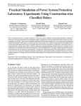
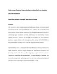
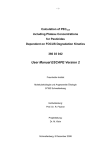
October 21st, 2004
The TEC Interlock & Slow Control System Answers to the Questions in the Controls User
Requirements Document
W. Beaumont, W. Karpinski, K. Klein and N. Lumb
Abstract
This document contains the answers of the TEC community to the questions raised in the document
“Tracker Control System - Requirements Specification” by E. Carrone and A. Tsirou. Both the interlock systems necessary in the two institutes responsible for the TEC assembly 1) and the interlock and
slow control for the final TEC in the CMS detector, are discussed.
Version 1.0
1)
1. Physikalisches Institut B, RWTH Aachen
Institut de Physique Nucléaire de Lyon, Université Claude Bernard Lyon-1
Contents
1 Introduction
2
2 Question 3.1: Goals
2
3 Question 3.2: Input and output requirements
3
3.1
3.2
Input . . . . . . . . . . . . . . . . . . . . . . . . . . . . . . . . . . . . . . . . . . . . . . . . . .
4
3.1.1
Input to the interlock . . . . . . . . . . . . . . . . . . . . . . . . . . . . . . . . . . . . .
4
3.1.2
Input to the slow control . . . . . . . . . . . . . . . . . . . . . . . . . . . . . . . . . . .
4
Output . . . . . . . . . . . . . . . . . . . . . . . . . . . . . . . . . . . . . . . . . . . . . . . . .
4
4 Question 3.3: Data requirements
5
5
Question 3.4: Functional requirements
5
5.1
Cases for a hardware interlock (PLC) . . . . . . . . . . . . . . . . . . . . . . . . . . . . . . . .
5
5.2
Cases for a software interlock (slow control) . . . . . . . . . . . . . . . . . . . . . . . . . . . .
7
6 Question 3.5: Performance requirements
8
7 Question 3.7: System security requirements
8
8 Question 3.8: Back up and recovery requirements
8
9 Question 3.9: Support considerations
9
10 Question 3.10: Hardware requirements
9
10.1 Question 3.10.1: Hardware functionality . . . . . . . . . . . . . . . . . . . . . . . . . . . . . . .
9
10.2 Question 3.10.2: Hardware characteristics . . . . . . . . . . . . . . . . . . . . . . . . . . . . . .
9
11 Question 3.11: Software requirements
12
11.1 Question 3.11.1: Software functionality . . . . . . . . . . . . . . . . . . . . . . . . . . . . . . .
12
11.2 Question 3.11.2: Software characteristics . . . . . . . . . . . . . . . . . . . . . . . . . . . . . .
13
12 Question 3.12: Usability requirements
13
1
1 Introduction
This document contains the answers of the TEC community to the questions raised in the document “Tracker Control System - Requirements Specification” by E. Carrone and A. Tsirou [1]. Both the interlock systems necessary
in the two institutes responsible for the TEC assembly, the 1. Physikalisches Institut B, RWTH Aachen, and the
Institut de Physique Nucléaire de Lyon, Université Claude Bernard Lyon-1, as well as the interlock and slow control for the final TEC in the CMS detector, are addressed.
In particular, points concerning PLC hardware and software aspects and the slow control based on the information
from the sensors are considered. Data acquisition (DAQ) issues (e.g. details of the DCU readout) are not discussed
here.
The order of the answers follows the order of the questions, which is not necessarily a logical order. The most
important issues are addressed in Sect. 10.2 (question 3.10.2: type and quantity of sensors), Sect. 5 (question
3.4: discussion of possible failures with suggestions of cuts and actions for the interlock) and Sect. 11.1 (question
3.11.1: software functionality).
To improve the readability of this document, the questions are repeated before each answer (italic font).
2 Question 3.1: Goals
Provide a clear list of the expectations of a new system or function(s), both in term of what must be improved and
what must be retained from the current processes. All detailed requirements should address one or more of these
goals.
It is not the purpose of this document to provide a description of the CMS tracker interlock and control system, in
particular since a lot of details are still under discussion. Here we just summarize shortly our understanding of the
architecture of the interlock/slow control system:
• The interlock (safety) system takes care of keeping the TEC in the best safe condition and bringing the
TEC or a part of it back into safe condition if a certain measured parameter exceeds a given threshold. This
functionality is done independently of any other system or user control, and should be built from components
that have a high reliability. The interlock of the tracker will be based on PLC technology. Although the cost
per sensor channel is high, it must be ensured that enough information is passed to the PLC to identify all
possible major disasters and react accordingly.
• The slow control safety system is a part of the slow control program that continously monitors all available
parameters. It can take decisions to intervene the regular operation of the system (software interlock) and
will communicate with the run control. As long as the slow control system is working, the interlock should
be redundant. For the slow control safety system much more channels will be available than for the interlock,
providing a detailed picture of a possible problem and allowing for a more specific reaction.
• Detailed monitoring of the module temperatures based on the DCU readout will be integrated into the data
acquisition. This information can help to identify the source of a problem, and consequently can also be
used as an input for a software interlock.
• Control of the bias voltage will be handled either by the run control or the slow control program, while the
low voltage will be under control of the CMS Detector Controls System, which works under PVSS. The
slow control system will be interfaced to the CMS Detector Controls System.
• There will be an interface to the CMS Detector Safety System.
An interlock and slow control/monitoring system shall be provided for three systems of different complexity:
• System 1: one tracker end cap (TEC) at the 1. Physikalisches Institut B, RWTH Aachen, operated at room
temperature and at −20 ◦C using a commercial cooling plant.
• System 2: one tracker end cap at the Institut de Physique Nucléaire de Lyon, Université Claude Bernard
Lyon-1, operated in a cold room at room temperature and at −20 ◦ C ambient temperature.
• System 3: the two tracker end caps in the CMS detector.
2
In principle there could be yet another system: it is forseen that the two tracker end caps will be operated and
debugged at building 186 before being inserted into the CMS detector at point 5. This system is not treated separately here, since it must clearly be as close as possible to the final system already and thus will be very similar to
system 3.
It must be stressed that, while system 3 is very well defined, systems 1 and 2 will envolve from small scale systems,
consisting of one petal, to large systems, consisting of a full tracker end cap (although only a part, at most one
sector comprising 18 petals, of each TEC will be powered and readout at once). The interlock and slow control
system (both hardware and software) provided must be scalable from the beginning to cope with this evolution.
Most requirements mentioned in the following are common to all three systems. If there are special requirements
for one of the systems, this is stated explicitly.
A very simplified and schematic view of the interlock and slow control scheme of the TEC is shown in Fig. 1.
MS cables
TEC
568 temperature sensors
18 humidity sensors
72 DCUs on CCUM
18
576 temperature sensors
72 humidity sensors
6400 temperatures, currents, voltages, ...
DCUs on modules
status and temperature information
72 channels
Chiller
PS
currents and voltages
cold
room
status information etc.
light
sensor
alarm
gas
flow
flow rate
DCS
radiation, CMS gas & cooling system
PLC
interlock
log file
SMS
local
shift expert
slow control
RCMS
WWW
FEC
database
communication/control
action from interlock
flow of information
Figure 1: Very simplified and schematic view of the interlock and slow control scheme. Completeness is claimed
neither for input information nor for other dependencies. In particular, actions from the slow control are not shown,
but are in principle similar to the actions from the interlock. The number of channels correspond to one TEC.
3 Question 3.2: Input and output requirements
Provide a description of all manual and automated input requirements for the control system such as data entry
from sensors, probes and/or other interconnected systems, as well as all output requirements for the control system
such as printed forms, reports, display screens, files.
3
3.1 Input
3.1.1 Input to the interlock
Input data will come from:
a.) Temperature sensors: one resistance value per sensor.
b.) Humidity sensors: one voltage per sensor. The power for these sensors will have to be provided, and it has
to be assured that bad measurements due to a failing power supply will be identified by the interlock and
slow control system.
c.) Cooling machine: in system 2, the Louvain cooling machine will provide the nominal and actual temperature,
as well as status information [2]. In system 1, due to the lack of a cold room, a commercial cooling machine
will be used. Documentation will be provided as soon as possible.
d.) Information from a sensor monitoring the light intensity when HV is on.
In the case of system 1, there will be additional input from:
e.) The clean room status.
f.) A sensor monitoring the water level on the clean room floor.
g.) Flowmeter measuring the flow of the Nitrogen or dry air.
h.) Flowmeter measuring the flow of the cooling liquid.
In the case of system 2, the following additional inputs should be anticipated:
e.) Temperature and humidity information from sensors monitoring the cold room atmosphere.
f.) Status information from the cold room control system (RS232 link - see [8]).
g.) Inputs from sensors monitoring the cold room door status (open or closed).
h.) A central emergency button.
For system 3, there will of course be additional information from the cooling and gas systems, the radiation
monitor, the thermal screen etc.
The important question of how many channels shall be used in the interlock is discussed in section 10.2.
3.1.2 Input to the slow control
All information going into the interlock can be requested by the slow control. In addition, the slow control will
get input from the power supplies: three voltages (2.50 V, 1.25 V, bias voltage) plus their currents will be provided
by the CAEN power supplies. As discussed in Section 10.2, it will be sufficient if this information is used for the
slow control, there is no reason why this information should go into the PLC.
3.2 Output
All information should be read regularly. The values should be written into a log file, to assure that they will be
kept even in the case that the slow control fails or is not operational, stored in a data base, as well as being displayed
on the screen (both the real-time values and the history).
Information should be read frequently, typically every minute, if possible. This time interval must be changeable
by the user individually for each sensor (within a sensible pre-defined range).
4
4 Question 3.3: Data requirements
Identity the data elements and logical data groupings that will be stored and processed by the control system.
Include archiving data requirements and sensitivity of data.
All available information must be logged and archived in a data base.
Easy access to all information is necessary, i.e. a user interface must be provided to browse the data base.
A tool to display archived data (e.g. temperature versus time) must be provided.
Data must be stored in common format (e.g. ascii, XML, or any well documented, easily readable binary format)
such that tools for further analysis can be developed by the users (e.g. with Root).
5
Question 3.4: Functional requirements
Delineate, at a detailed level, control system requirements within the context of the processes it must support. This
is supported by a process model, which may be included, where all the actions to be performed by the process
control are to be specified. This section also includes the controls in terms of “IF .. THEN” events handling.
Under certain conditions, the interlock should take action, i.e.
a.) ramp down the bias voltage and/or send a signal to the low voltage control system to switch off the low
voltage;
and/or
b.) act on the cooling system, i.e. switch off or ramp down/up the cooling machine for systems 1 and 2; act on
the cold room for system 2; give feedback to the tracker cooling system or, if this is possible, close valves to
certain cooling loops for system 3;
c.) act on the dry gas flushing system.
In the following, a list of failures is given. For each failure, the cuts on which the interlock should react are listed
and the demanded reaction is outlined. The list is neither exhaustive nor final. In particular for the cuts, it is felt
that at the moment no numbers (temperatures, humidities, change rates) can be given. Clearly, some experience
with stability and uniformity of the temperature and humidity inside the tracker is necessary here. These numbers
shall anyway be easily changeable by the expert user.
Also the reaction time still has to be specified; it of course depends directly on the frequency of sensor readings
that can be implemented.
This discussion is divided into two parts: in section 5.1, it is assumed that the tracker relies on the hardware
interlock from the PLC. In section 5.2 then the same failures are listed for the case that a software interlock is
available as well.
5.1
Cases for a hardware interlock (PLC)
a.) Global cooling failure
– The PLC should get information from the chiller for system 1, the cold room and chiller for system 2,
and the global cooling system for system 3.
– Cut on the mean temperature T of the temperature sensors that are connected to the PLC, and the
change of the temperature d T /dt.
– Action: for the whole system (TEC), the LV should be switched off and the HV ramped down.
b.) Global stop of Nitrogen flow
– For system 3, the PLC should get information from the gas flushing system. In systems 1 and 2 the gas
flushing system will provide information as to whether the gas is flushing or not, as well as (for system
2) the dew point temperature for gas arriving at the TEC.
– Cut on the mean relative humidity H, and the change of the humidity d H /dt, as well as H and
dH/dt of the sensors nearest to the N 2 outlet.
5
– Action: if either the gas flushing stops or one of the above cuts is met, the HV of the whole TEC should
be ramped down. To avoid condensation, for systems 2 and 3 the TEC should be warmed up in case
the temperature comes close to the dew point (i.e. a signal must be send to the chiller for system 1
and to the cold room and Louvain cooling plant for system 2). For the system 3, this is not desirable,
and hopefully not necessary, since there should be some redundancy in the Nitrogen system (to be
confirmed by experts).
c.) High radiation level
– For system 3, the PLC should get information from the radiation monitor
– The beam dump (which is independent from the PLC) should fire.
– Action: LV should be switched off and HV ramped down for the whole TEC.
d.) Cooling problem in a single cooling loop
– As explained in Section 10.2, sensors of pairs of petals belonging to one cooling loop should be connected in parallel (with exception of disks 9). If there is a problem with the whole loop, the temperature
of all channels corresponding to this loop will increase. If the problem is on the pipes going to one
single petal, the increase will be visible on this petal only, and thus only on one temperature channel.
– Cut on the mean T and dT/dt of a system of two petals.
– Action: LV and HV of the affected petals should be ramped down.
– If C6 F14 sniffers are available and measure an increase of the C 6 F14 concentration, there is probably a
leak, and thus the valve to this cooling loop should be closed after the LV and HV is ramped down.
e.) Short on a module:
– HV should trip → no interlock necessary. The software should take care that continous re-ramping is
avoided.
f.) Local cooling problem of one module: will hardly be detectable with the limited numbers of sensors → rely
on slow control.
g.) Light level too high
1.) Problem: an attempt is made to raise the HV when the photo-sensor in the test room detects that the
light level is high.
- Action: the interlock sends a signal to all HV supplies to inhibit ramping, and an error message is
returned.
2.) Problem: a non-zero HV value is applied on one or more modules and the light level is detected to be
too high.
- Action: HV is ramped down on all modules.
h.) Cold room door open during cooling (relevant for system 2)
1.) Problem: an attempt is made to reduce the cold room temperature (system 2) when one of the doors is
detected to be open.
- Action: Inhibit on ramping down of temperature; error message.
2.) Problem: one of the cold room doors is opened while the room is at low temperature.
- Action: HV ramped down; LV switched off; cooling plant and cold room temperatures ramped
up; audible alarm.
i.) A non-specific, unforseen emergency situation develops
– Some kind of “general emergency off” must be implemented. In case of system 2, a signal is sent to
the PLC by means of a LARGE RED BUTTON situated in the control room.
– Action for systems 1 and 2: LV switched off and HV ramped down; cooling plant and cold room
temperatures ramped up.
– Action for system 3: LV switched off and HV ramped down, other actions to be discussed.
6
5.2
Cases for a software interlock (slow control)
a.) Global cooling failure
– Spotted fastest with the slow control by monitoring the hybrid temperature.
– Similar cuts on all available information:
∗
∗
∗
∗
Hybrid temperature (DCU readout): T, d T /dt.
Silicon temperature (DCU readout): T, d T /dt.
Pipe temperature (DCU on CCUM readout): T, d T /dt.
MS cable readout: T, d T /dt.
– Action: LV and HV of the whole TEC should be ramped down.
b.) Global stop of Nitrogen flow
– Cuts: as for the PLC case, taking into account all available humidity sensors (DCU on CCUM readout):
H, d H /dt and H and dH/dt for sensors near Nitrogen inlet.
c.) Cooling problem in a single cooling loop
– With more information available, it will be possible to decide if the problem concerns the whole loop
(all petals get hot) or only one petal (only this petal gets significantly hotter).
– If only MS cable information is available: if T or d T /dt of one petal is high, ramp down power
of this petal. If T or d T /dt of more than one petal is high, ramp down LV and HV of loop.
– If control power is on: reading the temperature sensors on the cooling inserts will give a clear picture
on how many petals are affected.
– If analog power is on: reading out the DCU, it can be decided if all petals, one petal or even only one
module (local problem) is affected.
d.) Local cooling problem
– Problems with the cooling of single modules can only be identified with the analog power on.
– Cut on T, dT/dt of a single module
– Action: switch off HV of this module (this might affect another module of the same ring (always a
neighbour in φ), depending on the modules position) and choose APV parameters that lead to minimal
power consumption. If the temperature is still too high, the LV would have to be switched off as well.
This however affects a larger number of modules (up to 11).
It would be diserable for systems 1 and 2 to have a general on/off switch for the endcap, to avoid confusion if
people work locally (doing hardware work), while at the same time others work remotely (trying to take data).
Such a switch should be visible and setable both virtually in the software and physically in the room where the
TEC is operated.
In systems 1 and 2, additional environmental sensors (requested in chapter 3.10.2) could be used in the interlock,
if necessary. They could e.g. be used to calculate the dew point, using a humidity sensor, a temperature sensor
measuring the air temperature, and a temperature sensor attached to a cooling pipe. Then an interlock could be
issued in case the coldest temperature is close to the calculated dew point. In this case, the HV should be ramped
down, and the temperature should be increased to room temperature.
In systems 1 and 2, if the chiller raises an alarm, all voltages should be ramped down and the chiller should be
switched off.
One general problem is how to avoid that interlocks are caused by bad sensor readings due to cable failures. In
cases where broken cables can lead to physical values, cross checks should be forseen for the slow control (reading
of sensors that are close in space).
Of course a lot of questions, especially concerning redundancy of the system (failure of communication with the
cooling plant, failure of communication with the DCS etc.) have not been adressed here and have to be discussed
with the experts.
7
6 Question 3.5: Performance requirements
Portray owner/user defined standards for system operations, relating to volumes and growth.
The systems 1 and 2 will be growing systems in the sense that they will consist of one petal in the beginning and
144 petals in the end. Thus the hardware and software must be highly scalable, allowing for any number of petals
between these extremes. Adding and removing petals must be straightforward to the user, both soft- and hardware
wise. Such a system will then automatically be usable for system 3 as well.
Another point is that at the moment it is unknown how many PSU will be available for systems 1 and 2 during
assembly. It must however be assumed that only a small subset of the PSUs needed for the readout of a complete
TEC will be available. Since it should nevertheless be possible to read sensors from the whole TEC, a patch panel
must be provided to which the multiservice (MS) cables that are not attached to a power supply can be connected.
From this patch panel the temperature and humidity signals must be wired to the electronics cards that include the
current source, conditioning etc., from which the signals go finally to the PLC.
Another related problem is the following: at the moment it is planned that humidity sensors connected to the MS
cable are present only on the backpetals mounted on the 6 and 12 o’clock positions (Sect. 10.2). From the point
of view of environmental control it would therefore be preferable to assemble these petals on the disks first. At
the present state it is however not decided in which order to mount the petals on the mechanical structure. A few
additional environmental sensors are therefore needed to be in any case independent from this order.
The required response time for the interlock is of the order of a few seconds (exception: high radiation level, but
here the beam dump system should react anyway).
7 Question 3.7: System security requirements
Provide details of the security classification of the data handled by the system, special handling required for the
data, and the types and levels of protection and control required for user access to the data.
Data are not very critical, therefore no special safety measures are necessary for their access. Of course all data
values, user input and changes to the system must be logged and archived.
However, certain changes in the software (e.g. change of cuts) should only be allowed for expert users. User
privileges should be defined on a per-user basis. Maybe one can define some kind of “expert login”, under which
then changes can be applied by the expert. Changes should be allowed only if the system is in a safe state (e.g. HV
off), especially not during a run.
In case remote control of the interlock or slow control system, e.g. via web based techniques, will be necessary
(virtual counting room for system 3), a lot of attention must be paid to security issues. Access via the internet
must be absolutely safe. In case the system is controlled via internet and the network connection is lost, a recovery
mechanism must be executed in order that the system is kept in or brought back to a safe state. Remote control of
the PLC should not be allowed when there is no local shift expert available at point 5.
The computers of the interlock/slow control system should be part of a network protected by a firewall from the
outside world and open only to CMS users (e.g. the CMS network).
The PLC should not receive any input information for its interlock decision via the network, instead point-to-point
connections or industrial buses should be used.
8 Question 3.8: Back up and recovery requirements
Provide details of back up and recovery requirements.
The interlock system must of course survive a power cut. Therefore an uninteruptable power supply (UPS) has to
be provided for the PLC.
Data stored inside the PLC during a power cut must be accessible after power recovery (automatically copied from
PLC to the usual places like the data base etc.).
In case the interlock was active during the power cut (e.g. power was cut only on the cooling system and the PCs,
and the interlock cut the power to the power supplies), one needs some kind of report after recovery, i.e. a kind of
log file which explains what happend during the time of the power cut. In general it would be enough only to log
changes of values and actions taken, together with a time stamp.
Of course also the interlock system itself can fail. For this reason, the interlock signals to the power supplies
should be ON (i.e. non-zero) for the PS to work, such that when the PLC fails the power supplies are interlocked.
Self-recovery of the interlock system should be inhibited.
8
9 Question 3.9: Support considerations
A description of any special or unusual support considerations that this system or component might require.
The first version of the interlock software should be installed by the person responsible for the software, and an
expert should verify that the system is working properly.
In case of software updates, it should be verified that the update acts correctly (correct sensor and PS adressing
and correct actions taken), before the new version is used. In case of problems, it should be easy to go back to the
previous software version.
Experts should of course be reachable via e-mail and respond within a reasonable time scale.
A mailing list, where questions and problems that might be interesting for all users can be discussed, would be
very useful.
Spares for all crucial parts (PLC, UPS) must be available.
10 Question 3.10: Hardware requirements
10.1 Question 3.10.1: Hardware functionality
This section should cover the required capabilities of the hardware, e.g., requirement for the hardware to support
multiple operating systems, or must support Ethernet, PROFIBUS, as well as SMS messaging systems.
The PLC should be connected to the network via ethernet. It needs RS232 support for communication with e.g.
the cooling machine, and maybe CAN support for communication with the power supplies.
Cabling to the PLC should be clear and structured, e.g. printed circuit boards with current sources, conditioning
etc. on board could be provided, to which the user then can easily connect the temperature and humidity sensors.
For the assembly, C6 F14 sniffers would be very useful.
Warning and alarm messages should be send to an on-call experts mobile phone via SMS.
10.2
Question 3.10.2: Hardware characteristics
Required characteristics of the hardware. E.g. what type of sensors and actuators you will be using, what type of
valves and/or flow meters, etc.
The following types of sensors will be accessible via the TEC multiservice (MS) cables:
1.) Thermistors of type NCP18XH103F03RB (old type number NTH5G16P33B103F07TH) from Murata [3].
2.) Humidity sensors of type HMX2000 from Hygrometrix [4].
These will be accessible “always”, i.e. independently of the front-end electronics power.
The number of temperature sensors per petal are the following:
• Front petals, disk 1-3: six temperature sensors per petal
• Front petals, disk 4-6: six temperature sensors per petal
• Front petals, disk 7-8: five temperature sensors per petal
• Front petals, disk 9: four temperature sensors per petal
• Back petals, disk 1-3: three temperature sensors per petal
• Back petals, disk 4-6: two temperature sensors per petal
• Back petals, disk 7-8: two temperature sensors per petal
• Back petals, disk 9: two temperature sensors per petal
In addition, one relative humidity sensor will be present on each back petal mounted on a 6 or 12 o’clock position
on the disk.
A detailed description of the positions of the temperature and humidity sensors can be found in Ref. [5].
9
With 144 petals per end cap (72 front and 72 back petals), this makes a total of 18 humidity sensors and 568
temperature sensors per end cap. All these sensors should be read out and used for the slow control. For the
interlock, all 18 humidity sensors should be used. However, due to the high cost per PLC channel, not all of the
temperature sensors can be used in the interlock 1) .
The physical substructure to be considered in the interlock is a cooling loop. Each end cap consists of nine disks
(Fig. 2). On each disk eight front and eight back petals are mounted. The nine (front or back) petals that are
mounted on the same φ-position on the disks (i.e. one petal per disk) make up one so-called “tower”. The petals of
one tower are arranged in two independent cooling loops. The main cooling pipe of each loop runs in the beam pipe
direction, and connects petals mounted on different disks. There are two types of cooling loops: loops connecting
petals of disks 1, 3, 5, 7, and loops connecting petals of disks 2, 4, 6, 8, 9. Consequently in each end cap there are
32 independent cooling loops, each with 4 or 5 petals connected in parallel.
The number and combination of temperature sensors to PLC input channels is intimately connected to the question
of the granularity of the PS interlock, i.e. the number of available PLC output channels. Following the information
given in [6], we assume the following:
• One power supply unit (PSU) comprises one low voltage and two high voltage channels. Two PSUs are
sitting in one card, the power supply module (PSM).
• Power supply units are arranged in crates. Up to 18 units (9 PSM) fit into one crate.
• Per crate, three local and one global interlock is available.
• Three power supply units are necessary for petals of disks 1-6, two for petals of disks 7-9.
• Cooling loops with petals of disks 1, 3, 5, 7 need 3+3+3+2=11 PSUs, cooling loops with petals of disks 2,
4, 6, 8, 9 need 3+3+3+2+2=13 PSUs.
Figure 2: Technical drawing of one tracker end cap, with the interaction point to the right.
1)
If conditioning of signals is necessary, the same hardware should be used both for sensors that go to the interlock and others
that are used only for the slow control.
10
Crate 1 with 17 PSU
FP
FP
FP
Disk1
Disk 3
Disk 5
FP
FP
Disk 7 Disk 2
Interlock 2
Interlock 1
FP
Disk 4
Interlock 3
Crate 2 with 17 PSU
BP
BP
BP
Disk 1
Disk 3
Disk 5
Interlock 4
BP
BP
Disk 7 Disk 2
BP
Disk 4
Interlock 6
Interlock 5
Crate 3 with 14 PSU
FP
Disk 6
FP
BP
Disk 8 Disk 6
Interlock 7
BP
FP
BP
Disk 8 Disk 9 Disk 9
Interlock 8
Interlock 9
Figure 3: Suggestion for the arrangement of petal low voltage channels into crates, and correspondence of power
supply units to interlock channels.
Based on this information, we suggest the arrangement of petal low voltage channels into crates shown in Fig. 3.
The four cooling loops of two neighbouring towers (where the front and back petals of the two towers make up FEC
control loops) are arranged in three crates. This pattern is repeated eight times per end cap. The three interlock
channels that are available per crate can be arranged in a way that each channel interlocks two petals from the
same cooling loop, with the exception of interlock channel 9. The only disadvantage of this arrangement is that
the crates are not 100% utilized. In our suggestion 24 crates are needed per end cap, while with 100% utilisation
only 22 crates would be needed per end cap.
We assume here that the control power supplies will be contained in separate crates. Per sector (two neighbouring
towers), nine PSUs are needed for the control.
With one interlock channel for two petals belonging to one cooling loop, we suggest to choose one temperature
sensor per petal (preferably the one connected to a module of ring 5, since this is the most critical module type in
terms of cooling requirements 2) ) and to connect these two sensors in parallel. The necessary electrical connection
could easily be done in the cavern at patch panel 2. In this way the number of PLC input channels equals the
number of (local) output channels, i.e. 72 per endcap.
It is expected that during assembly of systems 1 and 2 much fewer PSUs than the necessary 432 will be available.
We hope that there will be at least enough PSU to operate a sector consisting of two towers or 18 petals (48 PSUs
for the analog and 9 PSUs for the digital power). In the above arrangement, this would correspond to three crates
for the analog power and 13 interlock output channels from the PLC (four global and nine local).
In case a sensor fails with time, it should be possible to connect another one instead. For system 3 this means in
particular that all wires have to be accessible (low radiation level).
For monitoring purposes, all sensors should be read.
When the controls power is switched on, information from additional sensors becomes available via the DCU on
the CCUM. The thermistors used are of another type:
3.) Thermistors of type NTSD0XH103FE1B0 from Murata [7].
There are four thermistors present per petal, glued to cooling inserts that are in contact with the cooling pipe. In
addition, on front petals one humidity sensor will be read out by the DCU on the CCUM. Details can again be
found in [5]. This makes an additional 72 humidity sensors and 576 temperature sensors per end cap. Since this
information is read out by the CCU, it falls more in the area of data acquisition. This information will not always
2)
In case there will be a problem with ring 5 (thermal runaway), a different module geometry could be chosen at patch panel 2.
11
be available, and therefore will not be used for a (PLC) interlock. However, it will be used for slow control and
thus for a “software interlock”.
Finally, with low voltages applied to the modules, the information from the DCU on the front end hybrid can be
accessed. The thermistors, present both on the Kapton strip close to the sensor and on the hybrid, are again of
type 1.). In addition to the silicon and hybrid temperature, the DCU temperature, leakage current and low voltages
can be read via the DCU.
For system 2, information from the Louvain chiller will also be available [2]. This information is accessible via a
RS232 interface.
A commercial chiller with high cooling power will be used in system 1. A reference will be provided as soon as
possible.
It is assumed that the CAEN PSs will be used during the TEC integration phase. These will provide information on
the voltages and currents (for 2.50V, 1.25V, bias voltage). Since the PSs have built-in over-voltage and over-current
protection, the voltage and current signals do not need to be used as inputs for the PLC, only for the slow control.
System 2 will be operated in a cold room, running at an ambient temperature of −20 ◦C. Certainly the PLC needs
to be interfaced to the controls of this cold room [8].
For system 3, the PLC will receive additional information from the cooling and gas flushing system, the thermal
screen as well as from more external systems such as the radiation monitor. This information is not specific to the
TEC and therefore not described here.
Finally, a relatively small number of additional environmental sensors will be needed for the systems 1 and 2, to
have a monitoring independent of the status of the petal mounting, cabling etc. Five humidity sensors (could be of
type Honeywell) and twenty temperature sensors (thermistors or PT100s) per center would be enough.
11 Question 3.11: Software requirements
11.1
Question 3.11.1: Software functionality
This section should cover the required capabilities of the software, e.g. databases, operating systems, communications (remote access), diagnostics.
There must be an “interlock software” that runs on a terminal connected directly to the PLC. This would be a standalone programm independent of the DAQ, and should run no matter if there are DAQ problems, network problems
etc. However, under normal circumstances, the PLC and the slow control should be accessible via the RCMS, i.e.
both the PLC as well as the reading of other sensors (DCU, but also multiservice cables, plus PS control) should
be embedded into the run control environment. Then, the DAQ and the slow control could be controlled from one
PC, and in fact the run control could be used as interface for monitoring and slow control.
Before getting active, the PLC should perform some kind of self-check. This could perhaps be forced by loading
up a configuration file that contains the sensor list, cut values etc. This file could be checked, i.e. funcionality of
listed hardware pieces (communication with external devices such as the chiller, are sensor values and cuts sensible, etc.)
Since for the DAQ PCs running under the linux operating system are usually used, the controls software should
also run under linux, in particular it should work with the same version of the operating system. In general, it
should as much as possible be independent of the operating system. In case that single pieces of hardware or software (e.g. the OPC server of the PLC) can only run under Windows, an interface should be provided that makes
remote control from a linux PC possible.
Software should be configurable by the user, i.e. the cuts, number of sensors, calibration constants etc. should be
changeable by the user. It should be possible to do these changes in a wrapper software, e.g. using a user interface,
or via an XML file, or using a software written in a standard programming language (e.g. C++, Java), not in the
PLC programming language.
There should be online displays of all measured parameters (temperatures, humidities, status) used in the interlock.
For temperatures and humidities, the history over a certain time must be displayed graphically. This history time
must be choosable by the user. Also it must be possible to choose the scales of all graphs individually, and to zoom
into them. It would be most practical if the software would automatically adjust the scale in a sensible way.
A picture showing graphically the location of sensors (and a possibility to get the position of a certain sensor value
by clicking on its graph and vice versa) would be useful.
The PLC monitoring software could also run on a separate PC connected to the PLC (powered also by the UPS).
All data should be stored in a data base. The database must be browseable, i.e. a user interface must be provided.
It must be kept in mind that the systems 1 and 2 will be maintained also by non-expert personnel (technicians),
while in system 3 shifts will probably be done by non-expert physicists. This has the consequence that in case of a
12
problem it must be absolutely clear what to do, i.e. messages should pop up that say what happened (i.e. why the
interlock fired) and give instructions how to react. For maximum flexibility, the user should be able to define such
messages himself. Measures should be taken to avoid “wrong” actions for system recovery (e.g. ramping up the
low voltages again after the interlock fired should only be allowed for experts).
11.2 Question 3.11.2: Software characteristics
Required characteristics of the software, e.g. reusability of code, packaging.
Ideally, the software should be scalable, i.e. the software provided for the operation of the systems 1 and 2 should
be very similar (with less functionality) to the software used for system 3. Software written by the user should be
re-usable as well.
12 Question 3.12: Usability requirements
This section should define the requirements associated with ease of use, including menu structures, screen/window
designs, screen colors, screen navigation, maximum input lines per screen, query capabilities, unattended installation, report layouts, online help and other interfaces to users and/or supervisors.
An installation package or script would be helpful.
The software should be accessible via a CVS server such that updates are easily possible.
A mailing list for all software/hardware developers and users could be very useful. There e.g. software updates
could be posted.
The software must be open source to allow for user changes/patches/debugging.
References
[1] E. Carrone, A. Tsirou, Tracker Controls System, Requirements Specification, CERN EDMS CMS-TK-OP0001 (April 2004).
[2] Louvain cooling plant user manual, available from the Louvain group, Institut de Physique Nucléaire, Chemin
du cyclotron, 2, B-1348 Louvain-la-Neuve.
[3] http://www.murata.com/catalog/r44/el0770 −1.pdf
[4] http://www.hygrometrix.com/DSHMX2000D%20pc%20closed%20bridge.pdf
[5] W. Karpinski, Temperature and Humidity Measurements in TEC (25th of June, 2003).
[6] A. Tsirou, Controls Installation for: the Thermal Screen, the Interlock System and the permanent Monitoring
System, http://agenda.cern.ch/askArchive.php?base=agenda&categ=a043067&id=a043067s1t3/transparencies
[7] http://www.murata.com/catalog/r44/el0780 −1.pdf
[8] Documentation of GTHERM company, available from IPN-Lyon.
13