1
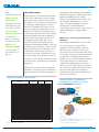
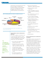
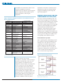
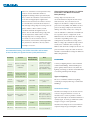
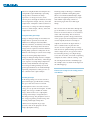
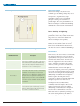
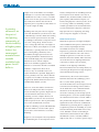
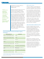
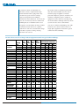
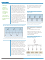
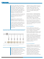
PQ TechWatch A product of the EPRI Power Quality Knowledge program Power Quality in Medium and Large Commercial Buildings November 2007 Chuck Thomas, Senior PQ Engineer, EPRI CONTENTS Introduction . . . . . . . . . . . . . . . . . . . . . . . . . . .1 Major Uses of Energy in Commercial Buildings . . . . . . . . . . . . . . . . .1 Typical Electric Loads of Commercial Buildings . . . . . . . . . . . . . . . . .2 SUMMARY According to the European Union, 40% of all electric energy produced in Europe is used to power commercial and residential buildings. Commercial buildings include nonresidential, Power Quality Impact on Commercial Customers . . . . . . . . . . . . . . . .2 nonindustrial buildings such as hospitals, office and apartment Heating, Ventilation, and Air Conditioning System (HVAC) . . . . . . . . . .3 arenas. Within those buildings, HVAC units, PCs, fax machines, buildings, hotels, schools, churches, stores, theaters, and sports copiers, and printers are now sharing the building wiring system with Air-Conditioner Systems . . . . . . . . . . . . . . .3 electronic fluorescent lighting, adjustable speed heat pumps, and Process Cooling Water (Chillers and Water Pumps) . . . . . . . . . . . . .4 Ventilation Systems . . . . . . . . . . . . . . . . . . .5 various electronic communications equipment. While electronicbased commercial equipment increases productivity, this type of equipment can often be adversely affected by poor power quality. Protection of HVAC Voltage-Dip-Sensitive Components . . . . . . . . . . . . . . . . . . . . . . . .5 Building Automation Systems . . . . . . . . . . .6 Variable-Speed Drives for Ventilation and Water Pumps . . . . . . . . . . . . . . . . . . . .7 General Recommendations for Chiller Controllers and Motor Protection Relay Settings . . . . . . . . . . . . . . . . . . . . . . .9 Lighting . . . . . . . . . . . . . . . . . . . . . . . . . . . . . .9 Types of Lighting . . . . . . . . . . . . . . . . . . . . .9 Power Quality and Lighting . . . . . . . . . . . .11 Elevators . . . . . . . . . . . . . . . . . . . . . . . . . . . .14 Harmonic-Generating Loads . . . . . . . . . . . .14 Today, the quality of electric power generation, transmission, and distribution systems is very high. With the exception of conditions associated with brownouts, most utilities deliver well-regulated power to all but the most extremely remote customers. However, power dips and surges are still of concern, largely because of the potential impact for electronics damage and interference with computer operations. Another power quality issue that must be kept in mind is the production of harmonic currents by nonlinear equipment, such as office equipment, lighting, and some HVAC systems. This PQ TechWatch takes an in-depth look at some of the larger Lighting and Three-Phase Loads . . . . . . . .16 components of commercial operations, including HVAC, lighting, Wiring Configurations in Commercial Buildings . . . . . . . . . . . . . . . .17 office equipment, and elevators. The intent of this document is to Harmonic Effects on Building Wiring . . . . .18 mitigation techniques can be applied to minimize shutdowns and Notes . . . . . . . . . . . . . . . . . . . . . . . . . . . . . . .20 show how power quality impacts commercial equipment and what equipment damage. About the EPRI Power Quality Knowledge program The EPRI Power Quality Knowledge program provides a wealth of resources in well-designed, readable, and accessible formats. Paramount among these resources are documents covering a wide range of PQ topics, written not only for use by busy PQ professionals, but also to be shared with important end-use customers and internal utility managers. The program’s website, www.mypq.net, is the most comprehensive electronic PQ resource available, providing 24-7 access to proven expertise via the PQ Hotline, hundreds of PQ case studies, over 200 PQ technical documents, PQ standards references, indexes, conference presentations, and a wealth of other resources. For more information, please visit www.mypq.net. Copyright 2007, EPRI (www.epri.com). All rights reserved. Distribution of PQ TechWatch is subject to a license agreement with EPRI. No portion of this report may be reproduced or redistributed in any form, including electronic copies, without prior written consent from EPRI. Distribution outside the licensed organization is expressly forbidden. Product and company names mentioned in this document may be trademarks of their respective companies. Mention of third-party products is for informational purposes only and constitutes neither a recommendation nor an endorsement. EPRI and the EPRI logo are trademarks of EPRI. ii Power Quality in Medium and Large Commercial Buildings The proliferation in office use of electronic equipment and microprocessor -based controls has caused electric utilities to redefine power quality in terms of the quality of voltage supply rather than availability of power. INTRODUCTION Power quality has emerged as an important issue for the commercial customer segment. Historically, power quality issues have been the domain of electric utilities, which focused on reducing or eliminating power outages. However, the proliferation in office use of electronic equipment and microprocessorbased controls has caused electric utilities to redefine power quality in terms of the quality of voltage supply rather than availability of power. In this regard, IEEE Standard 11591995(R2001) Recommended Practice for Monitoring Electric Power Quality and its European counterpart IEC 61000-4-30 Testing and Measurement Techniques—Power Quality Measurement Methods have defined a set of terminologies and their characteristics to describe the electrical environment in terms of voltage quality. The table below shows the categories of power quality disturbances with spectral content, typical duration, and typical magnitude. This document focuses on how commercial equipment is affected by power disturbances. The term commercial building encompasses all buildings other than industrial buildings and private dwellings. It includes office and apartment buildings; hotels; schools; churches; steamship piers; air, railway, and bus terminals; department stores; retail shops; government buildings; hospitals; nursing homes; mental health and correctional facilities; theaters; sports arenas; and other buildings serving the public directly. Major Uses of Energy in Commercial Buildings Each principal building activity has its own set of characteristics (energy sources, equipment, number of workers, hours of operation) that contribute to total energy use. European research shows that 40% of the total energy used in the European Union (EU) is used in the residential and commercial building sector, and the breakdown of energy usage within that sector is shown below. 1 Commercial buildings alone account for about 12 percent of EU energy use. However, the study doesn’t show how the growth of the Internet and the proliferation of digital equipment has changed the dynamics of the electrical environment. Categories of Power Quality Variation Categories 1.0 Transients 1.1 Impulsive 1.1.1 Nanosecond 1.1.2 Microsecond 1.1.3 Millisecond 1.2 Oscillatory 1.2.1 Low Frequency 1.2.2 Medium Frequency 1.2.3 High Frequency 2.0 Short duration variations 2.1 Instantaneous 2.1.1 Sag 2.1.2 Swell 2.2 Momentary 2.2.1 Interruption 2.2.2 Sag 2.2.3 Swell 2.3 Temporary 2.3.1 Interruption 2.3.2 Sag 2.3.3 Swell 3.0 Long duration variations 3.1 Interruption, sustained 3.2 Undervoltages 3.3 Overvoltages 4.0 Voltage imbalance 5.0 Waveform Distortion 5.1 DC offset 5.2 Harmonics 5.3 Interharmonics 5.4 Notching 5.5 Noise 6.0 Voltage fluctuations 7.0 Power frequency variations Source: IEEE Std. 1159-1995 1 Typical Spectral Content Typical Duration Typical voltage Magnitudes Energy End Uses in the European Residential and Commercial Sectors EU Energy Use 5 ns rise 1 µs rise 0.1 ms rise < 50 ns 50 ns–1ms < 5 kHz 5 –500 kHz 0.5–5 MHz 0.3–50ms 20 µs 5 µs 0–4 pu 0–8 pu 0–4 pu 0.5–30 cycles 0.5–30 cycles 0.1–0.9 pu 1.1–1.8 pu 0.5 cycles–3 s 30 cycles–3 s 30 cycles–3 s < 0.1 pu 0.1–1.9 pu 1.1–1.4 pu 3 s–1 min 3 s–1 min 3 s–1 min < 0.1 pu 0.1–0.9 pu 1.1–1.2 pu > 1 min > 1 min > 1 min steady state 0.0 pu 0.8–0.9 pu 1.1–1.2 pu 0.5–2% steady state steady state steady state steady state steady state intermittent < 10 s 0.0–0.1% 0–20% 0–2% 0–100th H 0–6 kHz broad-band < 25 Hz Commercial and Residential Buildings 40% Commercial 30% Residential 70% 0–1% 0.1–7% The commercial building sector accounts for 12% of total European Union energy consumption. Source: European Commission Power Quality in Medium and Large Commercial Buildings Unfortunately, the EU study only shows total energy use and does not differentiate Elevators, moving stairways, dumbwaiters, and moving sidewalks electrical, natural gas, oil, and sustainable energy users. The figure below shows a Heating, ventilation, and air- conditioning breakdown of how electricity is used in commercial facilities in the United States. Garbage and rubbish storage and removal, incinerators, and sewage handling Hot- and cold-water systems and Electrical Energy End Uses in the U.S. Commercial Sector water treatment facilities Security watchmen and burglar alarms, electronic access systems Business machines, such as computers, calculating machines, and duplicating machines Refrigeration equipment Food handling and preparation facilities Building maintenance facilities Lightning protection Source: Commercial Buildings Energy Consumption Survey (CBECS), Energy Information Administration (EIA) Automated building control systems Entertainment facilities and specialized audiovisual and lighting Typical Electric Loads of Commercial Buildings systems Medical facilities The systems, equipment, and facilities used to satisfy functional requirements of large commercial buildings will vary with the type of commercial building but will generally include some, or all, of the following: The consequences of a disturbance may range from a minor nuisance to extensive equipment damage and loss of critical data. Power quality variations as described in the table on page 1 affect all categories of commercial customers. However, depending Interior and exterior lighting, both on the criticality of the equipment affected, utilitarian and decorative the consequence of the disturbance may Communications systems, such as range from a minor nuisance to extensive telephone, telegraph, computer link, equipment damage and loss of critical data. radio, closed-circuit television, code For example, a momentary voltage dip may call, public address, paging, impact the operation of an elevator and may electronic intercommunication, cause it to stop at a floor where it wasn’t pneumatic tube, doctors’ and nurses’ supposed to. In most cases, this is nothing call, and a variety of other signal more than a nuisance. However, the same systems voltage dip might instead cause an elevator Fire pumps and sprinkler, fire- detection, and alarm systems 2 Power Quality Impact on Commercial Customers controller to fail and may require a service call during which the elevator would be Power Quality in Medium and Large Commercial Buildings unavailable. The table below shows the list of generic equipment used in the commercial sector and the associated power quality symptoms and the primary power disturbances in both the commercial and industrial sites must be considered when designing a building or purchasing and operating equipment. quality disturbances affecting the equipment. HEATING, VENTILATION, AND AIR CONDITIONING SYSTEM (HVAC) Impact of Power Quality Disturbances on Commercial Sector Electrical Equipment 2 Electrical Equipment Air conditioning Audio system Computerized cooking equipment Copy machine Digital scale Digital thermostat Energy management Fax machine Fire/security system HVAC equipment Patient database computerized system ECG/EKG machine Elevators Computerized reservation system Simplex clock system ATM machine Gamma counter Check approval system Bar code scanner EEG/EKG machine Data processing Lighting control Power-Problem Symptoms Premature compressor failure Unit damage Unit damage Increased service calls Touchpad damage Increased service calls Unit damage Lack of control Unit damage Loss of control Unit damage No or poor communication False alarms Unit damage Increased service calls Compressor failure Increased service calls Data loss/data error Primary Power Quality Disturbance Category Voltage variation EMI/RFI Transients Transients Transients/EMI/RFI Transients/EMI/RFI Transients/EMI/RFI Transients/EMI/RFI Transients/EMI/RFI/voltage variations Voltage variation Voltage variation The largest commercial building load is the HVAC system. In addition to environmental controls for personal comfort levels, an HVAC system plays a vital role for buildings with data centers, which contain servers, personal computers, uninterruptible power supplies, and network and telecommunication equipment. Critical-facility loads are those loads that are vital to the operation of the building. Types of equipment that fall into the critical-facility group include air-conditioning systems, process cooling water (chillers and water pumps), and ventilation systems. Component damage Erroneous reading Component damage Increased service call Data loss/data error Voltage variation/transients Air-Conditioner Systems Voltage variation Incorrect time EMI/RFI Processing unit damage Incorrect data Unit damage Unit damage Increased service call Scanner damage Wrong scanning Unit damage Data loss/corruption Unit damage Brightness or dimness in lights Flickering of lights Transients Split- or packaged air conditioning systems are common in commercial buildings with multiple zones. The split-air systems are composed of two major components: the outdoor compressor/fan and the indoor furnace/ventilation units. In the split-air conditioner configuration, one HVAC unit is used to control the environment of one zone, as shown in the figure below. Voltage variation Voltage variations/transients Voltage variation/transients EMI/RFI/transients Transients/voltage variation Voltage variation Transients/voltage variation Split-Air HVAC Configuration Source: EPRI TR-114240 Voltage variations such as dips, interruptions, and under- and overvoltages, both long-term and short-term, have the greatest impact on commercial sector equipment. Only the impact of voltage dips is not as critical as it is in the industrial sector. The main reason is that missioncritical equipment such as data processing centers are in most cases protected by uninterruptible power supplies (UPSs) and backup generators. In industrial processes, minor voltage dips can cause product loss, operational delays, and possibly loss of customer confidence. However, power 3 One HVAC system controls one zone in commercial buildings with multiple zones. Power Quality in Medium and Large Commercial Buildings adversely affect this type of conditioner Process Cooling Water (Chillers and Water Pumps) system are voltage dips and interruptions. Buildings requiring between 50 and 5000 Voltage dips can cause any or all contactors tons of energy utilize chillers to provide and relays to change state and can also process cooling water to air handling units cause misoperations of controls. A single- throughout the building. The two basic line diagram of a typical split-air refrigeration system methods are chilled conditioning system is shown below. water or direct expansion (DX). In the The power quality events that most chilled water system, the cooling media that interfaces to the airside heat transfer coil is Components Sensitive to Voltage Dips on a Split-Air Conditioning System chilled water. In a direct expansion system, the evaporator coil interfaces directly to the refrigeration system loop, eliminating the use of chilled water. In commercial buildings that support manufacturing processes, cooling water plays a vital role in cooling equipment and products. The process loop shown in the figure at bottom left is a general representation of a process cooling water system Similar to both the split-air conditioner and ventilation systems, the electrical components of a chilled water process are Components sensitive to voltage dips are highlighted in red. also sensitive to voltage dips and interruptions. An example single-line diagram is shown below. Chilled-Water Process Loop Components Sensitive to Voltage Dips on a Process Cooling Water System Chilled water systems are used to cool equipment and products in commercial manufacturing processes. Components sensitive to voltage dips are highlighted in red. 4 Power Quality in Medium and Large Commercial Buildings The tolerance of HVAC systems can be greatly improved by protecting all control circuits from being exposed to voltage dips and interruptions. chilled water system are the chilled Protection of HVAC Voltage-DipSensitive Components controller, C control relays and contactors, The tolerance of HVAC systems can be motor starters, and the motor protection greatly improved by protecting all control relay. circuits from being exposed to voltage dips The voltage-dip-sensitive components of a and interruptions. Control circuits can be protected by powering all control circuits Ventilation Systems The function of ventilation systems is to move conditioned air. Volume requirements set by ventilation standards dictate the size and number of motors required for a given space. Ventilation fans are either driven by a constant speed or variable speed motor. A variable-speed fan is more energy efficient than a constant-speed fan. Both types of fan from a conditioned power source. The two most common techniques to provide conditioned power to all control circuits are: Central power conditioning Discrete power conditioning Central Power Conditioning Technique configurations are shown in the single-line If there are a number of control circuits diagram below. Components of the requiring conditioning, a centralized power ventilation system sensitive to voltage dips conditioner can be used to condition all are highlighted in red. control circuits, as shown in the figure on the top of the next page. Due to the high maintenance needs of many small battery- Variable- and Constant-Speed Ventilation Fan Configurations based power conditioners, they are not recommended for critical process systems. However, when a centralized conditioner can be used, a battery-based conditioner such as a UPS is recommended since maintenance for only one unit is required. If this option is applied, safety needs to be considered because the equipment will be powered by a separate power source. Be sure to follow all local codes for external power sources. Components sensitive to voltage dips, such as the adjustable speed drive (ASD), are highlighted in red. 5 Power Quality in Medium and Large Commercial Buildings Power-Conditioning Solutions for Control Circuits Powered by Constant Voltage Transformers Centralized Power Conditioner Solution for Individual Control Circuits Unconditioned Power Circuit Breaker Circuit Breaker Control Power Transformer Conditioned Load A typical process cooling water control circuit. Constant voltage transformers can condition power for control circuits. Discrete Power Conditioning Technique Line-to-line (L-L) Control Circuit PowerConditioning Solution When critical process machine control circuits are powered by control power transformers (CPTs), the CPT can be replaced with a constant voltage transformer, or a single-phase batteryless power conditioner can be added to the secondary between the load and the transformer. The two circuits in the figure on top right show both CPT options. Power conditioning can be configured line-to-line. If the control circuits are powered by a lineto-neutral (L-N) connection, all line-to-line control circuits must be identified and conditioned by a power conditioner. The line-to-line control circuit in the figure on bottom right is protected by a single-phase batteryless power conditioner installed between the circuit breaker and the control circuit. Building Automation Systems In large commercial buildings, the building automation system (BAS) controls all HVAC components. The BAS is used to automate the air conditioning process and to increase the energy efficiency of all systems. There are many different types of BAS configurations and methods of control; however, all types of controllers have the same basic elements. BAS units are 6 Power Quality in Medium and Large Commercial Buildings composed of a central processing unit (CPU) drive and affect its performance through powered from either an internal or external three different areas shown in the figure DC power supply and all have either AC or below. The first and typically the most DC I/O used to interpret inputs and outputs. sensitive to dips is the drive’s control The BAS can be protected against voltage circuit. The control circuit can be protected dips and interruptions by conditioning all by following the centralized or discrete power to the BAS power supply and I/O as power conditioning technique described shown in the figure below. herein. The second component of the drive sensitive to dips is its internal controller. Depending on the drive’s configuration, Building Automation System Power-Conditioning Technique when access to the internal control circuit and controller are made available, this circuit should be powered from a conditioned source. Variable-Speed Drive Power-Conditioning Solution Using line-to-line power conditioning for building automation systems. Power conditioning for motor drives can often focus on the control circuitry only. Besides protecting all power to the BAS, make sure that the CPU’s battery used to maintain The third component of a drive sensitive to the program in the event of power dips is the rectifier/inverter circuit. When interruption is working properly. Typically the rectifier is subjected to voltage dips or the life span of these types of batteries is two interruptions the DC voltage output level is years. To be safe, all BAS batteries should be changed. The DC voltage change is replaced on a yearly maintenance basis. dependent on the magnitude and duration of the voltage dip event. If the DC voltage Variable-Speed Drives for Ventilation and Water Pumps level meets or exceeds a determined level (called the undervoltage trip point), the drive will stop and will need to be restarted, Variable-speed drives in commercial buildings are used to power ventilation fans either manually or automatically. and water pumps. Voltage dips can enter the 7 Power Quality in Medium and Large Commercial Buildings In most cases, drive manufacturers give users access to basic microprocessor program parameters to configure it for a particular application. A low-cost or perhaps no-cost method of A drive’s programming parameters reducing trips caused by undervoltage faults associated with reducing the effect of is through software configuration setting voltage dips are seldom described in one changes. This technique applies to AC and section of the user manual. The table below DC drives. The vast majority of drives in use lists some common programming today have rectifiers that convert AC power parameters that when enabled, disabled, or to DC. Some drives use inverters to create a changed may improve the drive’s variable-voltage, variable-frequency AC performance to voltage dips. The parameter waveform to control AC motors. Others use names in the tables may differ from those the DC power directly to control motors in used by manufacturers, so each table DC servo and DC drive systems. These types includes a functional description. of drives are similar in that they have a microprocessor program that governs the Automatic restart and reset parameters AC-to-DC conversion processes and motor- control the starting and stopping behavior control circuits. In most cases, drive of the drive and can be adjusted to prevent manufacturers give users access to basic nuisance tripping of a drive and the microprocessor program parameters so that subsequent shutdown of a process. the drive can be configured to work in the user’s particular application. Motor-Load Control Functions (Flying Restart) Programming Parameters That Can Improve a Drive’s Tolerance of Voltage Dips Automatic Reset and Restart Functions Phase-Loss and DC Link Undervoltage Functions Parameters that Affect Recovery 8 Power Quality in Medium and Large Commercial Buildings However, automatic restart operations may only be used as outlined in NFPA 79. Equipment damage and/or personal injury General Recommendations for Chiller Controllers and Motor Protection Relay Settings may result if the automatic restart function Voltage dips not only affect the is used in an inappropriate application. electromechanical components like relays Motor-load control uses the motor’s inertia and contactors, they can also have an or controlled acceleration/deceleration to impact on the chiller’s compressor motor ride through voltage dips. Detecting a loss of protection relay (MPR). The MPR is used to phase enables a drive to delay a fault protect the large compressor motor from condition and ride through the loss of damage caused by steady-state voltage or phase. The DC link undervoltage trip point current unbalance conditions. The MPR can can be adjusted to enable a drive to ride be a separate discrete component or the through dips. After a voltage dip has MPR functions can be built into the chiller’s occurred, rate of acceleration, rate of controller. Depending on the type, deceleration, current limit, and torque limit configuration, and software setting of the are parameters that affect the way a drive MPR, a voltage dip could be interpreted as a attempts to recover. steady-state condition, thus causing the MPR to shut down the compressor motor. To prevent nuisance trips, the table on the left Recommended Settings for Chiller Controller and/or Motor Protection Relay for Optimal Power Quality Performance Parameter Voltage Unbalance Function Measure of allowable phase voltage unbalance Voltage Unbalance Time (sec) Delay time in which unbalanced voltage must be present before chiller trips Current Imbalance Measure of allowable phase current imbalance Current Imbalance Time (sec) Delay time in which imbalanced current must be present before chiller trips Auto Restart Option Restarts chiller after shutdown includes recommended settings for different MPR configurations. Recommended Setting for Best PQ Performance Note >3% From ANSI C84.1, 98% of the electric supply systems surveyed are within the 0–3.0% voltage unbalance range. LIGHTING A variety of lighting fixtures can be found in commercial buildings. Understanding how power quality characteristics vary from one lighting technology to another is fundamental to ensuring sound up-front design. 5 seconds minimum Instantaneous settings not recommended. 20%–30% For motors with service factors of 1.15 or greater. Types of Lighting There are a number of different lighting technologies employed in large commercial buildings: 5 seconds minimum Instantaneous settings not recommended. Incandescent Lamps Enable Always consider auto start features or auto start up of an adjacent chiller upon the fault of the unit that is running. Incandescent lamps use an electric current to heat a tungsten filament to a state of incandescence so that it produces visible light. The atmosphere around the filament is usually argon, an inert gas similar in atomic Single Cycle Detects loss of power Dropout for a single cycle PB (Time) 9 Phase balance relay Disable 5 seconds Parameter not available on all chiller systems. Instantaneous settings not recommended. weight to oxygen. Some premium incandescent lamps use the rarer and more expensive krypton gas atmosphere, which Power Quality in Medium and Large Commercial Buildings allows for roughly double the lamp life of a Discharge lamp technology is commonly comparable argon-filled lamp. Operating applied to standard room lighting with voltage affects incandescent lamp fluorescent and metal halide lamps, high- operation. As voltage increases, more powered area lighting with mercury vapor current passes through the filament, thereby and sodium vapor lamps, and art or increasing lumen output, efficacy, and color advertising signs with neon and argon temperature. Lamp life is reduced, however. lamps. Conversely, as voltage is reduced, lamp life increases, while output, efficacy, and color The electric current that flows through the temperature decrease. gas is called an arc, because it jumps a gap between electrical contacts or electrodes at either end of the lamp. The arc must be Tungsten-Halogen Lamps Tungsten-halogen lamps are incandescent lamps that are specially treated by the maintained at specific voltage and current, or the gas pressure and temperature could escalate rapidly and cause the lamp to addition of a halogen material (iodine, chlorine, bromine, or fluorine) to the lamp atmosphere. The halogen material causes tungsten that evaporates from the filament during lamp operation to redeposit on the filament. This halogen cycle increases lamp life by decreasing lamp depreciation. Tungsten-halogen lamps also have a higher color temperature and efficacy. The halogen cycle requires very high lamp temperature inside a fairly small bulb. Consequently, most tungsten-halogen lamps use fused explode. As shown in the figure below, a device called a ballast is placed in the electric circuit to regulate the arc voltage and current for optimum lamp operation. In order to begin the arc, the gas must either be ionized by passing a very high voltage across the electrodes, or heated to operating temperature. This is called “starting,” and the starting method varies with lamp type. An example starter is shown in the figure on the following page. quartz glass bulbs that can withstand high operating temperatures. This gives rise to the common name “quartz lamps.” Fluorescent Lamp Circuit Configuration with Ballast Discharge Lamps In discharge lamps, an electric current is passed through a gas-filled tube, ionizing the gas so that electrons are released. Reabsorption of these electrons releases energy at very specific wavelengths. In some lamps, this energy is within the visible range, while in other cases a phosphor coating in the lamp is energized by the discharged energy. The phosphors react to the energy by glowing or fluorescing, thus creating visible light. Lamp color characteristics depend on gas type, pressure, and on the properties of the lamp’s phosphor coating. 10 Power Quality in Medium and Large Commercial Buildings Fluorescent Lamps Arc Lamp Circuit Configuration with Starter and Ballast Fluorescent lamps are by far the most common type of discharge lamp. They use a low-pressure, argon-mercury vapor atmosphere and a fluorescent mineral phosphor coating on the bulb wall to produce light. The sheer predominance of fluorescent lamps in commercial buildings demands the consideration of this load on the overall electrical environment. Power Quality and Lighting Power quality issues first gained prominence in the early 1980s with the first large-scale use of electronic ballasts for fluorescent lamps. Power quality manifestations caused by fluorescent light ballasts are listed in the table on the left. Power factor and harmonic distortion are the most relevant for commercial buildings. Power Quality Characteristics of Fluorescent Lights Power Factor Power factor, the ratio of watts consumed by PQ Measurement Description an electrical component to the root-meansquare (RMS) volt-amperes delivered to it is an important characteristic of any electric Crest factor Crest factor is related to the shape of the power wave delivered to the lamp by the ballast. High crest factors (the ratio of voltage peak to voltage mean) can reduce lamp life. Ballasts with crest factors below 1.7 are considered good. device or equipment. Power factor affects current, which in turn affects the overall efficiency of the generation, transmission, and distribution of power from plant to customer. In lighting, power factor problems Power factor Harmonic distortion Power factor is the ratio of watts to volt-amperes of a ballast. This value measures how effectively the ballast converts input power into actual usable power. Some ballasts are equipped with a high power-factor designation, meaning they are equipped with a power factor of at least 0.90. A low or normal power factor ballast will have a power factor of less than 0.90—usually between 0.25 and 0.70. are usually associated with the ballasts used Harmonic distortion of the 60-Hz fundamental power waveform is an ongoing topic of concern and research. Lamp ballasts having total harmonic distortion below 20% are preferred; below 10% is considered excellent. commonly found on compact fluorescent on fluorescent and high-intensity discharge (HID) lamps. Traditional electromagnetic ballasts require internal power factor correction so that the total load (ballast and lamp) has a power factor of 0.9 to 1.0. Normal power factor (NPF) ballasts, and low-wattage high-pressure sodium (HPS) lamps, traditionally have had power factors of 0.2 to 0.45 without correction. This means that a significant percentage of the current being drawn by the ballast is unused, as opposed to being used by the 11 Power Quality in Medium and Large Commercial Buildings A growing awareness on the part of the lighting community of the desirability of higher power factors has encouraged manufacturers to make available highpower-factor ballasts. lamps or lost in the ballast. For example, loads (a small portion of a building load can although a 13-watt twin-tube lamp-ballast be low power factor without concern). In combination uses only 17 watts, it actually addition, they should carefully evaluate the draws 34 VA if it has a power factor of 0.50. power quality and harmonics impact (see The utility must deliver this amount of below) of high-power control systems, such apparent power, regardless of how much of as very large solid-state dimming systems, it is used to light the lamp. variable speed drives for mechanical HVAC systems, mainframe computers, and other Buildings with low power factors require high-power devices employing switching electrical distribution systems that are able devices in power supplies or controls. to handle larger currents. Branch circuiting and overcurrent protection must be sized accordingly. Furthermore, low power factor can cause voltage drop, and in extreme cases, voltage dip. This may cause lights to dim, fuses to blow, and computers to crash. Fortunately, a growing awareness on the part of the lighting community of the Harmonic Distortion Harmonic frequencies are higher multiples of the fundamental frequency (60 Hz in 120VAC systems) superimposed on the sinusoidal waveform. For example, frequencies generated at 180 Hz are referred to as “third” harmonics. The sum of these desirability of higher power factors has multiple frequencies is referred to as total encouraged luminaire manufacturers to harmonic distortion (THD). THD caused by make available high power factor (HPF) electronic fluorescent lighting ballasts has ballasts for most of their compact evolved into a major concern among fluorescent and HID equipment. HPF ballasts are sometimes offered as standard luminaire components. More often, members of the lighting community. Electronic ballasts increase lamp efficacy by converting 60-Hz power into high-frequency however, they are available only as an option and must be specified. High power (20 to 40 kHz) alternating current. factor generally is the rule, rather than the exception, for incandescent lamps and for magnetically ballasted full-size fluorescent Unfortunately, this action can introduce harmonic distortion in a building’s power line. It seems unfair, perhaps, that and HID lamp-ballast systems. electronic ballasts have been singled out for However, electronic ballasts for full-size fluorescent lamps often have low power factors and may also generate high levels of current harmonic distortion (see the following section). Compact fluorescent lamp-ballast systems are also associated with low power factors. This is particularly true of the self-ballasted electronic products. Dimming systems and dimmable electronic ballasts can also reduce power factors due to line harmonics created by dimming. on the harmonics issue. Similar harmonic distortion can be introduced by any electronic rectifying system or high-speed switching device (see Power Quality Impact on Commercial Customers section). THD is also produced by magnetic ballasts. THD is significant because when any combination of harmonics-generating devices composes a significant portion of a building or system load, the following undesirable effects may occur: imbalance and/or overloading of transformers and neutrals in three-phase Engineers can avoid power factor problems by minimizing the use of low power factor 12 so much attention during current debates distribution systems, caused by additive triplen (3rd, 9th, etc.) currents; power surges Power Quality in Medium and Large Commercial Buildings and spikes due to circuit resonance; or THD and Power Factor interference with electrical Utilities are primarily concerned that there communications. is a positive correlation between THD and power factor. Harmonic currents generated Utilities are primarily concerned that there is a positive correlation between total harmonic distortion and power factor. Distortion of the input voltage at the service by electronic ballasts, and other electronic location also results in reduced power devices, reduce power factor by distorting factor. In an office building, for example, the sinusoidal wave shape of the current. By fluorescent lighting can constitute 35% to contrast, the electric current distortion 50% of the electric load in the building. If all produced by other devices such as magnetic fluorescent lighting had electronic ballasts ballasts and motors can introduce a phase with 40% THD, the whole building’s THD shift between the voltage and current—also would likely fall between 5% and 8%. Power leading to reduced power factor. However, factor would be reduced, and problems with as long as there are no voltage-current computers and other systems could result. phase-shift contributions to the power In extreme conditions, high neutral currents factor, the THD of a given electronic ballast caused by additive triplen currents could may be as high as 48% and still maintain a cause transformer damage and overheating power factor greater than 0.90. in neutral conductors. The table below lists the expected THDs for various lighting THD in Recent Electronic Ballast Products technologies. In comparison, personal computers have a typical THD between In order to minimize THD in electronic 100% and 150%, while variable-speed drives ballasts to generally acceptable levels, the are greater than 100%. 4 National Electrical Manufacturer’s Association (NEMA) and the American National Standards Institute (ANSI) have proposed limits of 33% for total harmonic Typical Total Harmonic Distortion for Different Lighting Technologies Lighting Equipment distortion and 27% for triplens. Some utilities have independently established Typical THD lower THD limits that electronic ballasts Magnetic energy-saving ballast, 2-F40 15–20% Magnetic energy-saving ballast, 2-F96 25–30% Screw-in electronic ballast compact fluorescent 125–175% Industry standard electronic ballast, 2-FO32 20% or less Low harmonic electronic ballast, 2-FO32 10% or less Dimming magnetic ballast 40% maximum over dimming range must meet in order to be eligible for rebate programs. Using the latest technology, electronic ballasts have been designed with less than 10% THD. These products have been costly in the past, but increased competition among manufacturers has contributed to lower prices. Current electronic ballast products include models with THD as low as 5% with little or no cost increase over competing 20% THD products. Solid-state dimming of magnetic standard 100% maximum or greater over ballast dimming range Solid-state dimming of incandescent lamps 100% maximum over dimming range Diode operation of incandescent lamps 100%a aIf a parallel lamp with opposite diode polarity is used, the THD drops to 0%. Source: Power Quality Laboratory, Niagara Mohawk Lighting Research Laboratories, Rennsalaer Polytechnic Institute 13 Power Quality in Medium and Large Commercial Buildings Elevators are susceptible to voltage fluctuations and interruptions and are exposed to internal transients caused by a highly inductive field winding. ELEVATORS Common Power Quality Events Affecting Elevator Operations The elevators are powered by a deltaconnected DC generator mechanically coupled to an AC motor shaft. The generator’s field Internal transients Install metal oxide varistors (MOVs) with sufficient clamping voltage to protect the control cards, while not clamping every transient. If the device were subjected to all of the transients associated with the normal elevator operation, its life would be shortened. If the problem persists after the MOV installation, another solution can be investigated. If cards are frequently damaged, check with the elevator manufacturer for transient protection solutions. Voltage dips and interruptions Condition the AC power to the main controller. This will significantly reduce the number of trips requiring a manual reset. voltage is controlled, producing a variable DC output. The variable DC is necessary to control the speed of the large DC motor that drives the elevator car. Elevators are susceptible to voltage fluctuations and interruptions and are exposed to internal transients caused by a highly inductive field winding, which can carry significant current depending on elevator loading and can produce a high-energy voltage transient if the current is interrupted. Under controlled stop conditions, the field can be deenergized very quickly by diverting the energy through a surge suppressor connected across the field winding. The surge suppressor’s function is to protect the control card from the regularly occurring transients that are associated with the operation of an elevator. When the elevator is at rest for shorter than 17 seconds, as when loading and unloading passengers, the DC motor acts as a brake and holds the car. If the car is at rest for longer than 17 seconds, such as when the last passenger HARMONIC-GENERATING LOADS leaves the car, a mechanical brake activates, relieving the DC motor of its load. This The increasingly abundant use of nonlinear sudden change in current through the loads is changing the design requirements inductive field winding causes a transient for building wiring. This change is especially voltage to appear, which can be sufficient to true in large commercial buildings where destroy the control card. An elevator’s surge three-phase circuits serve multiple single- suppressor is designed to protect the exciter phase nonlinear loads. Today, the increased control card from these transients. use of nonlinear loads has significantly increased the load because these types of 14 Tests have shown that voltage dips and loads tend to remain turned on a high interruptions cause transients that damage percentage of the time. Additionally, multi- control cards. Voltage dips cause the outlet power strips have made possible a controller’s power supply to drop out. The significant increase in the number of loads table at top left lists general per outlet and thus a higher average plug recommendations for power quality events load. Although most electronic equipment is that could either damage or cause the energy efficient, the power factor is typically elevator to stop. To prevent damage caused low when all the harmonic frequencies are by overheating, it’s important to keep the taken into account. The resulting harmonic elevator control room below 85°F. currents increase the amps per watt drawn Power Quality in Medium and Large Commercial Buildings by nonlinear loads. An abundance of The modern office is brimming with loads harmonic current, coupled with a high that draw nonsinusoidal currents. These demand load and heavy plug loads, may nonlinear plug-in appliances include consume any spare current-carrying personal computers, printers, monitors, fax capacity designed into the building machines, and photocopiers. Nonlinear transformers and conductors. In an extreme equipment such as fluorescent lamps with case, the electrical system in a commercial electronic ballasts and high-efficiency HVAC building may be overburdened if it is not systems are also sources of harmonic designed to accommodate the large number currents in commercial buildings. The table of nonlinear loads. Moreover, typically below lists the current characteristics of codes do not take into consideration design single-phase appliances found in a typical procedures to protect wiring carrying commercial office building. harmonic-rich current. Current Characteristics of Single-Phase Equipment Found in Typical Office Buildings Load Fax machines Total Harmonic Harmonic 60-Hz Current Current Distortion (A) (A) (%) Harmonic Distortion Component (%) 3rd 5th 7th 9th Idle 0.25 0.16 0.20 130 88 68 44 24 Printing 3.75 3.74 0.22 6.00 5 2 2 0.3 18 Sending 0.25 0.16 0.19 120 87 65 39 Clock radio On 0.05 0.05 0.02 47 19 5 6 1 386 IBM-comp. PC On 1.00 0.63 0.77 120 88 67 43 21 486 IBM-comp PC On 1.00 0.56 0.83 150 93 80 61 42 Pentium PC On 0.69 0.49 0.48 98 79 51 22 8 Macintosh PC On 1.00 0.60 0.80 130 90 72 50 32 Laptop PC On 0.16 0.09 0.13 140 92 78 60 40 PF-corrected PC On 0.75 0.74 0.14 19 13 12 6 2 13-inch monitor On 0.57 0.40 0.41 100 81 53 24 3 17-inch monitor On 0.61 0.40 0.46 110 87 61 35 17 Phone switch On 0.12 0.11 0.04 40 34 18 7 4 Photocopier Idle 1.00 0.59 0.81 140 88 74 11 39 Copying 10.5 10.35 1.76 17 5 13 7 1 VCR Playing 0.19 0.11 0.16 150 91 77 62 47 Video system On 0.93 0.60 0.71 120 86 65 42 21 Coffeemaker Idle 0.85 0.85 0.03 3 2 3 1 0.3 Brewing 11.70 11.69 0.35 3 2 3 1 0.5 Microwave oven Cooking 9.00 8.21 3.69 45 43 12 4 2.2 Water cooler Cooling 4.46 4.45 0.22 5 4.00 2 1 0.6 Pencil sharpener Idle 0.03 0.02 0.02 97 37 4 11 14 Sharpening 0.75 0.75 0.07 10 9 1 1 0.8 Electric typewriter On 0.11 0.10 0.03 33 30 10 7 4 Incandescent lamp Electronic fluorescent Electronic fluorescent (power factor corrected) On 0.45 0.45 0.01 3 2 2 1 0.4 On 0.12 0.08 0.09 120 85 64 40 22 13.00 13.00 0.02 15 3 9 3.7 3.1 Magnetic fluorescent On 0.31 0.31 0.04 13 12 3 2 0.8 Desk fan On 0.03 0.03 0.00 11 10 3 0.0 0.1 UPS #1 PC load 4.40 4.39 0.35 8 7 2 3 0.4 UPS #2 PC load 4.80 3.59 3.19 89 75 43 15 7 UPS #3 PC load 8.00 7.55 2.64 35 34 5 3 2 UPS #4 PC load 7.00 4.31 5.52 130 89 71 49 27 Idle 0.26 0.16 0.21 130 90 73 52 30 Printing 0.40 0.27 0.30 110 85 61 34 10 Laser printer 15 Operating State Total Current (A) On 0 Power Quality in Medium and Large Commercial Buildings The presence of even-numbered harmonics is not at all typical and may indicate a malfunction of the appliance. For single-phase electronic loads, the characteristics. For example, each of the harmonic current may be higher than the four UPSs in the table has a different front- fundamental current, indicating a total end rectifier design. Consequently, the harmonic distortion of greater than 100%. current harmonic distortion of each UPS Most of these machines generate odd- ranges from 8% to 130%. numbered harmonics (3rd, 5th, 7th, and so on). Note that, generally, the higher the The typical computer, monitor, printer, and harmonic number, the less the current fax machine—all staples of the modern produced. Harmonic currents are highest workplace—use switch-mode power when many single-phase nonlinear loads supplies (SMPSs), which draw current as such as computers are connected to a few shown in the figure below. branch circuits. In fact, multiple computer work stations and the like are responsible Current Waveform of a Typical SwitchMode Power Supply for the higher levels of current in commercial buildings. As shown in the table, the current drawn by single-phase electronic equipment is typically rich in third harmonic. The presence of evennumbered harmonics is not at all typical. In fact, even harmonic orders indicate either a malfunction of the appliance—which should be identified and removed or replaced—or the use of a half-wave rectifier such as an electric hand tool. Computer equipment and peripherals all use switch- A few amps of very distorted current mixed with tens of amps of slightly distorted current should not overburden typical building wiring. mode power supplies. The relative power consumption of the electronic appliance and the percentage of THD determine how much the electronic equipment contributes harmonic current to The waveform of SMPS current tends to be the building wiring system. While some very peaked and contains mostly third office loads may have a high percentage of harmonic. The current harmonic distortion distortion, the actual amount of harmonic of one personal computer shown in the table current they contribute to the building is less than 20% because its power supply wiring may be insignificant. For example, employs power factor correction and the personal computer with 150% current harmonic elimination circuitry—a design THD draws less than 1 amp of harmonic that was probably influenced by current. In contrast, the microwave oven International Electro-technical Commission with only 45% current THD draws almost standards. Low-harmonic designs are 4 amps of harmonic current. Many small expected to be used extensively in the near equipment, such as computers, may future. contribute very little to the total harmonic current in a wiring system. A few amps of very distorted current mixed with tens of 16 Lighting and Three-Phase Loads amps of slightly distorted current should not In most cases, lighting and HVAC systems overburden typical building wiring. The are connected to individual branch circuits, power-circuit design of an electronic separating them from other loads in the appliance determines its current distortion building. Lighting in a modern office Power Quality in Medium and Large Commercial Buildings Although compact fluorescent lamps are as efficient as 4-ft lighting systems, their current distortion can be significantly higher. building provides a wide range of current The current drawn by each phase of an ASD- waveforms and harmonic distortion. Energy- driven HVAC system has the characteristic efficient fluorescent lighting is beginning to two-pulse waveform shown in the figure dominate all other types of lighting in below. commercial buildings. Both magnetic and electronic ballasts serving 4-ft fixtures can generate harmonic currents, but as seen earlier, levels are significantly lower than Electronic Ballast Current Waveform for HVAC Systems the typical computer. Industry standards for 4-ft fluorescent lighting require less than 30% current THD and a power factor greater than 0.9. The figure below shows the current waveform of a typical electronic ballast with a THD of 22%. Although compact fluorescent lamps are as efficient as 4-ft lighting systems, their current distortion can be significantly higher. Each phase of an HVAC system driven by an adjustable speed drive produces this two-pulse waveform. Electronic Ballast Current Waveform for Fluorescent Lighting Wiring Configurations in Commercial Buildings The effect of harmonic currents on the building wiring depends heavily upon the configuration of the wiring. The figure below is a typical wiring schematic for a commercial building. This waveform reflects the typical results of a ballast with a total harmonic distortion of 22% Typical Commercial Building Power Distribution Single-Line HVAC loads are usually three-phase loads operating at either 230 or 400 V and have predominantly motor-type (inductive) loading characteristics. Some of the newer HVAC systems incorporate adjustable-speed drives (ASDs)—whose input power supplies are basically three-phase diode-bridge rectifiers—which inject harmonic currents back into the power distribution system. For three-phase loads, an unbalanced voltage will cause an increase in harmonic distortion, which is mostly 5th and 7th harmonic with little, if any, 3rd harmonic. 17 Typical loads for a commercial building include office equipment, conveyance, lighting, and building heating and cooling. Power Quality in Medium and Large Commercial Buildings Large three-phase loads such as HVAC are equipment. However, harmonic currents in served from motor-control centers or main this type of configuration may overload the power panels at 400 V. Lighting is often neutral conductor, particularly if the served from its own panel at single-phase conductor is undersized. Until recently, 230-V office plug loads—derived phase-to- electric codes required neutral conductors neutral connections. Although much of the to be one size smaller than the phase harmonic current flowing from office conductors. equipment to the utility system will eventually cancel, harmonic current flowing in the branch circuits serving nonlinear Harmonic Effects on Building Wiring loads may actually add in neutral The primary effect of harmonic loading on conductors. the building wiring is increased current, as much as double for loads with highly distorted currents. Highly distorted current The plug loads in commercial office also reduces the power factor and the spare buildings are typically single-phase and connected from line to neutral, which can be either a separate neutral conductor or a neutral conductor shared by other loads in current capacity of conductors. Because conductor heating depends upon the square of the current, building power system losses will also increase. the circuit. The most common wiring configuration in Europe is a four-wire circuit with a shared-neutral conductor (see Losses in Conductors figure below). Because conductors are resistive, any current flowing through them will generate Single-Phase Branch Circuits with a Shared Neutral Conductor heat. The amount of energy lost through heat by a conductor at a particular frequency depends upon the amount of RMS current flowing through the conductor and resistance of the conductor at that frequency. Harmonic currents usually add to the RMS current flowing in building wiring, thus increasing the amount of energy loss. For highly nonlinear loads such as personal computers, the RMS current due to harmonics could be as high as the fundamental current. 5 Losses in Transformers Nonlinear loading may increase heating in Loads within commercial builds often share a common neutral. transformers because the RMS current is usually higher per watt with nonlinear loads. 18 A balanced three-phase system with a Additionally, the higher frequencies in shared-neutral conductor is also the most nonsinusoidal current will heat transformer efficient configuration. Circuit losses can be components more than an equivalent as much as 40% lower with the shared- amount of sinusoidal current. Step-down neutral configuration because the transformers connected in a delta-wye fundamental return currents cancel in the configuration and serving single-phase neutral conductor between office nonlinear loads can act as a filter, protecting Power Quality in Medium and Large Commercial Buildings The results of harmonics created by office equipment are overloaded undersized neutral conductors, inadequate filtering caused by undersized transformers, and energy losses through the neutral conductor and transformers. the upstream part of the building wiring. loading may trip them. When reset, they are Load losses due to harmonics are usually likely to be cooler, so the cycle may begin significant. These losses are related to again. Consequently, some overload current in both the primary and secondary problems go unnoticed for a long time until windings. Load loss is the sum of all current- more definite symptoms appear. Loose related losses, including copper losses (I 2R AC ) connectors may cycle between hot and cold and eddy-current losses. Copper losses as the load changes state—for example, as depend upon the load current and AC equipment is turned on or the heater resistance of the windings (DC, skin-effect, elements of printers and copiers cycle on and proximity-effect resistances). When the and off. This cycling loosens the connectors currents flowing in the windings of a even more, which contributes to resistance transformer are rich in harmonics, the and thus heating. induced eddy-current losses in the windings increase significantly and may be many times In summary, the results of harmonics higher than the eddy-current loss due to 60- created by office equipment are overloaded cycle current. The table below shows the load undersized neutral conductors, inadequate losses for a typical delta-wye transformer. filtering caused by undersized transformers, The total losses nearly triple for nonlinear and energy losses through the neutral loads with the same real power (watts). conductor and transformers. By installing neutral conductors sized one gauge larger Circuit-Breaker and Connector Heating Harmonic currents affect circuit breakers and connectors in subtle ways. Generally, harmonic currents heat circuit breakers and related connectors. Peak harmonic current and vibrations induced by harmonic than the phase conductors, building designers and engineers can adequately mitigate the effect of harmonic currents on shared-neutral conductors. Additionally, a rating system for sizing transformers in a world of harmonic currents has been in place for several years and has been currents can also heat connectors and contacts. Additionally, voltage distortion resulting from current distortion can heat the coils of a circuit breaker. When circuit breakers are subjected to continuous effective in measuring and reducing the potential for overloading transformers. In the end, the total energy losses caused by harmonic currents tend to go unnoticed in the power bill because of the increased nonlinear-load current near their rated thermal trip, a transient or small increase in energy efficiency of many harmonicgenerating loads. Office equipment manufacturers have not been idle. With Typical Transformer Losses with Linear and Nonlinear Loads Copper Loss = Σ Ih2RAC they have an opportunity to improve their products. For example, manufacturers are Losses (Watts) Type of Load Loss every new generation of office equipment, Linear Load Nonlinear Load beginning to incorporate power-factor (PF = 1.0, ITHD = 0%) (PF = 0.64, ITHD = 100%) correction circuits into their power supplies. 1500 2986 Eddy-Current Loss PEC = Σ Ih2hAC 75 1336 Total Load Loss PLL = Σ Ih2R + PEC 1575 4322 Therefore, future generations of energyefficient electronic appliances may generate such low levels of harmonic current that even buildings with modestly sized neutral conductors and transformers would be able to carry the currents drawn by office appliances. Assumptions: Three-phase delta-wye transformer is rated at 112 kVA; load is 60 kW. 19 Power Quality in Medium and Large Commercial Buildings NOTES 1.European Commission, “Towards a European Strategy for the Security of Energy Supply,” Green Paper (October 2001), p. 4, available from http://ec.europa.eu/. 2. EPRI, Roadmap for Power Quality Mitigation Technology Demonstration Projects at Commercial Customer Sites , TR-114240 (Palo Alto, CA: EPRI, 1999) 3. M. Stephens and C. Thomas, Protecting Process Water Cooling Systems Against Electrical Disturbances, Power Quality for Utilities to Support Commercial and Industrial Customer Program , EPRI Technical Update 1002283 (2003). 4. EPRI, “Commercial Office Wiring Nonlinear Loads Harmonic-Related Heating,” Commentary No. 1, EPRI Power Quality Testing Network TC-107163 (December 1996). 5. EPRI, “Avoiding Harmonic-Related Overload of Shared-Neutral Conductors,” Application No. 6, EPRI Power Quality Testing Network TA-106576 (April 1996). 20 Power Quality in Medium and Large Commercial Buildings